Suppression of inhomogeneous broadening in rf spectroscopy of optically trapped atoms
Abstract
We present a novel method for reducing the inhomogeneous frequency broadening in the hyperfine splitting of the ground state of optically trapped atoms. This reduction is achieved by the addition of a weak light field, spatially mode-matched with the trapping field and whose frequency is tuned in-between the two hyperfine levels. We experimentally demonstrate the new scheme with 85Rb atoms, and report a 50-fold narrowing of the rf spectrum.
The time available for measuring an atomic transition in a perturbation-free environment has been substantially increased by the achievement of ultracold atomic samples. Using cold atoms in atomic fountains, measurements of the 9.2 GHz ”clock” transition in Cesium were performed with measurement times as long as 450 msKasevich89 . A possible way to increase the measurement time beyond the practical limit imposed by the height of a fountain is to use optically trapped atomsChu86 ; Grimm00 . Far-off-resonance optical traps (FORTs)Miller93 , which are based on the conservative dipole force created by cycles of absorption and stimulated emission, are possible candidates for these measurements. The great disadvantage of a trap, is that the trapping potential acts also as a perturbation for the atomic level, and in particular an optical trap introduces a relative ac Stark shift of the hyperfine levelsDavidson95 , which results in a systematic shift in the clock frequency measurement. When ensemble-averaged, the spatial dependence of the potential also results in a inhomogeneous broadening of the transition, and hence in a loss of atomic coherence at a much faster rate than the spontaneous photon scattering rateDavidson95 . These effects can be reduced by increasing the trap detuning Davidson95 ; Adams95 ; Miller93 ; Takekoshi96 and by using blue-detuned optical traps, in which the atoms are confined mainly in the darkDavidson95 ; Friedman02 . However, the residual frequency shifts are still the main limiting factor for precision spectroscopy in optical traps.
ac Stark shifts from the trapping beams are also detrimental to achieving high phase space densities in optical traps, since they shift the atom’s resonance frequency away from the cooling beams frequency Gordon80 ; Kuppens00 . Recently, it was shown that in some cases a FORT laser frequency can be chosen to couple the states involved in cooling to some other states, in order to suppress the frequency shift of the cooling transition and allow simultaneous trapping and Doppler coolingKatori99 . In this way, a phase-space density exceeding 0.1 was achieved.
In this letter, we demonstrate a method for reducing the inhomogeneous broadening in the spectroscopic measurement of the hyperfine splitting of the ground state of optically trapped atoms. This reduction is achieved by the addition of a very weak light field (the so-called compensating beam), spatially mode-matched with the trapping field and whose frequency is tuned between the two hyperfine levels. An experimental realization of the new scheme is presented with 85Rb atoms, and a reduction by a factor 50 is reported. This method can be applied to red- or blue-detuned FORTs, and hence can be used as an additional way to further increase the long atomic coherence times of the latter.
A ground state of an atom exposed to a light field with intensity and frequency , is ac Stark shifted by an amount given by:
| (1) |
where is the natural width of the transitionGrimm00 . The summation takes into account the contributions of the different coupled excited levels , each with its respective transition coefficient , and detuning .
Specifically for the D2 line in 85Rb, the fine structure of the excited state ( THz), and the hyperfine structure of the ground state ( GHz) and excited state (, tens of MHz) obey . For linearly polarized light in the vicinity of this line, and as long as the detuning of the light is large as compared to the excited state hyperfine splitting , a general result can be derived from Eq. 1 for the shift of a ground state with total angular momentum , exposed to a light field :
| (2) |
where is the detuning of the laser from the transition. Note, that Eq. 2 is a reasonable approximation even for a detuning comparable with the optical frequency Adams95 . We are interested in rf spectroscopy, where the energy difference between the two ground state hyperfine levels, and , is measured. In the presence of the light this energy difference is modified by:
| (3) |
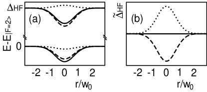
where is the spatially dependent hyperfine splitting in the presence of the light and measures the laser detuning from the center of the ground state hyperfine splitting. Equation 3 indicates that for , i.e. for and both positive (or both negative), the ground state energy splitting is always reduced by the presence of a light field (See Fig. 1). When the detuning is ”between” the hyperfine levels, , the energy splitting is enlarged.
For a FORT with detuning Eqs. 2,3 yield:
| (4) |
where is the spatially dependent dipole potential that forms the trap, in frequency units. The fact that the relative ac Stark shift is smaller than the dipole potential, is the main motivation for using FORTs for precision spectroscopy. For example in Ref. Davidson95 the relative ac Stark shifts were only times the dipole potential. Note that, however small, this relative ac Stark shift is still much larger than the spontaneous photon scattering rate Davidson95 .
For a trapped atomic ensemble, will cause a shift in the ensemble averaged ground state hyperfine energy splitting, . In addition, the spatial dependence of will result in an inhomogeneous broadening, , which depends also on the atoms’ temperatureNodynamics . For example, for a thermal ensemble of atoms with kinetic energy in an harmonic trap, we have and , where is the dipole potential at the trap’s bottom Kaplan02 .
In order to cancel these shifts, we introduce an additional laser beam, with intensity and frequency between the resonant frequencies of the two ground state hyperfine levels, say in the middle, i.e. and from the lower and higher hyperfine level respectivelyNomiddle . For a FORT, the total shift is obtained by adding the shifts from the trap and the compensating beam,
| (5) |
If the compensating beam is spatially mode-matched with the trap beam, i.e. , then a complete cancellation of the inhomogeneous broadening will occur for
| (6) |
Fig. 1 shows the shift of the hyperfine levels (a) and the hyperfine energy difference (b) caused by the trapping beam (dashed line) and compensating beam (dotted line). In the presence of both beams, the levels are shifted by the same amount (full line). As a specific example, with a FORT detuned by 5 nm we have . Hence, with a typical FORT power of 50 mW, the required compensating beam power is 20 nWnoted1 .
Note, that the dipole potential created by the compensating beam is for atoms in the upper an lower hyperfine level, respectively, and hence is negligible when compared with the potential of the FORT. Moreover, the photon scattering rate from the compensating beam is given by , which can be also written as . Hence, the scattering rate from the nearly resonant compensating beam, is of similar magnitude to that of the far-of-resonance trapping beam, .
We implement the proposed scheme with a FORT (a red-detuned gaussian beam Chu86 ), created by focusing a 50 mW laser, detuned 5 nm below resonance, to a waist of , resulting in a potential depth of ( is the recoil energy) and oscillation frequencies of Hz and Hz in the radial and axial directions, respectively. An additional laser, with frequency locked close to the middle of the ground state hyperfine splitting, is combined with the FORT laser. To achieve optimal spatial mode-match, both lasers are coupled into a polarization-conserving single-mode optical fiber, and the fiber’s output is passed through a polarizer and focused into the vacuum chamber. Two servo loops are used to control and stabilize the power of the lasers: The first one ensures a stability of the trap laser. More importantly, for complete compensation of the relative ac Sark shifts, a second servo loop ensures a stability of the power ratio throughout the entire duration of the experimentGratings .
The loading procedure is similar to that described in Ozeri99 . Briefly, the FORT is loaded by overlapping it with a compressed 85Rb magneto-optical trap (MOT). The MOT beams are shut off after 650 ms of loading, 50 ms of compression, and 5 ms of polarization gradient cooling, leaving confined atoms with a temperature of .

We perform a Rabi spectroscopy measurement on the trapped atoms by driving the ground state transition, which is insensitive to magnetic fields, to the first order. A bias magnetic field of 80mG is applied parallel to the FORT’s polarization axis and to the rf magnetic field direction, in order to Zeeman shift the magnetic sensitive levels out of resonance with the rf pulse. A typical sequence is as follows: First, the atoms are prepared in the ground state by turning on the MOT beams, without a repump beamOzeri99 , for 1 ms. Then, an rf pulse in applied at a variable frequency, using an Anritsu 69317B Signal Generator locked to a high stability oscillator. The intensity and duration of the pulse are adjusted to maximize the population when on-resonance ( pulse condition). Following the rf pulse, (the population in the level) is measured by detecting the fluorescence during a short pulse of a laser beam resonant with the cycling transition . The population of the level () is then measured by turning on the repumping beam (which is resonant with ) and applying an additional detection pulse. The normalized signal is insensitive to shot-to-shot fluctuations in atom number as well as slow drifting fluctuations of the detection laser frequency and intensityKhaykovich99 .
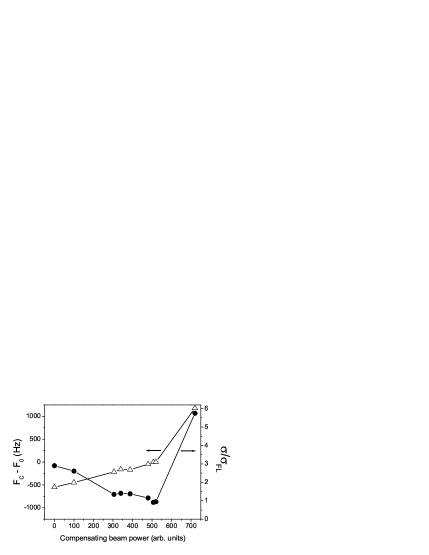
Figure 2 shows results for the Rabi spectrum with a 3 ms long pulse. A constant background resulting from spontaneous Raman scattering Cline94 is substracted. The spectrum of free-falling atoms shows no inhomogeneous broadening and a rms width, , which is Fourier limited to . A shift in the peak frequency (), and a broadening of the line (to ) are seen in the spectrum of trapped atoms, in fair agreement with the calculated trap depth and atomic temperature. This inhomogeneous broadening is not significantly affected by the duration of the pulse Nodynamics . The addition of the weak compensating beam, nearly cancels the broadening of the spectrum, as well as its shift from the free-atom line center.
Figure 3 shows the measured rms width and shift of the trapped atoms as a function of compensating beam power, again for a 3 ms rf pulse. The spectrum width is minimized to the Fourier broadening limit at a compensating beam power which corresponds also to a minimal shift from the free-atoms line center.

Figure 4 shows the measured rf spectrum for a 25 ms long pulse. A measurement of free atoms with this pulse length is not possible in our setup since the atoms fall due to gravity, and leave the interaction region. A Fourier limited is measured, representing a 25-fold reduction in the line broadening, as compared to the line broadening of trapped atoms. We performed a similar measurement with a 50 ms pulse, and observed a nearly Fourier limited width (a 50-fold narrowing), at the expense of a much larger spontaneous photon scattering and hence a smaller signalBackground5 . For even larger measurement times spontaneous photon scattering prevents further narrowing of the line.
We measure the spin relaxation rateCline94 ; Ozeri99 to be for atoms trapped in the FORT. The addition of the compensating beam induces an increase of only .
In summary, we perform an rf spectroscopy measurement of the hyperfine splitting of the ground state of optically trapped atoms. We demonstrate a novel scheme for eliminating the trap-induced inhomogeneous broadening of the transition, by adding a weak ”compensating” laser, spatially mode-matched with the trapping laser and with a proper detuning and intensity. Despite being tuned close to resonance, this laser induces a negligible change in the dipole potential, and does not considerably increase the spontaneous scattering rate. With the suppression of inhomogeneous broadening, the atomic coherence time is now limited by the much smaller spontaneous scattering time.
Whereas in a conventional optical trap the ac Stark shift of the line center strongly depends on the temperature of the atoms, which may drift considerably, in the compensated trap the suppression of the line shift is equally effective for all temperatures. Hence, it provides a mean of achieving a higher stability of the line center than that achieved by simply stabilizing the trapping laser detuning and intensity. For relative spectroscopic measurements, such as the proposed measurement of the electron’s permanent electric dipole moment (EDM)Chin01 , only stability (and not absolute accuracy) of the line center is of importance. For example, for a 10 K deep YAG-laser trap, and a compensating beam with a 15 KHz (time averaged) frequency stability, locking the relative intensity between both beams to a stability, will result in stability of the rf line center.
Finally, a weak compensating beam, spatially mode-matched with the trapping beam and properly tuned near resonance between the upper level of a laser cooling transition and another excited level, can suppress spatially dependent frequency shifts of the cooling transition, and allow simultaneous trapping and cooling with more flexibility than the single frequency method of Ref. Katori99 .
This work was supported in part by the Israel Science Foundation, the Minerva Foundation, and the United States-Israel Binational Science Foundation. MFA acknowledges help from the Nachemsohn Dansk-Israelsk Studienfond.
References
- (1) M. A. Kasevich, E. Riis, S. Chu, and R. G. DeVoe, Phys. Rev. Lett., 63, 612 (1989).
- (2) R. Grimm , M. Weidemuller, Y. B. Ovchinnikov, Adv. Atom. Mol. Opt. Phys. 42, 95-170 (2000).
- (3) S. Chu, J. E. Bjorkholm, A. Ashkin, and A. Cable, Phys. Rev. Lett. 57, 314 (1986).
- (4) J. D. Miller, R. A. Cline, and D. J. Heinzen, Phys. Rev. A 47, R4567 (1993).
- (5) N. Davidson, H. J. Lee, C. S. Adams, M. Kasevich, and S. Chu, Phys. Rev. Lett. 74, 1311 (1995).
- (6) C. S. Adams, H. J. Lee, N. Davidson, M. Kasevich, and S. Chu, Phys. Rev. Lett. 74, 3577 (1995).
- (7) T. Takekoshi and R. J. Knize, Opt. Lett. 21, 77 (1996).
- (8) N. Friedman, A. Kaplan, and N. Davidson, Adv. At. Mol. Opt. Phys., in press (2002).
- (9) J. P. Gordon and A. Ashkin, Phys. Rev. A 21, 1606 (1980).
- (10) S. J. M. Kuppens, K. L. Corwin, K. W. Miller, T. E. Chupp, and C. E. Wieman, Phys. Rev. A 62, 013406 (1999).
- (11) T. Ido, Y. Isoya, and H. Katori, Phys. Rev A 61, 061403 (2000); H. Katori, T. Ido and M. K. Gonokami, J. Phys. Soc. Jap. 68, 2479 (1999).
- (12) This is true when the position of each atom is fixed in time, and only an approximation for the more realistic case where the atoms move during the interrogation time.
- (13) A. Kaplan, N. Friedman, and N. Davidson, J. Opt. Soc. Am. B, In press (2002).
- (14) The detuning of the compensating laser can be chosen in the range , yielding a straightforward modification of Eqs. 5,6; however, choosing minimizes spontaneous photon scattering.
- (15) A similar calculation can be made which also takes into account also the contribution of the transition, and introduces only a small correction to Eq. 6.
- (16) Since typically in our experiment, the beams are separated by two gratings and two pinholes before their power can be measured independently.
- (17) R. Ozeri, L. Khaykovich, and N. Davidson, Phys. Rev. A 59, R1750 (1999).
- (18) L. Khaykovich, N. Friedman, and N. Davidson, Eur. Phys. J. D 7, 467 (1999).
- (19) R. A. Cline, J. D. Miller, M. R. Matthews and D. J. Heinzen, Opt. Lett. 19, 207 (1994).
- (20) All four states are populated and contribute to the spontaneous Raman scattering background, which is hence 5 times larger than that of an ideal 2-level system.
- (21) C. Chin, V. Leiber, V. Vuletic, A. J. Kerman, and S. Chu, Phys. Rev. A 63, 033401 (2001).