Optical feedback and the coupling problem in semiconductor microdisk lasers
Department of Physics, University of Oregon, 1371 E 13th Avenue, Eugene, OR 97403
Published in physica status solidi (a)188, 921 (2001))
Abstract
The smaller the size of a light-emitting microcavity, the more important it becomes to understand the effects of the cavity boundary on the optical mode profile. Conventional methods of laser physics, such as the paraxial approximation, become inapplicable in many of the more exotic cavity designs to be discussed here. Cavities in the shape of microdisks, pillars and rings can yield low lasing thresholds in a wide variety of gain media: quantum wells, wires and even dots, as well as quantum cascade superlattices and GaN. An overview of the experimental and theoretical status is provided, with special emphasis on the light extraction problem.
Light emission from microcavities is a problem of great fundamental and applied interest. A wide range of possible active media can be used to form microcavities, and consequently the properties of the microscopic dipoles which generate the light can vary significantly. One of our goals is to identify common, material-independent features of microcavity emitters, which are strongly determined by the geometric dimensions and shape of the cavity. Properties of interest are the spectrum of optical modes, their internal intensity distribution and the external field profile of the emitter. These characteristics in turn determine technological figures of merit, such as external quantum efficiency in the case of light emitting diodes (LEDs), or pump threshold and maximum output power in the case of lasers.
A problem in the design of LEDs is their poor external quantum efficiency, owing to the fact that light generated within the diode is not easily extracted. This is because total internal reflection at the interface between the semiconductor () and the surrounding lower-index medium () allows only those light rays to escape whose angle of incidence with respect to the surface normal satisfies
| (1) |
A first step toward better output coupling in LEDs is to reduce the vertical dimension (denoted by ) until a planar cavity is obtained [1]. The formation of Fabry-Perot modes in the direction leads to redistribution of spectral weight into peaks of the density of states [2, 3]. As a consequence, the spontaneous emission of the microscopic dipoles into the remaining cavity modes is enhanced according to Fermi’s golden rule [4, 5, 6].
This can lead to directional LED emission [7] because the resonant cavity modes are spatially anisotropic. In a microcavity laser, such as a VCSEL, the desired directional emission has to be balanced against the additional goal of obtaining laser oscillation at low threshold power. These two requirements are incompatible if we consider the conventional threshold condition that gain and loss must balance out: reducing the linear cavity dimension also reduces the available gain medium, and this eventually leads to an explosive increase in pump threshold if the mirror reflectivities are kept fixed [8]. On the other hand, increased mirror reflectivity means that the available output power is small.
Thus, it is desirable both for LED and laser applications to have as much freedom as possible in the “mirror design” of a microcavity, to create the analogue of the well-known stable, unstable or confocal configurations of macroscopic laser physics [9]. Clearly, vertical layer structures do not lend themselves to such a level of electromagnetic engineering. However, the lateral shape of a semiconductor microcavity can be chosen arbitrarily.
To calculate the cavity mode structure, recall that the laser oscillation condition implies that the wave equation has a solution with outgoing, but no incoming waves in the far field. This radiation boundary condition can be satisfied only at a discrete set of real numbers , where is the wavenumber and the exponential gain constant [10] of the active medium. This eigenvalue problem can equivalently be stated as a search for complex wavenumbers satisfying the above boundary condition with the index of the cavity at its transparency value; the solutions are known in scattering theory as the quasibound states [11]. This is what we mean by the term “modes” of the leaky cavity.
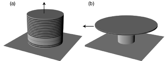
A possible lateral geometry for a VCSEL is that of a circular cylinder, cf. Fig. 1. It allows comparatively simple modeling because each of its layers can be considered as a short section of a cylindrical waveguide for which the modes are known analytically [12]. In particular, there are two types of modes in a cylinder, guided modes whose propagation constant in the z direction is large, and leaky modes with intensity localized close to the cylinder side wall. When piecing together the fields in the individual layers of the VCSEL stack [13], it is not surprising that we encouter both type of modes in pixelized VCSELs [14]. However, in a finite-sized, three-dimensionally confined dielectric cavity all modes are leaky, and in fact the large- modes can turn out to have lower Q than the ones with small , when leakage through the planar mirrors outweighs the lateral radiation losses. This was confirmed in the threshold behavior of a circular AlGaAs multiquantum well (MQW) cavity [14] of vertical thickness and radius m.
At large , the sidewalls allow waveguiding [15] and hence there is predominantly vertical emission, with the planar mirrors controlling the cavity Q factor. On the other hand, small leads to total internal reflection at the planar mirrors according to Eq. (1), because the angle of incidence satisfies , where is the free-space wavenumber, and the numerator describes the in-plane component of the internal wave vector. The lateral leakage is also controlled by total internal reflection, provided the light circulates close to the side wall close to grazing incidence; this is just the ray-optics equivalent of the ring-shaped intensity patterns which are commonly known as whispering-gallery (WG) modes, due to an acoustic analogue described first by Lord Rayleigh [4].
These ring-shaped modes thus avoid refractive escape according to Eq. (1) at all surfaces of the optical cavity. Hereafter, we define to be the angle of incidence with respect to the side wall normal to focus on the lateral emission properties. Neglecting absorption in the cavity, the WG mode Q-factor is limited only because internal reflection at the side walls is in fact frustrated by the finite surface curvature. This wavelength-dependent correction to the ray picture can be calculated straightforwardly within the WKB approximation [12, 16], and leads to infinite Q in the limit. The WKB method is here applied to the radial part of the wave equation governing the cavity field (after introducing cylinder coordinates); although it is a short-wavelength approximation, it has been found to provide quantitative results even in microcavities of dimensions comparable to the wavelength [11, 17, 18].
In contrast to a VCSEL mode, WG modes of a circular cavity emit predominantly sideways, and without any prefered azimuthal (in-plane) direction. For such edge emitting devices, Bragg mirrors on top and bottom of the cavity may be omitted [19], provided the index-difference between the guiding layer and surrounding cladding is large enough. The strongest index contrast clearly results if we manage to suspend the guiding layer in air. In this way, we get from the circular VCSEL to the microdisk laser [4]: like a thumbtack, the semiconductor disk is supported in the center by a pedestal which is thin enough to have only small or no interaction with the WG modes. Both optically and electrically pumped microdisks have been realized [20]. For better heat-sinking at room-temperature, one can also form the WG disk on pillars of other low-index material, e.g. AlxOy [21].
Rotational symmetry alone is not sufficient to permit exact analytic solution of the microdisk problem, however. The field of a given cavity mode depends on the cylindrical polar angle only through , where the integer is the analogue of a quantum mechanical angular momentum index. However, the radial () and dependence of the field remain coupled by the combination of boundary conditions at the vertical and lateral interfaces [22]. This makes it necessary either to perform numerical calculations in the plane [23], or to neglect this coupling by making a semivectorial approximation [20] which distinguishes between TE and TM modes. It is in fact confirmed numerically that the electric field of a given mode is either perpendicular to (TM) or in the disk plane (TE), up to small corrections.
If the disk thickness is small enough to satisfy , then only the fundamental slab-waveguide standing waves in the vertical direction are supported for both, TE and TM [22]. The corresponding range of thicknesses for semiconductor disks () is therefore approximately . The TE modes have higher Q than TM modes because the electric field is better confined in the vertical direction for TE; reported values for TE modes reach as high as in a m diameter disk with InAs self-assembled quantum dots (“boxes”) as emitters [25]. More typical Q factors are in the range from ; circular disks with such quality have been used to obtain lasing not only from conventional MQW structures [20] but also from InAs quantum wires in InP [26] where optical pump powers of mW were found at room temperature. In GaN, the introduction of a microdisk cavity led to a pump threshold reduction by an order of magnitude [27]. When only a single quantum dot acts as the emitter in the disk, lasing is not achieved but highly controlled emission of single photons under time-periodiv pumping has been demonstrated; the spontaneous-emission enhancement in the WG microcavity here serves to reduce the timing jitter [28].
The fact that a microdisk laser emits from its edge could be thought to cause extreme vertical spreading of the output radiation, if we recall that a slab waveguide of thickness has a divergence angle of order : with disks as thin as m emitting at m, the spreading should be prohibitive. However, this is not the case [23, 29]. The reason is that the far-field of a microdisk laser cannot be obtained from the near-field on its surface by a simple Fourier transformation, as would be the case for the planar output mirror of a VCSEL [30]. Rotational symmetry implies conservation of the -“angular momentum” between the interior and exterior fields, and this impresses a centrifugal potential onto the free-space propagation of the emitted light in the plane [11]. This in turn favors radial over vertical propagation, reducing the weight of large in the emission below that expected for a Gaussian beam. A rough estimate yields [23] a spreading angle (FWHM) .
The largest admitted by a microdisk cavity of radius and effective slab index can be estimated from the condition Eq. (1). One can show that semiclassically, a mode with azimuthal index corresponds to rays with angle of incidence satisfying , and since the maximum of is , we find that high-Q modes must have . As a consequence, becomes smaller for larger disk radii, provided they lase on WG modes close to grazing incidence at the side walls.
Whereas vertical focusing of the emission around the disk plane is thus surprisingly efficient, there is no easy prescription for inducing focused azimutal emission within this plane. As was recognized early on in the pioneering experiments of Slusher et al., the rotational symmetry of the disk has to be destroyed [31]. In the infinite space of possible shape deformations, it is challenging to find simple design rules that create preferential emission while at the same time preserving the desired high Q-factor. One type of shape perturbation that can never be ruled out is side wall roughness. It turns out, however, that both wavelength and Q factor of WG modes are quite insensitive to small random perturbations of the circular geometry [32]. Additional perturbative effects can be caused by the pedestal [33].
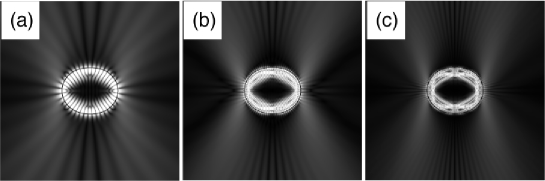
When the geometry of the disk is distorted to such an extent that perturbative treatments [34] break down, numerical modeling becomes much more complex because is no longer a “good quantum number” by which the modes can be labeled. Motivated by the success of the WKB method mentioned above, it was suggested early on that short-wavelength approximations can provide valuable insights into the mode structure and emission patterns of microlasers [11, 35, 36, 37]. The main observation is that the internal ray dynamics of a non-circular disk is in general chaotic, so that methods from the fields of classical and quantum chaos theory become applicable. Three chaotic WG modes are shown in Fig. 2, for a wide range of different wavelengths. At the deformation considered here, chaotic ray motion is the dominant mechanism for escape from the cavity, as opposed to diffractive (-dependent) effects. This is evidenced by the fact that in Fig. 2 depends only weakly on wavenumber . Likewise, one can identify wavelength-independent features in the internal and external intensity profiles; the emission directionality at large deformations is one of these characteristics, which to lowest order can be explained without recourse to the wave nature of light.
The first experimental tests of these predictions were performed on lasing dye microdroplets whose shape is generically oval [36]. When rotational symmetry is absent, in Eq. (1) is not conserved between reflections, so that diffusion of photons away from the WG region tends to occur; the modal decay rate then generally increases with deformation because even WG rays can reach Eq. (1) after sufficiently many loops in the cavity.
However, the Q-spoiling due to large deformation is less severe than expected from ray considerations alone, as was pointed out in Ref. [38]. An interference effect called “dynamical localization” actually suppresses decay rates in a manner analogous to Anderson localization in disordered solids [39], thus making high-Q asymmetric cavities more feasible: the advantages of asymmetric shapes for directional emission can then outweigh the loss in cavity Q.
Experimental realizations of non-circular microdisks [40] confirm another important prediction of the chaos analysis [35]: oval shapes favor WG lasing only as long as the boundary remains everywhere convex, i.e., has no points of vanishing curvature. The lateral emission from oval disks is found to emanate from the regions of highest curvature in semiconductor disks. The light furthermore escapes tangentially to the surface, as expected for rays at the critical angle of incidence just satisfying Eq. (1).
A striking exception to this rule is expected in similar structures made of polymers [41] or other low-index materials: the chaotic ray dynamics in such oval cavities [42] can counter-intuitively prevent WG rays from reaching at the high-curvature points. This “dynamical eclipsing” occurs because ray chaos is not random, but deterministic; its underlying structure can in particular rule out certain for WG trajectories approaching the high-curvature points. By changing the material (refractive index) of the cavity to bring into this “forbidden” range, the emission pattern for the same shape as in Fig. 2 then changes significantly.
In contrast to smooth oval deformations, one can also introduce notches or projections in the side walls, but this tends to increase vertical spreading [44], thus reducing the expected focusing of the laser. Recalling the dependence of vertical spreading on angular momentum, we should aim for smoothly deformed microdisks emitting near the critical angles of incidence, yet as anisotropic as possible. At large deformations, cavity modes with this property can have internal intensity distributions that are qualitatively different from WG modes.
This can be illustrated by a series of experiments on oval lasers, incrementally ramping up the deviation from circular shape. Such measurements have been performed in quantum-cascade microcylinders in the shape of a flattened quadrupole [43]. The devices were intended for high power and hence had larger area than the examples above: keeping the minor axis at m diameter and increasing the major axis to m, it was found that beyond a threshold deformation m, an exponential increase in the maximum achievable output power set in. The lasing mode was identified as belonging to a closed “bowtie” ray pattern which does not exist below the threshold deformation.
The effect of chaos in this experiment is to spoil all cavity modes overlapping the gain region, except for the bowtie modes. This reduces the density of available modes, while at the same time the internal intensity profile of the remaining modes becomes more focused in the electrically pumped center of the structure. The four vertices of the bowtie pattern meet the side walls near critical incidence, resulting in directional emission. The combined power of the four emission lobes of up to 10 mW was times larger than that of the circular device in the test series.
A special feature of the quantum-cascade system that makes it amenable to this near-critical mode is that (unlike the previous examples) it strongly favors emission in TM polarization. This is important because in a high-index cavity the critical angle for total internal reflection is close to the Brewster angle; therefore, near-critical TE modes suffer from much higher lateral emission than their TM counterparts (the reverse holds for the vertical losses).
A reduced permits reduced lasing thresholds, and the lesson learned from the bowtie laser is that chaos can reduce the mode density even in relatively large-area cavities. This is because the average of is not determined by the cavity volume, but by the available phase space volume for long-lived ray trajectories. The phase space occupied by a ray trajectory is determined by the real-space area it explores, combined with the range of it spans. We have recently shown [45, 46] that in a WG-cavity of mean radius (cf. Fig. 2) and index , the average number of long-lived (non-overlapping) modes per unit wavenumber interval is
| (2) |
The first term is determined by the cavity area, but the corrections for small show how the openness of the cavity reduces the density of modes by expanding the classical escape window Eq. (1) which depends on .
In conclusion, phase space reduction and hence lower threshold can be achieved by shrinking the real area of the cavity, e.g. with holes in the disk [44] or ring structures [47], or alternatively by engineering the side wall deformation to obtain stable modes such as the bowtie while simultaneously destablilizing most others. Concepts from nonlinear dynamics provide design guidelines for the latter approach. The rich structure provided by the ray dynamics in chaotic cavities makes it possible to design shapes for laterally directional emission, which makes it possible to collect the emitted light more efficiently than in rotationally symmetric structures.
References
- [1] H. De Neve et al., in J. Rarity and C. Weisbuch (eds.), Microcavities and Photonic Bandgaps, 333 (Kluwer Academic Publishers, 1996)
- [2] S. D. Brorson and P. M. W. Skovgaard, in Ref. [3]
- [3] R. K. Chang and A. J. Campillo (eds.), “ Optical Processes in Microcavities” (World Scientific, Singapore, 1996)
- [4] Y. Yamamoto, R. E. Slusher, Physics Today 46, 66 (1993)
- [5] G. Björk and Y. Yamamoto, IEEE J. Quant. Electron. 27, 2386 (1991)
- [6] F. Laeri and J. U. Nöckel, in Handbook of Advanced Electronic and Photonic Materials, Vol. 6, edited by H. S. Nalwa (Academic Press, San Diego, 2001)
- [7] H. Benisty, C. Weisbuch and V. M. Agranovich, Physica E 2, 909 (1998)
- [8] T. R. Chen et al., Appl. Phys. Lett. 60, 1782 (1992)
- [9] A. E. Siegman, Lasers (University Science Books, Mill Valley, 1986)
- [10] A. Yariv, Quantum Electronics (John Wiley, New York, 1975)
- [11] J. U. Nöckel and A. D. Stone, in Ref. [3].
- [12] A. W. Snyder and J. D. Love, Optical Waveguide Theory (Chapman and Hall, London 1991)
- [13] R. Kuszelewicz and G. Aubert, J. Opt. Soc. Am. A 14, 3262 (1997)
- [14] J. C. Ahn et al., Phys. Rev. Lett. 82, 536
- [15] L. Djaloshinski and M. Orenstein, IEEE J. Quant. Electron. 35, 737 (1999)
- [16] M. K. Chin, D. Y. Chu and S. T. Ho, Opt. Commun. 109, 467 (1994)
- [17] R. E. Slusher and U. Mohideen, in Ref. [3].
- [18] Jens U. Nöckel et al., Phys. Rev. E 62, 8677 (2000)
- [19] W. Zhou, P. Bhattacharya and O. Qasaimeh, IEEE J. Quant. Electron. 37, 48 (2001)
- [20] N. C. Frateschi and A. F. J. Levi, J. Appl. Phys. 80, 644 (1996)
- [21] D. S. Song et al., IEEE Photon. Technol. Lett. 12, 954 (2000)
- [22] R. P. Wang and M. M. Dumitrescu, J. Appl. Phys. 81, 3391 (1996)
- [23] B. J. Li and P. L. Liu, IEEE J. Quant. Electron. 33, 1489 (1997)
- [24] N. C. Frateschi and A. F. J. Levi, Appl. Phys. Lett. 66, 2932 (1994)
- [25] B. Gayral and J. M. Gérard, Physica E 7, 641 (2000)
- [26] C. Seassal et al., J. Appl. Phys. 88, 610 (2000)
- [27] S. S. Chang et al., Appl. Phys. Lett. 75, 166 (1999)
- [28] P. Michler et al., Science 290, 22 (2000)
- [29] T. D. Lee et al., Appl. Phys. Lett. 72, 2223 (1998)
- [30] M. Baier et al., Phys. Rev. Lett. 81, 2582 (1998)
- [31] A. F. J. Levi et al., Appl. Phys. Lett. 62, 561 (1992)
- [32] B. J. Li and P. L. Liu, IEEE J. Quant. Electron. 33, 791 (1997)
- [33] T. Baba, H.Yamada and A. Sakai, Appl. Phys. Lett. 77, 1584 (2000)
- [34] K. M. Lee, P. T. Leung, K. M. Pang, J. Opt. Soc. Am. A 15, 1383 (1998)
- [35] J. U. Nöckel, A. D. Stone and R. K. Chang, Opt. Lett. 19, 1693 (1994)
- [36] A. Mekis et al., Phys. Rev. Lett.75, 2682 (1995)
- [37] J. U. Nöckel, A. D. Stone, G. Chen, H. Grossman and R. K. Chang, Opt. Lett. 21, 1609 (1996)
- [38] J. U. Nöckel and A. D. Stone, Nature 385, 45 (1997)
- [39] O. A. Starykh et al., Phys. Rev. Lett.62, 2078 (2000)
- [40] S. A. Backes, A. P. Heberle, J. R. A. Cleaver and K. Köhler, phys. Stat. sol. (b) 204, 581 (1997)
- [41] A. Dodabalpur et al., Science 277, 1787 (1997)
- [42] S. S. Chang, J. U. Nöckel, R. K. Chang and A. D. Stone, J. Opt. Soc. Am. B 17, 1828 (2000)
- [43] C. Gmachl et al., Science 280, 1556 (1998)
- [44] S. A. Backes et al., J. Vac. Sci. Technol. B 16, 3817 (1998)
- [45] J. U. Nöckel and A. D. Stone, in preparation
- [46] I. Braun et al., Appl. Phys. B 70, 335 (2000)
- [47] D. Rafizadeh et al., Opt. Lett. 22, 1244 (1997)