WEDT003 INTRODUCING I/O CHANNELS INTO THE DEVICE DATABASE OPENS NEW POTENTIALITIES FOR CONFIGURATION MANAGEMENT ††thanks: Funded by the Bundesministerium für Bildung, Wissenschaft, Forschung und Technologie (BMBF) and the Land Berlin.
Abstract
The reference RDBMS for BESSY II has been set up with a device oriented data model. This has proven adequate for e.g. template based RTDB generation, modelling etc. But since assigned I/O channels have been stored outside the database (a) numerous specific conditions had to be maintained within the scripts generating configuration files and (b) several generic applications could not be set up automatically by scripts. In a larger re-design effort the I/O channels are introduced into the RDBMS. That modification allows to generate a larger set of RTDBs, map specific conditions into database relations and maintain application configurations by relatively simple extraction scripts.
1 Introduction
Within the last few years Relational DataBase Management Systems (RDBMS or DB in short) have become essential for control system configuration. With availability of generic applications and hardware standards the interplay of components as well as the adaptation to site specific needs has become crucial. Proper networking has been the central problem of the past. Today’s challenge is a central repository of reference and configuration data as well as an appropriate standard suite of DB applications. Target is a management system providing consistency in a programmable, comprehensible and automatic way for development, test and production phases of the control system. Instead of careful bookkeeping of innumerable hand-edited files the ever needed modifications of the facility require ‘only’ change of atomic and unique configuration data in the DB and eventually adaptation of structures in the DB (applications). The update of tool configurations is then consistently accomplished by direct DB connection, renewal of snapshot files generated by extraction scripts etc.
2 Status and Achievements
Very early a device oriented approach has been chosen for the description of the 3rd generation light source BESSY II. A naming convention was developed for easy identification and parsing of classifying properties like installation location, device family, type and instance. Around the ‘bootstrap’ information contained in the device names a first reference database has been set up [1], describing wiring, calibrations, geometries etc.
2.1 Device I/O
Utilisation of the EPICS control system toolkit implicates the network protocol called Channel Access for the I/O of process variables. At BESSY the device model results in a scheme <DEVICENAME>:<channel>.
Generation of the EPICS Real Time DataBases (RTDB) for device classes with high multiplicity and simple I/O (power supplies, vacuum system, timings) is based on two components: device class specific data are stored in the DB. Functionality and logic of <channel> is modelled with a graphical editor and stored in a template file. Generating scripts merge both into the actual RTDB.
For unique and complex systems (RF, insertion devices) structuring takes place in <channel> where no common naming convention has been defined so far. Contrary to the previous approach of complex template/atomic substitution here all channels involved are assigned to sub-units and hierarchies. The structure is fully implemented in the DB and for RTDB generation only connected with simple atomic templates.
Intermediate systems (scraper, GP-IB devices) are either adapted to one of these approaches or simply set up by ad-hoc created files.
2.2 Conditioning
Documentation of and transitions between different facility operation conditions are handled by a save/restore/compare tool that is working on a set of snapshot files. Coarse configuration is provided by SQL retrievals of name lists. Hierarchies and partitioning are derived from device-name patterns and mapped into directories and files. This is feasible only because the relevant channels are restricted to setpoint, readback and status. Deviations of this scheme are few and easily maintainable by hand.
Information required by modelling tools for conversion between engineering units of device I/O and the physics views (magnet function, length, position, conversion factor etc.) are fully available in the DB [2]. Therefore the linear optics correction tools (orbit, tune) are instantaneously consistently configured provided the installed hardware matches the entries in the DB.
2.3 Alarm, Archiving
As long as the alarm handler has to monitor only hardware trips DB retrieval of device name collections and script based interpretation of device name patterns are helpful at least for the simple devices with high multiplicity: typical channels are ON/OFF status. Again grouping and hierarchies can be derived from the class description embedded in the device name.
For the complex devices (RF) control functionality and logic has already been mapped into DB structures (see 1). Here genuine DB calls produce alarm handler configuration files with sophisticated error reporting capabilities.
In a similar fashion creation of configuration files for the data collector engine(s) of the archiving system is simplified by DB calls: for each device class a limited number of signals and associated frequencies are of interest for long term monitoring. The DB basically serves as source for device name collections.
2.4 Data Transfer
High level software using the CDEV API (configured with a device description language file) and ‘foreign’ networks (connected by the Channel Access gateway) benefit also from the DB: For CDEV access definition and permission to selected I/O channels for each device class is defined by appropriate prototype descriptions (in analogy to the RTDB templates). The associated lists of devices are compiled with DB calls. CA gateway takes advantage of the naming convention by regular expression evaluation.
2.5 Installation Procedures
Facility modifications typically change the device inventory. The DB supports consistent propagation of innovations [3]: During an installation campaign devices are added or deleted in the DB. In addition, new device classes are modelled within script logics and template (prototype) descriptions. Running the configuration scripts on all control system levels updates the configurations within development environment, test system and production area.
3 Solvable Deficiencies
A number of restrictions imposed by the present device oriented DB model are solvable by minor structural modifications and consequent introduction of channels necessary for the adequate description of essential device properties.
3.1 Device Ambiguities, Hierarchies
Dependent on the specific point of view, definition of device classes and assignment of equipment comprises ambiguities. E.g. the device class magnet (M) is tightly bound to the model aspect of the storage ring, whereas the the class power supply (P) covers the engineering aspects of the current converters. Pulsed elements (Kicker, Septa) are very similar devices, but do not fit into this scheme - neither into the model nor the I/O aspects. The decision to assign a single dedicated device-class (K) introduces a new pattern (fig. 2) and breaks the naming structure.
- HS4 3 D6 R
-
Magnet/Power Supply Numb. 3 in D6
Horizontal corrector (windings) in Sext 4 of… - (P)KI K 3 D1 R
-
Injection Kicker
if K then P power supply - UE56 I D6 R
-
Insertion Device presently installed in D6
ID UE56 as a complex device with lots of internal hardware units - (P)HB UE56 I 2 D6 R
-
Insertion Device Sub-Unit
if I then P power supply of
HB horizontal UE56bending magnet external access!
Difficulties get worse for complex pieces of equipment: insertion devices have to be treated as ‘units’. They can be completely replaced by different entities with similar complexity. Typically they consist of a number of devices partly belonging to already described device classes (like bipolar power supplies).
The straightforward solution here is the extension of the device naming convention: substructures and naming rules have to be introduced also for the (up to now monolithic) device property describing name element (‘genome chart’). Corresponding DB structures have to be implemented.
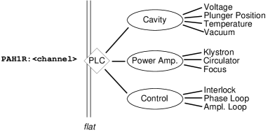
Similarly naming rules have to be developed where structuring takes place in <channel> (fig. 1). In summary, the distinction and boundary between device and <channel> are dictated by specifics of the I/O connectivity and arbitrary with respect to the required DB structure. It does not necessarily coincide with the most adequate classification aspects.
3.2 Context Dependent Role of Devices
Several global states are well defined for the whole facility (e.g. ‘shutdown’, ‘machine development’, ‘user service’ etc.) or for sub-sections or device collections: ‘injection running’, ‘wave length shifter ON’ etc. The role of devices depend on these states: in the context of ‘shutdown’ insufficient liquid helium level at super-conducting devices has to generate a high severity alarm. For power supplies even OFF states are then no failure. But during ‘user service’ alarms should notify the operator already when power supply readbacks are out of meaningful bounds.
Similar case distinctions have to be made for all conditioning applications (reload constraints for save/restore, active/inactive elements for modelling), for data archiving (active periods, frequency/monitor mode), for sequencing programs etc. Today only the most general conditions are statically configured and available from the database/configuration scripts. Exceptions are partly coded within the applications or have to be handled by the operators — an error-prone situation.
A clearly laid out man-machine interface provides an effective protection against accidental maloperation. Presentation details and accessibility of devices should be tailored to the user groups addressed: Operators, device experts, accelerator physicists. The required attributes attached to the device channels should be easily retrievable from the DB.
4 Structural Shortcomings
4.1 Immature Data Model
Starting from the device model a very specific view of the control system structure has been mapped into DB structure: device classes correspond to tailored set of tables. Deviating aspects that do not fit into the scheme are modelled by relations, constraints, triggers and presented to the applications by pre-built views. The result is not very flexible, hard to extend and complicated to maintain in a consistent state free from redundancies. Numerous device attributes are scattered over template/prototype files and configuration creating scripts in an implicit format without clear and explicit relation to the data within the DB.
4.2 Unavailable Data
Configurations of archiver retrieval tools are much more demanding than those of data collector processes. In search of correlations arbitrary channel names have to be detected by their physical dimension: for a drift analysis the data sources for temperatures [C], RF frequency [MHz], BPM deviations [mm] and corrector kicks [mrad] have to be discovered. Any non-static, not pre-configured retrieval interface to the most important performance analysis tool of the facility –archived data– requires clues to signal names, meaning, functionality, dimensions, attributes.
With the RTDB template approach the channel attributes are hidden within these files and not available to the DB. Consequently, no DB based data relations are available for correlations (comparable dimensions), projections (user, expert, device responsible) or dependencies (triggered by). There is no browsable common data source that allows to coordinate consistency of configurations requiring channel attributes (that go beyond simple and clear assignments to well defined device classes). The device model is tailored for modelling applications. For the archiver retrieval it is useless continuously causing errors and inconsistencies.
5 Solution Attempt
In a kind of clean-up effort the existing fragments used for RTDB generation will be put into a new scheme. Sacrificing the feasibility to generate complex RTDB templates with a graphical editor, now device class tables, templates and I/O software modules (records) will be put together as a new DB core. In view of the extendibility for high level applications a purely DB based approach has been taken — even though for RTDB generation the framework of XML seems to be an attractive and well suited alternative.
A new entity gadget is introduced connecting the data spaces Device, Channel and IOstruct. These DB sections have to be set up consequently in 3rd normal form, i.e. all device class properties, channel attributes and I/O specifics have to be modelled in data and relations, not in table structures. In blue-print the resulting data model looks abstract and (intimidating) complex, but promising with respect to DB flexibility, extendibility and cleanness. Expectation that today’s complicated configuration scripts collapse to simple sequences of DB queries seem to be justified.
6 SUMMARY
The most difficult problem of a comprehensive configuration management system is the determination of ‘natural’ data structures and breaking them down into localised data areas, dependencies and relations. For a relatively small installation like BESSY II the expected reward in stability and configuration consistency does not clearly justify effort and risk of the envisaged re-engineering task. One could argue that the present mixture of DB based and hand edited configuration is an efficient compromise. On the other hand the persistent and boring work-load due to manual configuration update requirements is a constant source of motivation to persue this reengineering project.
References
- [1] R. Bakker, T. Birke, B. Kuske, B. Martin, R. Müller, Proc. of the 6th Int. Conference on Accelerator and Large Experimental Physics Control Systems (ICALEPCS97), Beijing, 1997.
- [2] R. Bakker, T. Birke, B. Kuske, R. Müller, Proc. of the Automated Beam Steering and Shaping Workshop, CERN, CERN 99-07, p. 97, 1998.
- [3] R. Müller, R.J. Bakker, T. Birke, R. Lange, Proc. of the 7th Int. Conf on Accelerator and Large Experimental Physics Control Systems (ICALEPCS99), Trieste, p. 326, 1999.