A Single Shot, Sub-picosecond Beam Bunch Characterization with Electro-optic Techniques
Abstract
In the past decade, the bunch lengths of electrons in accelerators have decreased dramatically to the range of a few picoseconds Uesaka94 ; Trotz97 . Measurement of the length as well as the longitudinal profile of these short bunches have been a topic of research in a number of institutions Uesaka97 ; Liu97 ; Hutchins00 . One of the techniques uses the electric field induced by the passage of electrons in the vicinity of a birefringent crystal to change its optical characteristics. Well-established electro-optic techniques can then be used to measure the temporal characteristics of the electron bunch. In this paper we present a novel, non-invasive, single-shot approach to improve the resolution to tens of femtoseconds so that sub-millimeter bunch length can be measured.
I Introduction
The development of very short beam pulses is a crucial part of the effort to achieve the desired luminosity for the future accelerators which are being designed to bring us to the next energy frontier and for SASE for FEL. The Lorentz cone of an ultra-relativistic charged particle beam bunch (CPB) has a very small opening angle jackson and therefore the amplitude of the generated electric field has a longitudinal profile very close to the longitudinal charge distribution of the beam. One way to measure the produced electric field in a non-invasive way is the electro-optic effect (Pockels effect) using an electro-optic crystal as the electric field sensor. A polarized laser light goes through the electro-optic crystal and the E-field from the CPB induces an ellipticity in the polarization state of the laser light. Ellipsometer techniques are used to analyze the laser light polarization state. The first electro-optic detection of charged particle beams have been reported in references pac99 ; yan00 ; fitch01 ; semertzidis00 ; tsang01 .
The techniques that are used to read out the ellipsometers are:
-
1.
The pump-probe method where a short laser pulse is used with a determined time delay between the electron beam and the laser pulse. The time delay is varied so different parts of the electron beam can be probed. This approach can in principle give the average longitudinal beam profile of many electron pulses yan00 ; fitch01 .
The time resolution of this method is determined by the appropriate combination of the laser pulse length, the laser pulse size in the crystal and the crystal length () along the laser propagation direction. The latter is equal to with the speed of light and the index of refraction for the crystal at the laser frequency. For a crystal length of 1 mm, ps. If the CPB length is shorter than the crystal length, the time resolution would be equal to the CPB pulse length. If the laser pulse and the CPB move in the same direction then the pulse broadening equals ps for the above example which is consistent with the resolution reported in reference yan00 . In order to reach sub-picosecond time resolution the crystal length needs to be less than . Crystals with or smaller lengths are already commercially available.
-
2.
The single shot technique where the light after the ellipsometer is either (a) read by a streak camera dimitri01 , or (b) the laser light is stretched after it goes through the crystal so that the signal can become slow enough to be read out using conventional electronics Hutchins00 or (c) by measuring the laser pulse spectra with and without the presence of an electron pulse wilke01 . The advantage of the single shot method is that it can, in principle, provide information on the longitudinal beam profile on a single pulse basis.
The time resolution of this approach is limited by the laser pulse size in the crystal and the crystal length along the laser propagation.
We report a recent development triveni01 based on the electro-optic effect which is capable of reaching sub-picosecond time resolution down, in principle, to a few fs in the single shot mode.
II Theory
Let us consider an electron beam bunch of charge density , and bunch length , focused to a sheet beam with transverse dimension . Let this relativistic charged particle beam move along axis, the length of a birefringent crystal. The electric field experienced by the crystal at a distance r from the electron beam, due to the charge can be written as
| (1) |
where is the dielectric constant of the crystal in Z direction and is the relativistic Lorentz factor. This field is present at this location for the time taken by this charge to traverse the distance . A polarized laser beam propagating along the y-axis inside this birefringent crystal would then experience this field over a distance where n is the refractive index of the crystal, along the direction of propagation at the laser frequency. The phase retardation experienced between the two orthogonal polarization components (z and x) of the laser beam is:
| (2) |
where is the electro-optic coefficient and is the wavelength of the laser beam. The total retardation is obtained by integrating over the entire charge distribution, the time taken by the laser to cross the crystal and the length of the crystal. The limits of integration would then depend on the smaller of these interrelated parameters. If the transmitted laser beam is detected after passing through a quarter wave plate and a crossed analyzer, then the transmitted intensity I(t) is given by
| (3) |
where is the intensity extinction coefficient, is the residual retardation by the crystal in the absence of the electric field and is the retardation introduced by the quarter wave plate. Typical values for and are in the range of tens of milliradians. The value of is chosen to suit the detector capabilities and the experimental conditions.
III Measurement of sub picosecond electron bunch length
This scheme has been successfully used to measure the bunch length of 45 MeV electron beam semertzidis00 ; tsang01 . The limit on the resolution had been the bandwidth of the detection system. A number of schemes to measure sub-picosecond electron bunch have been proposed so far. These include characterizing the frequency modulation on a laser spectrum caused by the electron bunch, performing autocorrelation measurements and using the FROG technique to determine both the frequency and time distribution of the laser beam transmitted through a birefringent crystal. In the following section another scheme that converts temporal information to spatial information to measure sub-picosecond electron bunch is described. Bunch length measurement with resolution down to the response time of the crystal is possible using this method since linear arrays with small pixel dimensions is readily available. Furthermore, where pixel dimension proves to be the limitation, effective use of optical imaging can be used effectively to overcome this limitation.
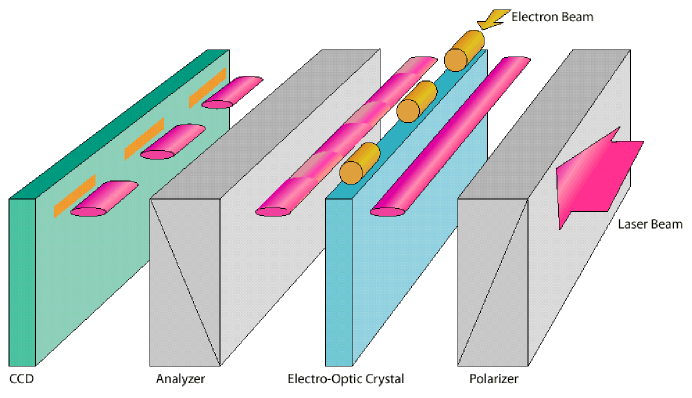
A short laser pulse polarized in the YZ plane, 45o to the z-axis, focused using a cylindrical lens to form a line focus, propagates along the y-axis. A thin birefringent crystal with optic axis along z and ordinary axis along x is positioned at the waist of the laser beam. The electron bunch propagates simultaneously along the x-axis, at a minimum distance r from the laser beam. The transmitted intensity is passed through a crossed analyzer and detected by a linear detector array. As shown in the Figure 1, only those sections of the laser beam that are below the electron bunch will experience a phase retardation linearly proportional to the charge density of the electron beam and reach the linear array. The acceptable jitter between the electron beam bunch and the laser beam is determined by the x dimension of the crystal, length and sensitivity of the detector array, length of the line focus of the laser and laser energy available. For a typical diode array of 1024 elements, 1 cm crystal length and 100 pJ of laser energy in a 1 cm line focus, jitter up to 30 ps can be tolerated as well as measured using this arrangement.
The pulse duration and the thickness (y dimension) of the crystal determine the resolution and fidelity of the temporal profile. The distance traveled by the electron bunch during the laser pulse constitutes the uncertainty in the bunch length measurement. A relativistic electron travels during a laser pulse duration of 50 fs (for ), causing a corresponding broadening of the image on the detector array. The laser pulse duration should then be a small fraction of the electron pulse duration to be measured. Short laser pulses down to tens of femtoseconds are readily achievable. However, the optical beam transport must be designed carefully to reduce pulse broadening and minimize high order dispersion.
The phase rotation of a single photon traveling along the crystal is caused by the integrated charge density along the diagonal of the sheet of charge, seen by the photon while in the crystal. Thus, only an infinitely thin crystal would preserve the temporal profile of the electron bunch. The choice of the thickness of the crystal is, hence, a function of the magnitude of the obtainable electric field (determined by charge density achievable and distance between the electron beam and the laser), the electro-optic coefficients, the sensitivity of the detection system, and the structural integrity of the system.
In conclusion a number of electro-optic detection schemes are available to measure the length of subpicosecond electron bunches. These techniques need to be tested for limitations before a judicial choice can be made.
References
- (1) M. Uesaka et al., Phys. Rev. E, Vol. 50, No. 4 (1994), p 3068.
- (2) S. Trotz, W. J. Brown, B. G. Danly, J.-P. Hogge, M. Khusid, k. E. Kreischer, M. Shapiro and R. J. Temkin, Proc. Advanced Accelerator Concepts, Ed. S. Chattopadhyay, J. McCullough and P. Dahl, AIP Press, NY, (1997) P. 717.
- (3) M. Uesaka, T. Ueda, T. Watanabe, M. Kando, K. Nakajima, H. Kotaki, and A. Ogata, Proc. Advanced Accelerator Concepts, Ed. S. Chattopadhyay, J. McCullough and P. Dahl, AIP Press, NY, (1997), p 687.
- (4) Y. Liu, d. B. Kline, X. J. Wang, M. Babzien, J. M. Fang and V. Yakimenko, Proc. Advanced Accelerator Concepts, Ed. S. Chattopadhyay, J. McCullough and P. Dahl, AIP Press, NY, (1997), p 664.
- (5) S. C. Hutchins, CLF Tech Note 2000-06, CERN, Geneva
- (6) J.D. Jackson, Classical Electrodynamics, 2nd Ed., John Wiley & Son, NY, 1975, p. 555.
- (7) Y.K. Semertzidis et al., Proc. PAC’99, p.490.
- (8) X. Yan et al., Phys. Rev. Lett. 85, 3404 (2000).
- (9) M.J. Fitch et al., Phys. Rev. Lett. 87:034801, 2001.
- (10) Y. K. Semertzidis, V. Castillo, L. Kowalski, D. E. Kraus, R. Larsen, D. M. Lazarus, B. Magurno, D. Nikas, C. Ozben, T. Srinivasan-Rao, and T. Tsang, NIM A452/3, (2000), p 396.
- (11) T. Tsang, V. Castillo, R. Larsen, D. M. Lazarus, D. Nikas, C. Ozben, Y. K. Semertzidis, T.Srinivasan-Rao, and L. Kowalski, Journal of Applied Physics, Vol. 89, No. 9, (2001) p. 4921.
- (12) D. Nikas et al., in preparation.
- (13) I. Wilke et al., Abstract contribution # Tu-O-10 to FEL2001, 20-24 August, 2001, Darmstadt, Germany.
- (14) T. Srinivasan-Rao et al., presentation at the 21st ICFA Beam Dynamics Workshop on Laser-Beam Interactions, 11-15 June, 2001, Stony Brook, USA.