[
Deviation from Snell’s Law for Beams Transmitted Near the Critical Angle: Application to Microcavity Lasers
Abstract
We show that when a narrow beam is incident upon a dielectric interface near the critical angle for total internal reflection it will be transmitted into the far-field with an angular deflection from the direction predicted by Snell’s Law, due to a phenomenon we call “Fresnel Filtering”. This effect can be quite large for the parameter range relevant to dielectric microcavity lasers.
pacs:
OCIS codes: 140.3410,140.4780,230.3990,230.5750,260.2110,260.5740]
A promising approach to making high-Q optical micro-cavities and micro-lasers is to base them on totally-internally reflected modes of dielectric microstructures. This approach is currently under intense investigation with resonators and lasers based on a range of shapes: disks, cylinders, spheres [1], deformed cylinders and spheres [2, 3, 4, 5, 6, 7] squares [8] and hexagons [9]. Many different mode geometries have been observed in such resonators, e.g. whispering gallery modes [1], bow-tie modes [2, 3], triangle [6, 7] and square modes [8]. Typically these modes correspond to ray trajectories which are incident on the boundary of the resonator above or at the critical angle in order to achieve adequately high Q-values and may correspond to periodic ray “orbits” (POs) which are either stable, unstable or marginally stable. The natural and simplest method for predicting how such a mode will emit or scatter light is simply to apply Snell’s law to the underlying ray orbit and follow the refracted ray into the far-field. For a ray which is incident at the critical angle this would imply emission in the direction tangent to the emission point. However in several recent experiments very large deviations from this simple expectation were observed [2, 7]. We show below that such observations may be explained as arising from the angular spread in the resonant mode around the PO, and the very rapidly varying transmission probability as a function of angle near the critical angle. This “filters” out the angular components which are totally internally reflected (TIR) and preferentially transmits those which are far from TIR, leading to a net angular rotation of the outgoing radiation from the tangent direction. We call this effect Fresnel Filtering (FF).
The basic effect occurs for a bounded beam of arbitrary cross-section incident from a semi-infinite medium of index into vacuum, although it will be quantitatively altered in a resonator due to the curvature and/or finite length of the boundary. We thus begin with the infinite planar example, which we can solve analytically, before presenting numerical results for quadrupolar asymmetric resonant cavities (ARCs)[10]. There is a large literature on reflection of a beam from a dielectric interface near or above the critical angle, as the reflected beam exhibits the Goos-Hänchen lateral shift as well as other “non-specular” phenomena [11]. However only a few of these works address the transmission [12, 13] of the beam and these tend to focus on the evanescent effects in the near field; none appear to have identified the Fresnel Filtering effect and its relevance to dielectric micro-cavity resonators.
For simplicity, we consider a two-dimensional planar interface which separates two semi-infinite regions with a relative dielectric constant . Consider a beam incident from the denser region with a central incidence angle . We will take the beam to be gaussian with a minimum beam waist (which we will use to scale all lengths henceforth) at a distance from the interface. The basic effect is independent of the nature of the input beam as long as it is focused and has significant angular spread. The corresponding Snell emission angle (which is in general complex) is given by . and refer to coordinates tied to the incident and refracted beams respectively (see Fig. 1 inset). We will consider linearly polarized beams, the corresponding beam fields will then denote the electric () or the magnetic () fields normal to the plane of incidence.
Using the angular spectrum representation [14], the incident beam in coordinates will consist of a superposition of plane waves of the same frequency with a gaussian distribution of transverse wavevectors , where , is the wavevector in vacuum and is the deviation angle of the plane wave component from :
| (1) |
where and the dimensionless width parameter .
The beam on the side of the interface in polar coordinates (, ) attached to the interface (after refraction) is then given by the integral:
| (3) | |||||
Here is obtained from and is given by:
| (4) |
Evaluating this integral in the asymptotic farfield () using the saddle point method we obtain our “gaussian model” (GM) for FF field:
| (5) |
where the transmission functions, evaluated at the relevant saddle point
| (6) |
are given by
| (7) |
Here, for and for . The relevant saddle point arises from setting to zero the derivative of the cosine in the exponent of Eq. (3); this saddle point value selects the angular component which refracts into the observation direction by Snell’s law. However the amplitude factor obtained by gaussian integration around the saddle point shifts the maximum of the outgoing beam away from the Snell direction. As noted, the effect occurs for narrow beams with an arbitrary (non-gaussian) wavevector distribution ; in such a case the factor in Eq. (5) is replaced by (see e.g. ref. [7]).
Eq. (5) gives the angular beam profile in the far-field, which is non-zero for any incident angle , even . The key point is that the angular maximum of this outgoing beam, , is in general not at the angle predicted by applying Snell’s law to the central incident beam direction . Instead, due to the unequal transmission of the different angular components, the beam direction is shifted by an angle corresponding to less refraction than expected from Snell’s law. This angular deflection can be quite large for incidence near in typical microcavity resonators; in Fig. 1 the dashed line is the result of Eq. (5) for critical incidence, for which the Snell angle is , but giving . The farfield peak-shift depends on the beam width and on ; analysis of the stationary phase solution gives the result that at
| (8) |
which predicts for the parameters of Fig. 1.
Two technical points are in order here: First, while deforming the contour of integration in Eq. (3) to the steepest descent path, depending on how , and are situated, one might intercept branch cuts due to the branchpoints and . Such branchpoint contributions are well-studied for the reflected beam shifts[15, 16], but the contribution is subdominant with respect to the first order asymptotic term derived in Eq. (5); we neglect such terms here. Second, there is another saddle point which corresponds to angular components with grazing incidence to the interface. Because the Fresnel transmission factor vanishes for such components only contributes to the integral at order . This contribution only becomes important very near , where the dominant contribution from also vanishes, and again we neglect such terms in the current work.
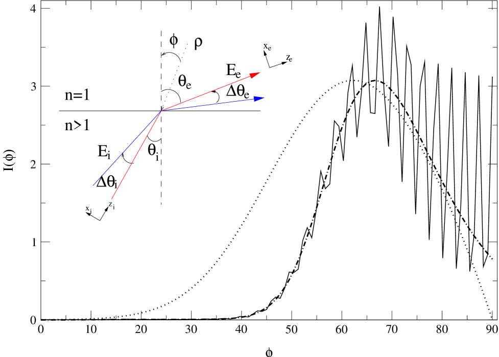
Clearly the same Fresnel Filtering effect will occur in emission from dielectric resonators with a magnitude similar to the planar case when the typical radius of curvature is much larger than . As an example, we investigate the effect of FF on the farfield emission pattern of quadrupolar ARCs [10, 6, 2, 7], dielectric cylinders with cross-section given by . We study the exact numerically generated quasibound TM modes of a resonator with () deformation for different values of the refractive index , focusing on resonances based on the stable four-bounce (“diamond”) PO. The numerical method used is a variant of the “S-matrix method” for billiards [17, 18]. If, as in this case, the relevant orbit is stable and we neglect leakage, then it is possible to construct [19] approximate modes which are piecewise gaussian on each segment of the PO. From this theory one finds that the effective beam waist in each segment will scale as , where is a constant dependent only on the stability matrix eigenvectors of that particular segment, and is the quantized eigenvalue of the mode. In Fig. 2 (a) we plot one representative quasi-bound mode at ; the corresponding far-field angular intensity is plotted in Fig. 1.
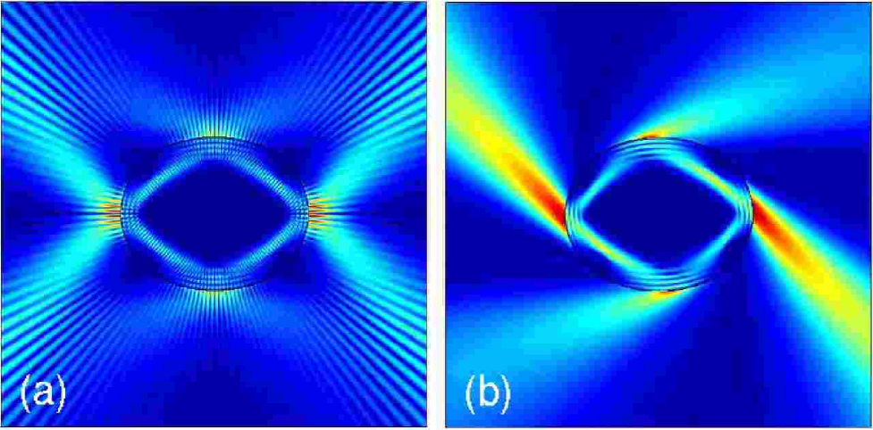
In both figures one sees the rapid oscillations due to interference, but in Fig. 1 one can see that the maximum of the intensity is displaced from as expected due to Fresnel Filtering. To compare the size of the effect to our analytic theory for a planar interface it is convenient to eliminate the interference by calculating the “chiral” resonance shown in Fig. 2 (b). This is the original resonance with the negative angular momentum components projected out, hence mimicking a uni-directional beam. When this is plotted in Fig. 1 (dot-dashed line) it gives the smooth envelope of the diamond resonance without the oscillations. We can regard this chiral resonance as a beam incident at on the boundary and compare it to our planar model. The angle of incidence of the “beam” with respect to the tangent plane is , and we have chosen so that ; hence naive ray optics predicts tangent emission (). From Fig. 1 one sees that the resonance emission is peaked at , whereas the planar model gives a similar envelope slightly shifted with . In evaluating the planar model we use and as calculated from the gaussian theory of this diamond resonance, hence we have no free parameters. The observed difference is likely due primarily to the effect of the curvature of the boundary.
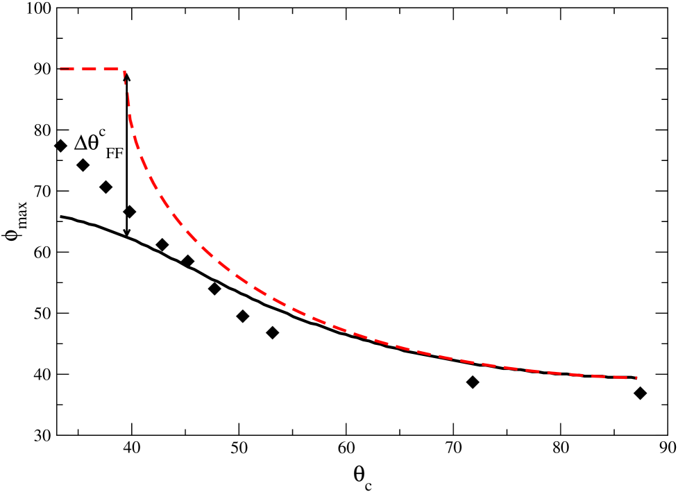
To evaluate systematically the Fresnel Filtering effect, we have calculated the farfield peaks of the set of diamond resonances while varying the index of refraction, so that the critical angle is scanned through the PO incidence angle . In order to remain as close as possible to our GM with fixed we have chosen the resonances so that is approximately constant. In Fig. 3, the exact numerical resonance peak is compared to the calculated from Eq. (5) and to the direction predicted by Snell’s law. Clearly the deviation from Snell’s law, , varies with distance from ; further studies find that this region of significant deviation decreases with increasing as expected.
In conclusion, we have shown that the transmission direction of a narrow beam through a plane dielectric interface can be quite different from the direction predicted by applying Snell’s law to the incident beam direction. This effect is due to a phenomenon we call Fresnel Filtering and is of great importance in predicting the emission patterns from resonances based on periodic ray orbits in micro-cavity lasers. This is true even when the size of the resonator is much larger than the wavelength and one might have expected ray optics to be quite good. Specifically the effective beam waist for stable resonances scales as , so from Eq. (8) the deviation angle at critical incidence , and hence may be large for as in recent experiments on semiconductor ARC lasers [2, 3, 7].
We acknowledge helpful discussions with H. Schwefel, N. Rex and R. K. Chang. This work was supported by NSF grant DMR-0084501.
REFERENCES
- [1] For examples and references, see R. K. Chang and A. J. Campillo, Eds., Optical Processes in Micro-cavities (World Scientific, Singapore, 1996).
- [2] C. Gmachl, F. Capasso, E. E. Narimanov, J. U. Nöckel, A. D. Stone, J. Faist, D. L. Sivco, and A. Y. Cho, Science 280, 1493 (1998).
- [3] S. Gianordoli, L. Hvozdara, G. Strasser, W. Schrenk, J. Faist, E. Gornik, IEEE J. Quantum Elect. 36, 458 (2000).
- [4] S.-C. Chang, R. K. Chang, A. D. Stone and J. U. Nöckel, J. Opt. Soc. Am. B 17, 1828 (2000).
- [5] N. B. Rex, R. K. Chang and L. J. Guido; abstract, CLEO/QELS 2000, 2001; Proc. SPIE 3930, 163 (2000).
- [6] A. D. Stone, Physica Scripta T90, 248 (2001).
- [7] N. B. Rex, H. E. Tureci, H. G. L. Schwefel, R. K. Chang and A. D. Stone, http://xxx.lanl.gov/abs/ physics/0105089.
- [8] A. W. Poon, F. Courvoisier and R. K. Chang, Opt. Lett 26, 632 (2001).
- [9] I. Braun, G. Ihlein, F. Laeri, J. U. Nockel, G. Schulz-Ekloff, F. Schuth, U. Vietze, O. Weiss and D. Wohrle, Appl. Phys. B 70, 335 (2000).
- [10] J. U. Nöckel and A. D. Stone, Nature 385 45 (1997).
- [11] T. Tamir, J. Opt. Soc. Am. A3, 558 (1986).
- [12] J. W. Ra, H. L. Bertoni, and L. B. Felsen, SIAM J. Appl. Math. 24, 396 (1973).
- [13] Y. M. M. Antar, Can J. Phys. 55, 2023 (1977).
- [14] L. Mandel and E. Wolf, Optical Coherence and Quantum Optics (Cambridge University Press, New York, 1995).
- [15] L. B. Felsen and N. Marcuvitz, Radiation and Scattering of Waves (IEEE Press, New York, 1994).
- [16] L. M. Brekhovskikh, Waves in Layered Media (Academic Press, New York, 1980).
- [17] B. Dietz and U. Smilansky, Chaos 3, 581 (1993).
- [18] S. D. Frischat and E. Doron, J. Phys. A bf 30, 3613 (1997).
- [19] V. M. Babič and V. S. Buldyrev Asymptotic Methods in Shortwave Diffraction Problems (Springer-Verlag, Berlin, 1991).