SLAC–PUB–8884
June 2001
Frequency Resolved Measurement of Longitudinal Impedances Using Transient Beam Diagnostics111Work supported by Department of Energy contract DE–AC03–76SF00515.
D. Teytelman, J. Fox, S. Prabhakar
Stanford Linear Accelerator Center, Stanford University, Stanford, CA 94309
J. Byrd
Lawrence Berkeley National Laboratory, 1 Cyclotron Road, Berkeley, CA 94563
Abstract
In this paper we present several techniques for characterizing longitudinal impedances based on transient measurements of the growth rates and tune shifts of unstable coupled-bunch modes. These techniques are applicable to measurement of both fundamental and higher-order mode impedances and allow characterization of shunt impedances and quality factors of the HOMs. Methods presented here are complementary to lab bench measurements of RF cavities, in that the beam based measurements directly sense the physical impedance in the installed configuration. In contrast to a single-bunch integrated impedance measurement these techniques resolve the impedances in the frequency domain. These methods allow determination of the impedance’s unaliased frequency by analyzing synchronous phase transients. Experimental results from ALS and BESSY-II are presented showing the use of these techniques to measure complex impedances.
Presented at IEEE Particle Accelerator Conference (PAC 2001), Chicago, Illinois, 18-22 Jun 2001
Frequency Resolved Measurement of Longitudinal Impedances Using Transient Beam Diagnostics††thanks: This work was supported by DOE contract No. DE-AC03-76SF00515
Abstract
In this paper we present several techniques for characterizing longitudinal impedances based on transient measurements of the growth rates and tune shifts of unstable coupled-bunch modes. These techniques are applicable to measurement of both fundamental and higher-order mode impedances and allow characterization of shunt impedances and quality factors of the HOMs. Methods presented here are complementary to lab bench measurements of RF cavities, in that the beam based measurements directly sense the physical impedance in the installed configuration. In contrast to a single-bunch integrated impedance measurement these techniques resolve the impedances in the frequency domain. These methods allow determination of the impedance’s unaliased frequency by analyzing synchronous phase transients. Experimental results from ALS and BESSY-II are presented showing the use of these techniques to measure complex impedances.
1 Introduction
The interaction of charged particles in a storage ring or circular accelerator with the ring impedance determines many important accelerator dynamics parameters. Single and multi-bunch instabilities are the result of interactions of the bunches with the impedance of the machine, and achieving high stored currents requires knowledge and control of the ring components which produce the dominant narrow-band impedances. There are several laboratory techniques to measure impedances of physical components [1, 2]. Beam-based impedance measurement techniques exist as well. Frequency-resolved information about the coupling impedance can be extracted from a measurement of the beam transfer function (BTF) [3]. However such a measurement can only be performed below the instability threshold. In addition network analyzer sweeps have to be repeated for each unstable mode making BTF approach slow and cumbersome.
This paper presents several beam-based longitudinal impedance measurement techniques. These fast transient multi-bunch techniques measure the aliased longitudinal impedance as a function of frequency in a sampling bandwidth up to 1/2 the RF frequency. Consequently various higher-order mode resonators can be identified and their complex impedance (and parameters such as center frequency and Q) measured.
2 Longitudinal impedances and coupled-bunch instabilities
Bunches of charged particles passing through the vacuum chamber of a storage ring leave behind electromagnetic fields. These fields (wake fields) affect the energy of the following bunches providing a bunch-to-bunch coupling mechanism. At high beam currents such coupling can cause instabilities.
The bunch motion in a storage ring can be projected onto the orthonormal basis of the even fill eigenmodes (EFEMs). Eigenvalue of mode is given by [4]
| (1) | |||
| (2) |
where is the radiation damping rate, is the synchrotron frequency, is the momentum compaction factor, is the charge of the electron, is the frequency in the accelerating cavities, is the beam current, is the beam energy, is the ring harmonic number, is the revolution frequency, and is the total longitudinal impedance.
In order to measure modal eigenvalues we use the capabilities of a programmable longitudinal feedback system [5]. The system is able to measure the unique synchronous phase and centroid motion of every bunch in a storage ring, and uses digital memory to record time sequences of the bunch motion. In a transient grow/damp measurement feedback loop is opened under software control for a predetermined period of time and then closed. In the open-loop conditions unstable modes grow exponentially due to noise and feedback system records the motion of the bunches during the transient. The motion is then projected on the EFEM basis and modal exponential growth and damping rates as well as oscillation frequencies are extracted [6]. Once the eigenvalues are measured it is possible to extract the aliased impedance according to Eq. 1. The aliased beam-derived impedance, combined with knowledge about the impedances from bench measurements of ring components may be properly assigned as an unaliased impedance.
3 Synchronous phase transients
For the cases when ring fill pattern is uneven additional information about the impedance can be obtained from analyzing the dependence of synchronous phases on bunch currents. Previous work by Prabhakar [7] presents the relationship between the bunch currents, impedances, and synchronous phases. This work is applicable to fill patterns where all buckets are populated, however unevenly. For empty buckets synchronous phase is not measurable. Extending the analysis to fills with empty buckets (gaps) we get
| (3) | |||
where is the vector of bunch phases, is the set that includes all non-empty buckets, is the peak RF cavity voltage and is the synchronous phase in absence of wake fields. Matrix is computed using inverse DFT (Discrete Fourier Transform) matrix and a DFT of the vector of individual bunch currents. Set includes revolution harmonics excited by the DFT of bunch currents. By solving an overdetermined linear system of equations described by Eq. 3 in the least-squares sense we obtain .
4 ALS measurements
The goal of the first measurement is to quantify the HOM impedances of the two 500 MHz main RF cavities installed at the ALS. Past measurements have determined that there are two dominant EFEMs, modes 205 and 233, excited by the impedances in the main RF cavities [8]. Using the measurements made on the spare cavity identical to the ones installed in the ring mode 205 had been identified as driven by the longitudinal mode at 812 MHz. Mode 233 has two potential driving HOMs, at 2.353 GHz and 2.853 GHz [2].
Due to technical limitations it is only possible to fill 320 RF buckets at the ALS. All of the transient measurements described here were taken with 320 buckets maximally equally filled leaving a gap of 8 RF buckets. Since the gap is small we assume that eigenmodes of the fill are very close to those of an even-fill.
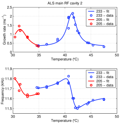
In order to characterize the frequency dependence of the impedance we shifted the center frequencies of the cavity HOM resonances by changing the temperature of the cavity. At each point the temperature was allowed to stabilize and the open-loop eigenvalues of the unstable modes were measured using the transient grow-damp technique. In Fig. 1 the growth rates and oscillation frequencies of modes 205 and 233 are plotted versus temperature of cavity 2.
| Cavity | 1 | 2 | 2 |
|---|---|---|---|
| , GHz | 2.8532 | 2.8532 | 0.8119 |
| , k | |||
| , |
These measurements agree well with the expected effect of the HOM resonators. However these measurements do not provide a way to distinguish between the two possible HOMs at 2.353 and 2.853 GHz as the source of the aliased impedance. To resolve this ambiguity the ring was filled with a single bunch while a cavity probe signal was monitored on a spectrum analyzer. We observed that change of cavity temperature had very small effect on the magnitude of the revolution harmonics excited within the 2.353 GHz resonance while signal at 2.853 GHz scaled with temperature in agreement with the growth rate measurements. Thus the resonance measured in the temperature scan is at 2.853 GHz. In addition the impedance presented by the 2.353 GHz HOM can be considered constant.
In order to quantify impedance parameters and we convert cavity temperatures to center frequencies of the resonance. Conversion factor is determined by matching cavity probe signal levels between two temperatures and two RF frequency settings. Using nonlinear least-squares estimation we extract parameter values. In Table 1 results for both cavities are summarized. Note that characteristics of the 2.853 GHz resonances in two cavities differ significantly. The cavities have RF windows of different designs which can cause variations in the values. Additionally, the mode in question is close to the beam pipe cut-off frequency and is strongly affected by the field leakage.
Using growth rates vs. RF cavity temperature results it is possible to optimize operating temperatures of the main RF cavities. Since temperatures affect the transverse impedances as well as longitudinal impedances, mapping growth rates in horizontal and vertical planes is necessary for a full understanding of the tradeoff.
5 BESSY-II measurements
These measurements were aimed at quantifying longitudinal impedances at BESSY-II. The machine was filled with 350 consecutive bunches out of 400 to a current of 165 mA. A series of 15 transient grow/damp experiments was conducted over a period of 10 minutes during which the machine configuration remained unchanged. There are three unstable EFEMs seen in the data: 281, 396, and 397. Using Eq. 1 we extract complex longitudinal impedances from the measured growth rates and oscillation frequencies.
Impedance measurement for modes 396 and 397 correlates well with the impedance of four third harmonic cavities parked between 3 and 4 revolution harmonics below .
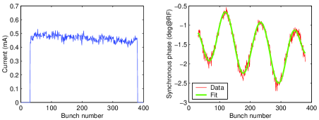
As described in Sec. 3 we can estimate the impedance by analyzing the synchronous phase transient. In Fig. 2 synchronous phase transient in BESSY-II is presented with 350 consecutive buckets filled nearly equally. Periodic pulse excitation of the fill pattern generates oscillatory behavior of the synchronous phases. Solving Eq. 3 in the least-squares sense we obtain aliased impedances. Least-squares estimate of the synchronous phases is also shown in Fig. 2 for comparison with experimental data. Using 15 BESSY transient measurements described above we get k and k.
The two methods of measuring the impedance can be used together in order to determine unaliased frequencies. This is possible due to the fact that during aliasing into impedance is scaled by resonant frequency, while in it is unscaled. From Eq. 2 we have
| (4) | |||||
Since in Eq. 4 is an integer by definition, comparison above indicates that the physical impedance is at . This conclusion agrees perfectly with the expected position of the parked third-harmonic cavities.
6 Summary
We have demonstrated several methods for measuring the impedance of accelerator components using transient diagnostic capabilities of the DSP-based longitudinal feedback systems. The methods extend the capabilities of laboratory bench measurements by quantifying the physical impedances as installed in the accelerator. Dependence of the impedances on operating conditions such as temperature or tuner position can be extracted and used to select optimal working points. By comparing information obtained from growth transients with the analysis of the synchronous phase transients for uneven fills it is possible to determine the spectral position of the driving impedance.
7 Acknowledgments
Authors would like to thank Jorn Jacob of ESRF and Greg Stover of LBNL for help in setting up and conducting ALS measurements. We also thank Shaukat Khan and Tom Knuth for setting up and taking BESSY-II transient measurements.
References
- [1] L. Palumbo and V. G. Vaccaro, in Frontiers of Particle Beams: Observation, Diagnosis and Correction (Springer-Verlag, Berlin, 1989), pp. 312–354.
- [2] J. N. Corlett and J. M. Byrd, in 1993 IEEE Particle Accelerator Conference: proceedings (IEEE, Piscataway, NJ, USA, 1994), pp. 3408–3410.
- [3] A. Hofmann and B. Zotter, IEEE Trans. Nucl. Sci. 24, 1487 (1977).
- [4] S. Prabhakar, Ph.D. thesis, Stanford University, 2000, SLAC-R-554.
- [5] J. Fox et al., in Proceedings of the 1999 Particle Accelerator Conference (IEEE, Piscataway, NJ, USA, 1999), pp. 636–640.
- [6] S. Prabhakar, J. D. Fox, D. Teytelman, and A. Young, Phys. Rev. ST Accel. Beams 2, 084401 (1999).
- [7] S. Prabhakar et al., in Proceedings of the Sixth European Particle Accelerator Conference (IOP Publishing, Bristol, 1998), pp. 996–998.
- [8] S. Prabhakar et al., Part. Accel. 57, 175 (1997).