New 357 MHz Sub Harmonic Buncher
Abstract
KEK-ATF is doing R&D establishing high-current and low-emittance electron beam for the future linear colliders. In ATF, 15 ps length electron beam is generated by combination of a thermionic gun, a couple of 357 MHz SHBs, and a S-band TW buncher. In the linac, beam instability caused by the fluctuated amplitude and phase of SHBs has been observed. The reason of the fluctuation is considered to be the multi-pacting in the SHB cavity. In addition, Q value of the cavity is almost half of the designed value, then SHBs are not operated in an optimum condition. We have fabricated new SHBs with considerations avoiding the multi-pacting and recovering Q value. A simulation shows that bunching quality is improved with the new SHB cavity.
1 Introduction
KEK-ATF is a test facility to study the low-emittance multi-bunch beam and beam instrumentation technique for the future linear collider. That consists from 1.5 GeV S-band linac, a beam transport line, a damping ring, and a diagnostic extraction line.
In the linac, the electron beam is generated by a thermionic electron gun. Typical intensity is electron/bunch. The bunch length shrinks from 1 ns to less than 20 ps by passing a couple of sub-harmonic bunchers and a TW buncher. The electron beam is accelerated up to 1.3 GeV by 8 of the S-band regular accelerating sections.
In April 2000, we achieved horizontal emittance , vertical emittance (both for , single bunch mode )[1] which are almost our target.
In November 2001, we have started the multi-bunch beam operation. 20 of bunches separated by 2.8 ns are accelerated by one RF pulse. This multi-bunch method is one of the key technique in the linear collider. The commissioning was successfully done. electron/train was obtained at the extraction line. We now struggle to develop many instrumentation devices to measure the multi-bunch profile clearly.
In ATF, the instability of the injection part of the linac has been an issue. From a study, the amplitude and phase fluctuation of SHB cavities are one of the reason of the instability.
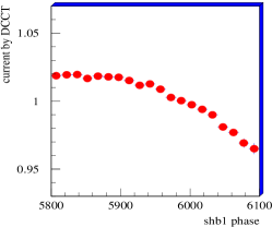
Fig. 1 shows the ring current measured by DCCT as function of phase of SHB1 RF. Both variables are normalized by average of itself. From this figure, the SHB1 phase makes the ring current unstable. Similar property is found on the amplitude and both for SHB2 too.
In single bunch operation, the injection instability changes only the beam current. On the ohter hand, in case of multi-bunch operation, it changes not only the total current, but also the bunch by bunch profile. Response of most of the instrumentation device such as BPM depends on the bunch by bunch profile. The fluctuation causes therefore an extra ambiguity on the measurement. It is currently the most serious problem of the beam instrumentation for the multi-bunch beam.
The instability of the bunching system extends the bunch length leading large energy spread. The injection efficiency to the ring becomes therefore worse. To examine the stability of the bunching system, the bunch length is a good index rather than the injection current.
In ATF, a device to measure the bunch length has been placed at the end of the injector part. This device, so called Bunch Length Monitor, BLM detects amplitude of 6.5 GHz and 11.4 GHz signals induced by beam. Bunch length is reconstructed from the both information.
Tab. 1 shows contributions from various sources on the bunch length instability. The bunch length instability is evaluated as the standard deviation normalized by its average. From these data, phase of SHB1 and amplitude of SHB2 have large contributions. Distribution of SHB2 amplitude has two peaks and this value is calculated for both peaks. If we take only one peak, it becomes 0.0009.
| Source | |
|---|---|
| Gun HV | 0.0012 |
| SHB1 phase | 0.0067 |
| SHB1 amplitude | 0.0034 |
| SHB2 phase | 0.0013 |
| SHB2 amplitude | 0.0097 (0.0009) |
By monitoring RF in the SHB cavity, RF amplitude distortion is observed by multi-pacting. This strong multi-pacting can be suppressed by optimizing magnetic field of Helmholtz coils surrounding the cavities. Even though, these results suggests that weak multi-pacting still exists in SHBs and causes the bunch length instability.
2 New SHB cavity
To stabilize SHB cavity by avoiding multi-pacting, we have newly made SHB cavities. Fig. 2 shows half of the cross sectional view of the new SHB cavity. The bottom of the figure corresponds to the center of the beam line. The cavity design was performed with MAFIA which is a electrical magnetic field simulator.
Comparing to the ordinal pill box cavity, the cavity space is extended to up-stream direction. This geometry composes structure, i.e. the left end of the cavity is close (electrically terminated) and the cavity gap, the right end, works as open end. The benefit of this geometry was clear if the accelerating gap was placed at the center of the cavity. In that case, the cavity length would be twice of the designed to keep same resonant frequency.
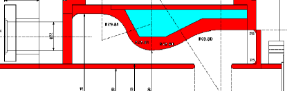
Another tip is the waist at the center of the cavity. Due to the narrow gap at this waist, the electrical field is concentrated here rather than on the accelerating gap. It decreases R/Q of the cavity. Because the beam loading effect is proportional to R/Q, this geometry makes the cavity strong to the beam loading. It is a big advantage for the multi-bunch operation. The designed R/Q is 46.2 .
An important issue on the current SHB cavity is low Q value. The designed Q value is around 8000, but the actual Q value is only 3000. That can be explained by power loss with the contact resistance of copper gasket. The SHB cavity is composed from three parts, barrel and end plates. These parts are assembled with copper gasket vacuum seal. Electrical contact is also made through the gasket with very sharp edges.
In the new SHB cavity, the copper gasket is still used, but the electrical contact is made directly on the inner wall. To make a good electrical contact by keeping vacuum seal, careful turning on the barrel end where electrical contact is made, was performed. The designed Q value for the new SHB cavity is 7800, and the measured value is 7300. By the careful machining, an ideal electrical contact was obtained.

Fig. 3 shows pictures of the new SHB cavity. From left, the up-stream end plate which has a long nose corresponding to the beam pipe, the barrel, and the down-stream end plate. The length of the cavity along the beam direction is 213 mm. The diameter is varied from to . The length of the accelerating gap is 40 mm.
As mentioned in the next section, preventing the multi-pacting is one of the most important purpose of this new SHB. To suppress it, the cavity wall is coated by TiN after taking this picture.
3 Multi-pacting
Multi-pacting is resonant electron emission. Electron emitted from the cavity wall is accelerated by RF field and attacks to the wall again. This initial incident electron would make secondary electron(s). The expectation number of the secondary electron(s) is defined as yield. If the yield is more than unity and this condition is kept during the iterations, number of electron is increased and increased through the chain process. Finally, the cavity RF field is totally distorted by tons of flying electrons. This process is called as multi-pacting.
For a simple geometry like two parallel plates, the multi-pacting is well formalized, but in general cases a simulation is only way to examine it. In design phase, we have therefore perform a simulation to prevent the multi-pacting in SHB.
Assumptions for the simulation are as follows;
-
•
RF field was evaluated by MAFIA.
-
•
Cavity surface is copper (determins the yield).
-
•
The initial momentum of secondary electron is 1/3 of that of the incident electron.111This number is experimentaly evaluated[2].
-
•
Secondary electron is emitted always perpendicular to the cavity surface.
-
•
The simulation is terminated if the yield is less than unity.
-
•
If an electron is still alive after 50 processes, it is defined as a possible multi-pacting condition.
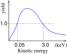
Fig. 4 shows yield of secondary electrons as function of incident electron energy. These data are taken with copper surface baked at 300 temperature[3]. It means that the incident electron with its kinetic energy between 0.05 and 3.0 keV generates more than one secondary electrons leading the multi-pacting.
It is well known that TiN has yield less than that for copper. Because the inner wall of the new SHB cavity is coated by TiN, then this assumption, copper surface is conservative. Real SHB cavity is supposedly stronger to the multi-pacting than the simulated.
With these assumptions, test particles were placed at the cavity wall with 1.0 mm steps and cavity RF phase was scanned with 2.0 deg. step.
There are two types of multi-pacting; one point and two point. Two point multi-pacting occurs between parallel plates, on the other hand, one point multi-pacting occurs on a same plane. As results of the simulation, we have found only one point multi-pacting. Basically, the two point multi-pacting hardly occurs with external magnetic field because the magnetic field breaks the spatial symmetry between two plates.
The place where the one point multi-pacting was found, was the corner edge of the cavity. In such area, the electric field is relatively weak and electron velocity is not so fast, so that it can rotates back to the same plane without hitting other side.
The reason that electric field becomes weak at the corner is boundary condition on a conductor surface; electric field must be perpendicular to the surface. Because conductor surfaces are crossing perpendicular to each other at the corner edge, electric field perpendicular to one surface is parallel to another surface. As the result, electric field is going to be weak by approaching to the corner.Such area where electric field is very weak, can be vanished by rounding the corner edge because electric field perpendicular to the tangent of the rounding arc is allowed.
According to this study, all of the corner of the new SHB cavity is rounded by 5 mm radius. This 5 mm radius was determined since multi-pacting was not found more than 3 mm away from the corner.
4 Bunching quality
Bunching quality which will be obtained by the new SHB cavity was estimated by a simulation. The simulation was performed by using a simulator for particle tracking code accounting the space charge effect, GPT (General Particle Tracking).
Elements set in the simulation were as follows; SHB cavities, a TW buncher, and many Helmholz coils. The position of each element is same as the current ATF setting, i.e. we did not perform any optimization for the position of the elements.
The first and second SHBs are placed at 1.46 m and 2.42 m away from the Gun exit respectively. TW buncher which has 10 cells including the coupling cells is placed at 2.81 m. The magnetic field along the beam axis induced by the Helmholz coils is varied from 0.005 tesla at SHB1 to 0.09 tesla at the exit of TW buncher. Input power for SHB1 and SHB2 are set to be 6.0 and 13.0 kW respectively.
Assuming Q=7300 and R/Q=46 for the new SHB, bunch length on TW buncher exit was obtained as 13.2 ps. This value is enough to fit S-band acceleration.
Assuming Q=3000 and R/Q=45 corresponding to the current SHB, bunch length on TW buncher exit was obtained as 30.0 ps. It is larger than that required by stable S-band acceleration. It may be a reason of the large beam loss at the injection part in ATF.
From this study, the bunching performance will be improved and the transmission will be better by the new SHB cavity.
5 Summary
In ATF, the beam instability caused by injection part has been a big issue. From a correlation study, SHB phase and amplitude fluctuations induce the instability. The most candidate of the mechanism generating such fluctuations is multi-pacting.
The current SHB has another problem that it has only Q value of 3000. That is much lower than the designed value, 7800.
Because of these reasons, we have made newly SHB cavities with careful cosiderations; low R/Q, high Q, preventing multi-pacting.
We have manufactured SHB cavities with Q-value of 7300 which is very close to the designed value, 7800. All of the corner of the inner wall is rounded by 5.0 mm radius suggested by the simulation to prevent multi-pacting.
By a particle tracking simulation, it is expected that the bunching performance and the beam transmission of the injector system is improved.
References
- [1] http://lcdev.kek.jp/ATF/
- [2] A. J. Hatch, NIM 41 (1966)261-271
- [3] R. Calder, G. Dominichini, N. Hilleret, NIM B13 (1986) 631