Novel Ferromagnetic Atom Waveguide with in situ Loading
Abstract
Magneto-optic and magnetostatic trapping is realized near a surface using current carrying coils wrapped around magnetizable cores. A cloud of Cesium atoms is created with currents less than 50 mA. Ramping up the current while maintaining optical dissipation leads to tightly confined atom clouds with an aspect ratio of 1:1000. We study the 3D character of the magnetic potential and characterize atom number and density as a function of the applied current. The field gradient in the transverse dimension has been varied from 10 G/cm to 1 kG/cm. By loading and cooling atoms in-situ, we have eliminated the problem of coupling from a MOT into a smaller phase space.
pacs:
PACS numbers: 32.80.Pj, 03.75.Be, 39.20.+q, 73.63.NmEncouraged by the recent successful demonstration of Bose Einstein condensation in atomic vapors, and the macroscopic coherence properties of this new state of matter, many groups are pursuing the integration of several complex atom-optical devices on a single substrate[1, 2, 3, 4, 5]. Atomic waveguides are likely to be a building block of such atom-optic devices. Magnetic waveguides for atoms have been demonstrated, confining weak field seeking atoms in a local magnetic field minimum. Most guides are based on current carrying wires, either suspended in free space[6, 7], embedded in a tube[8, 9] or lithographically patterned on a substrate[2, 3, 10].
In this paper, we describe a new approach to create magnetic waveguides that transport neutral atoms above the surface of a substrate, by exploiting magnetic materials poled by time dependent currents. This approach has several major advantages over systems that simply use current carrying wires to create the waveguides.
Firstly, the capture volume for collecting atoms from the background vapor can be much larger. For a typical gradient of 10 G/cm, the capture volume for a wire-based guide is about cm2 times the length of the guide. In contrast, the ferromagnetic structures used in our experiment have capture volumes of around 1 cm2 times the length. This is due to the different range of the magnetic potential determined by the size of the structure, 100 m for the wire-based traps and 1 cm in our case. The large capture volume has allowed us to trap a large number of atoms in a magneto-optical trap (MOT) using the same quadrupole field that will be used to form the magnetic waveguide. We transfer the atoms from the MOT into the waveguide by ramping the magnetic field by around 3 orders of magnitude to produce a very high gradient waveguide at the same position as the initial MOT[11] with the transferred atoms remaining cold in all three dimensions. Since all the atoms are loaded in situ, the transfer between the low and high gradient waveguides can be made very efficient. Thus we avoid the more traditional process of dropping or pushing atoms into a tightly confined waveguide which results in inefficient transfer and increase in temperature.
Secondly, the large distance of the center of the waveguide from the surface allows us to protect the atoms from heating due to interactions between the atoms and the surface[12]. Moreover, the high field gradients result in a transverse width of the atom cloud which is much smaller than the distance from the surface. This inhibits losses due to collisions with the surface[1]. Also, any inhomogeneities in the magnetic field due to small imperfections on the surface of the ferromagnetic foils are smoothed out at the location of the waveguide.
Thirdly, the amplification of the magnetic field by the ferromagnetic foils implies a smaller current is required to generate a given peak magnetic field. This results in greatly reduced ohmic heating. In our setup, the ferromagnetic cores amplify the field due to the wires typically by a factor of 50. Thus, the initial gradient of around 7 G/cm for the MOT was realized by running less than 50 mA around the ferromagnetic cores. We have achieved gradients on the order of 1 kG/cm and trap depths of more than 100 G with less than 100 W of dissipation. This reduced heating is important since one of the modes of failure of previous devices based on current carrying wires was the fusing of wires due to local heating when running currents of a few amperes[13].
Finally, these structures permit much larger field gradients and trap depths than can be obtained in systems using only current carrying wires. The peak field at the surface of a ferromagnetic core that is fully poled is equal to the saturation field of that material which ranges from around 4 kG to 20 kG[14]. Steep magnetic traps can be formed by using ferromagnetic structures of suitably small size[15, 16]. This results in a larger compression of the atoms from the initial MOT, leading to higher densities and improved collision rates for evaporative cooling. Also, the large gradients imply tighter confinement and larger ground state energies and mode spacings. Moreover, this would enable us to guide the confined atoms in tight loops permitting the fabrication of reciprocal atom interferometers with large enclosed areas and small length[17, 18]. For instance, our demonstrated gradient of 1 kG/cm would allow us to transport atoms moving at 1 m/s around a loop of radius 6 mm giving an interferometer with an enclosed area larger than 1 cm2.
For a quadrupole potential , the transverse mode spacing is in energy units and the ground state width is given by . We have experimentally achieved 1D magnetic traps with transverse mode spacings of around 10 kHz (0.5 K) and ground state sizes less than 50 nm. The large aspect ratio (1:1000) of the eventual magnetostatic trap realized in our experiment makes this system an attractive candidate for investigation of the Tonk’s gas regime[19]. Similar structures of smaller size, made with ferromagnetic materials of larger saturation fields, should permit gradients of G/cm. The configuration described in this work can also be used to split a waveguide in the transverse dimension with the aid of an external bias field.
A schematic of the experimental setup is shown in Fig.1. Two pairs of ferromagnetic foils (80% Ni, 15.5% Fe, 4.5% Mo) are mounted on a rigid platform at separations of 1 mm. Both pairs of foils are 0.5 mm thick and 5 cm long along the long axis. The inner pair of foils is cut to a height of 1 cm while the outer pair is cut to a height of 2.5 cm. Thin kapton insulated wires are wound around these foils with 9 turns around the inner pair and 25 turns around the outer pair. Depending on the sense of the current around each foil, the foils can be individually magnetized in one of two directions.
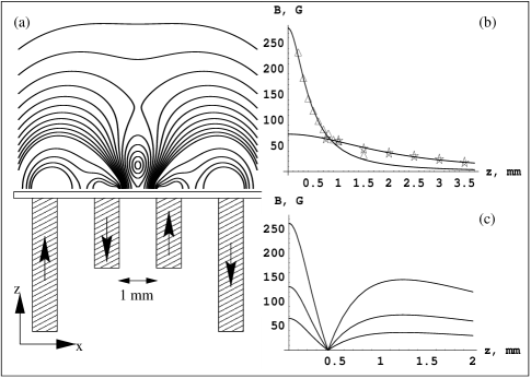
In the situation where the foils are magnetized in opposite directions, the direction of the field at the plane of symmetry due to one pair of foils is completely horizontal and its magnitude varies with height above the surface as[20]
| (1) |
where is the current around the ferromagnetic foils, the number of windings and the height above the surface. , and are the height of the foils, separation between the pair of foils and the thickness of each foil respectively. The dimensionless constant depends on the geometry and material of the ferromagnetic foils and is experimentally found to be around 50.
Due to the geometry of these foils, the potential is very shallow along the long (waveguide) axis and the magnetic trap has a large aspect ratio. A pair of trapping beams perpendicular to the long axis of the waveguide is reflected off a gold coated mirror at an angle of 45∘. This mirror is glued to the surface of the foils as indicated in Fig.1. Another pair of counterpropagating laser beams grazes the mirror surface along the long axis of the guide. This geometry is similar to a mirror MOT[1] but in this case, the quadrupole fields are generated by the ferromagnetic foils underneath the mirror. Additionally, changing the polarization of the laser beams along the guide does not significantly change the number of trapped atoms indicating that the atoms are damped but not trapped in this dimension. The length of the cloud along the waveguide is limited by the waist of the laser beam and equals 1 cm in our case. We emphasize that the MOT in which the atoms are initially loaded and cooled is at the same location as the magnetic waveguide into which the atoms are eventually loaded and compressed.
It is important to characterize the fields generated by the ferromagnetic foils as a function of the current and the height above the surface. This was done by two independent methods.
In the first method, the fields due to the inner and outer pair of foils were determined with a calibrated commercial tape head on a micrometer translation stage. The measurements were performed by running ac currents of 10 mA at a frequency of 150 Hz around the foils. It was verified that the pickup voltage does not depend on the ac frequency. These measurements are shown in Fig.1(b). The calculations in Fig.1(c) show that the gradient can be increased while keeping the trap minimum at the same height above the surface.
Next, the system was placed in a UHV chamber pumped to a typical pressure of mbar. Currents of up to 1A were run around either the inner or the outer pair of foils. By cancelling these fields at the plane of symmetry with an external horizontal field of known magnitude, magneto-optic traps were created at different heights above the surface. At the position of the cloud, the magnitude of the bias field is equal to that of the ferromagnetic foils, by construction. Therefore, this constitutes an alternative calibration of the field as a function of distance to the surface. This measurement using cold atoms shows good agreement with the data in Fig.1(b).
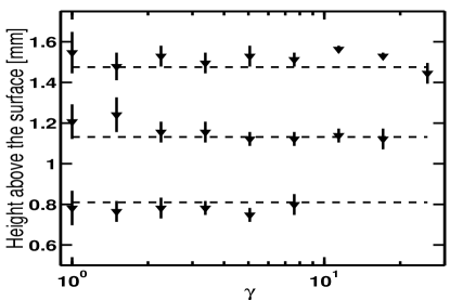
Using an external bias field does not exploit the benefits of the ferromagnetic materials and imposes a limit on the maximum gradient that can obtained. However, MOTs can also be formed by exclusively running currents around the inner and outer pair of foils, without any external bias field. By using the outer pair of ferromagnetic foils to provide the cancelling field, waveguides with larger gradients and trap depths can be realized. Also, the waveguide can be formed without an external field. When and are increased by the same factor , the gradient should increase by without changing the height of the trap as shown in Fig.1(c). To verify this, we have measured the height of the atom cloud above the surface and plotted the results in Fig.2. In this experiment, the ratio were 1/3, 1/2 and 3/4 corresponding to heights of 1.5 mm, 1.1 mm and 0.8 mm respectively. This is in agreement with the previous calibration.
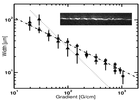
Quantitative information about the temperature and the density of the cloud requires investigating the width of the MOT. Initially, atoms were collected at a gradient of 7 G/cm. Then, and were slowly increased in proportion. After 20 ms, the cloud was imaged on a CCD camera to determine the half width at half maximum (HWHM). Assuming that the transverse motion of the atoms is in equilibrium with the initial temperature, the transverse width of the magneto-optic trap where , the spring constant of the magneto-optic trap is linearly proportional to the gradient . Thus, . An investigation of the transverse widths of the MOT and the magnetic trap for a wide range of gradients (Fig.3) shows excellent agreement with this model. To our knowledge, this large dynamic range (almost 3 orders of magnitude) has not been achieved in a waveguide before. We have also investigated the width of the cloud in the magnetostatic trap. In this case, the laser beams were switched off 3 ms after ramping the currents. After a dark period of 100 ms, the MOT beams were switched on to image the cloud for 6 ms. For adiabatic compression, we expect the width to scale as for a linear potential and for a harmonic potential. However, assuming that the MOT beams cool the cloud to its initial temperature, the width should scale as for a linear potential. As indicated by the dotted line in Fig.3, this is the case in the regime 10 200 G/cm. Above 200 G/cm, the oscillation period of atoms in the MOT is smaller than the camera exposure time, restoring the MOT width. Similar results were obtained when the gradient of the magnetostatic trap was increased in the dark. Assuming an equal distribution of states, the transverse temperature is calculated to be approximately 20 K. These data suggest that dissipation can be maintained well into the regime of collisional loss[21].
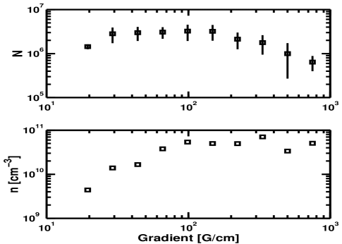
The number of atoms in the elongated atom clouds is deduced from the fluorescence images. Due to the small transverse size of the atom clouds, a commercial parfocal zoom lens (VZM 450) is used for magnification. The solid angle of this lens and the efficiency of the CCD chip were measured in a separate experiment. The scattering rate of atoms in the MOT was calculated using the experimental parameters for the laser intensity and detuning, averaging over the Clebsch Gordon coefficients. The variation of atom number with the gradient is shown in Fig.4. This data can be combined with the transverse width of the atom clouds to estimate the peak density at the various gradients. It can be seen that the density saturates at large gradients. This feature has been observed in 3D traps[22], and is due to multiple photon scattering. The number of atoms decreases at the higher gradients due to light induced collisional losses. Increasing the detuning and decreasing the intensity of the trapping light as the gradient is ramped up should improve the number of trapped atoms.
In conclusion, we have demonstrated direct loading of atoms into a ferromagnetic waveguide with large gradient and trap depth. Our measurements of the magnetic fields, both with an audio tape head and with a cold atom cloud, agree well with a simple model. Due to the large relative permeability, ferromagnetic materials offer the possibility of reaching large energy splittings between vibrational states. This large gap may be important to preserve coherence during matter wave transportation and to facilitate cooling. By applying an external bias field in the system described, we have also demonstrated a bifurcation of the trapping potential to form a double well[23]. This results in an experimentally observed splitting of the elongated cloud in the transverse dimension which is coherent in the adiabatic limit. An atom interferometer in time may be formed by applying a nonadiabatic phase shift to one of the arms[24].
Our system also permits a long guide ( 1 m), where cold atoms are continuously injected at one end, and evaporative cooling is performed along the guide. Dalibard and coworkers[25] have proposed a similar system to create a cw atom laser. Our experiments offer prospects of creating Bose condensates on a substrate on a much shorter time scale or even continuously.
The authors gratefully acknowledge valuable discussions with N. H. Dekker, S. A. Lee and G. Zabow. We are indebted to T. Deng for preparing ultrathin gold mirrors. This work was supported by National Science Foundation Grant Numbers: PHY-9876929 and PHY-0071311 and MURI Grant Number: Y-00-0007.
REFERENCES
- [1] J. Reichel, W. Hänsel and T.W. Hänsch, Phys. Rev. Lett. 83, 3398 (1999).
- [2] R. Folman, P. Krüger, D. Cassettari, B. Hessmo, T. Maier and Jörg Schmiedmayer, Phys. Rev. Lett. 84, 4749 (2000).
- [3] D. Müller, D. Anderson, R. Crow, P. Schwindt and E. Cornell, Phys. Rev. Lett. 83, 5194 (1999).
- [4] J. Thywissen, M. Olshanii, G. Zabow, M. Drndic, K. Johnson, R. Westervelt and M. Prentiss, Eur. Phys. J, D7, 361 (1999).
- [5] E. Hinds and I. Hughes, J. Phys. D: Appl. Phys. 32, R119 (1999).
- [6] J. Fortagh, A. Grossmann, C. Zimmermann and T. Hänsch, Phys. Rev. Lett. 81, 5310 (1998).
- [7] J. Denschlag, D. Cassettari and J. Schmiedmayer, Phys. Rev. Lett. 82, 2014 (1999).
- [8] M. Key, I. Hughes, W. Rooijakkers, B. Sauer, E. Hinds, D. Richardson and P. Kazansky, Phys. Rev. Lett. 84, 1371 (2000).
- [9] B.Teo and G. Raithel, Phys. Rev. A63, 031402 (2001).
- [10] N. Dekker, C. Lee, V. Lorent, J. Thywissen, S. Smith, M. Drndic, R. Westervelt and M. Prentiss, Phys. Rev. Lett. 84, 1124 (2000).
- [11] This 2D trapping, transfer and compression is analogous to the 3D trapping, transfer and compression process used to create most Bose condensates.
- [12] C. Henkel and M. Wilkens, Europhys. Lett. 47, 414 (1999).
- [13] M. Drndic, K. Johnson, J. Thywissen, M. Prentiss and R. Westervelt, Appl. Phys. Lett. 72, 2906 (1998).
- [14] R. O’Handley, Modern Magnetic Materials, published by Wiley Interscience (2000).
- [15] V. Vuletic, T. Fischer, M. Praeger, T. Hänsch and C. Zimmermann, Phys. Rev. Lett. 80, 1634 (1998).
- [16] V. Vuletic, T. Hänsch and C. Zimmermann, Europhys. Lett. 36, 349 (1996).
- [17] A. Lenef, T. Hammond, E. Smith, M. Chapman, R. Rubenstein and D. Pritchard, Phys. Rev. Lett. 78, 760 (1997).
- [18] T. Gustavson, P. Bouyer and M. Kasevich, Phys. Rev. Lett. 78, 2046 (1997).
- [19] M. Olshanii, Phys. Rev. Lett. 81, 938 (1998).
- [20] This expression is valid in the limit . An exact expression can be found in T. J. Davis, J. Opt. B: Quantum Semiclass. Opt. 1, 408 (1999).
- [21] A. Gallagher and D. Pritchard, Phys. Rev. Lett. 63, 957 (1989).
- [22] W. Petrich, M. H. Anderson, J. R. Ensher and E. A. Cornell, J. Opt. Soc. Am. B, 11, 1332 (1994).
- [23] W. Rooijakkers, M. Vengalattore and M. Prentiss (to be published).
- [24] E. Hinds, C. Vale and M. Boshier, Phys. Rev. Lett. 86, 1462 (2001).
- [25] E. Mandonnet, A. Minguzzi, R. Dum, I. Carusotto, Y. Castin and J. Dalibard, Eur. Phys. J. D 10, 9 (2000).