An Improved Empirical Equation for Bunch
Lengthening
in Electron Storage Rings
J. Gao
Laboratoire de L’Accélérateur Linéaire,
IN2P3-CNRS et Université de Paris-Sud, BP 34, 91898 Orsay cedex, France
Abstract
In this paper we propose an improved empirical equation for the bunch lengthening in electron storage rings. The comparisons are made between the analytical and experimental results, and the agreements are quite well. This improved equation can be equally applied to the case where a storage ring is very resistive (such as the improved SLC damping rings) instead of inductive as usual.
1 Introduction
From what we know about the single bunch longitudinal and transverse instabilities [1][2], it is clear to see that the information about the bunch lengthening, , with respect to the bunch current is the key to open the locked chain of bunch lengthening, energy spread increasing and the fast transverse instability threshold current. In this paper an improved (compared with what we have proposed in ref. 3) empirical bunch lengthening equation is proposed as follows:
| (1) |
where
| (2) |
| (3) |
is the single particle ”bunch length”, is the bunch total longitudinal loss factor for one turn at , and are the resistive and inductive part of the machine impedance, respectively, is the inductance of the ring for one turn, is the permittivity in vacuum, is Planck constant, is the velocity of light, , is the particle number inside the bunch, and is the average radius of the ring. Obviously, if one has , which is the case for the most existing storage rings. If SPEAR scaling law [8] is used (for example), (in fact each machine has its own ), eq. 1 can be written as
| (4) |
In fact, the third term of eqs. 1 is due to the Collective Random Excitation effect revealed in ref. 1, except a new factor which is introduced in this paper to include the special case where has the same order of magnitude or even less than . The second term, however, is obtained intuitively as explained in section 3. Now we make more discussions on and . Being aware of the possible ambiguity coming from this frequently used term in the domain of collective instabilities in storage rings, we define and used in this paper as follows:
| (5) |
and
| (6) |
where , , , and is the particle revolution period. By using eqs. 5 and 6 one gets explicit expression of shown in eq. 3.
The procedure to get the information about the bunch lengthening and the energy spread increasing is firstly to find by solving bunch lengthening equation, i.e., eq. 1, and then calculate energy spread increasing, (), by putting into eq. 7 [1]:
| (7) |
Once is found, one can use the following formula to calculate the fast single bunch transverse instability threshold current [2]:
| (8) |
with
| (9) |
where and are synchrotron and vertical betatron oscillation tunes, respectively, is the average beta function in the rf cavity region, is the chromaticity in the vertical plane (usually positive to control the head-tail instability), is the total transverse loss factor over one turn, is the natural energy spread, and is the particle energy. In practice, it is useful to express as , where is the value at the natural bunch length, and is a constant depending on the machine concerned. As a Super-ACO scaling law, can be taken as [4]. Eq. 8 is therefore expressed as:
| (10) |
The notation is used with the aim of distinguishing it from the formula given by Zotter [5][6].
2 Comparison with Experimental Results
In this section we look at seven machines
with their parameters shown in table 1.
| Machine | (m) | (m) |
|---|---|---|
| INFN-A | 1.15 | 5 |
| ACO | 1.11 | 3.41 |
| SACO | 1.7 | 11.5 |
| KEK-PF | 8.66 | 29.8 |
| SPEAR | 12.7 | 37.3 |
| BEPC | 10.345 | 38.2 |
| SLC Damping Ring | 2.037 | 5.61 |
The machine energy, natural bunch length and the corresponding longitudinal
loss factor are given in table 2.
| Machine | (cm) | (V/pC) | |
|---|---|---|---|
| INFN-A | 998 | 3.57 | 0.39 |
| ACO | 467 | 21.7 | 0.525 |
| SACO | 1566 | 2.4 | 3.1 |
| KEK-PF | 3523 | 1.1 | 5.4 |
| KEK-PF | 4892 | 1.47 | 3.7 |
| SPEAR | 2935 | 1 | 5.2 |
| BEPC | 2544 | 1 | 9.6 |
| BEPC | 3953 | 2 | 3.82 |
| SLC Damping Ring | 2329 | 0.53 | 12 |
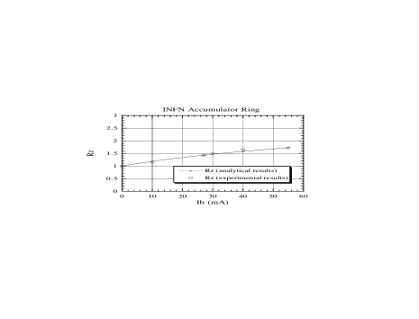
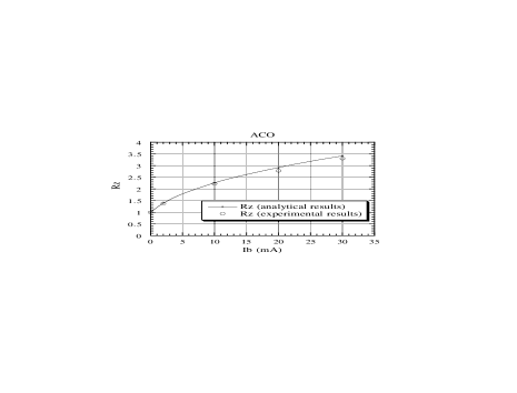
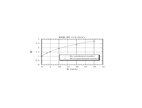
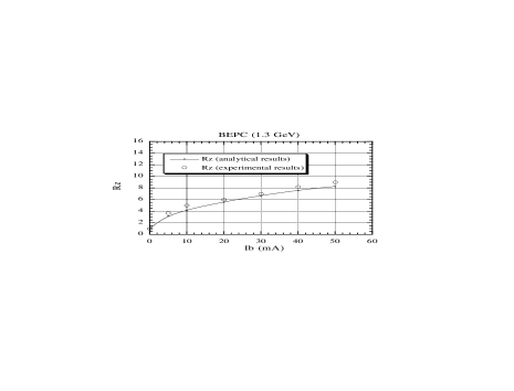
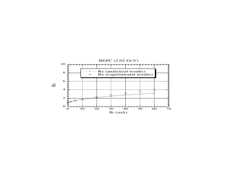
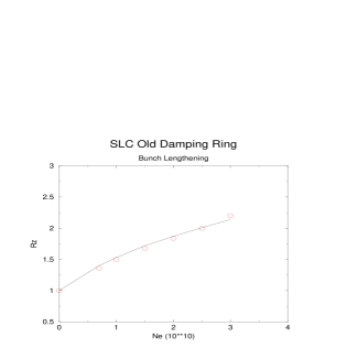
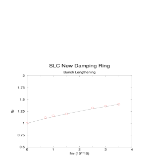
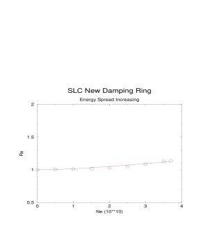
Concerning the loss factors, that of INFN accumulator ring comes from ref. 6 and the others are obtained by fitting the corresponding experimental results with the bunch lengthening equation given in ref. 1. Figs. 1 to 10 show the comparison results between the analytical and the experimental [8]-[18] bunch lengthening values, and Fig. 11 shows the single bunch energy spread increasing. It is obvious that this improved empirical bunch lengthening equation is quite powerful. Among the seven different storage rings, SLC new damping ring is the unique and the most interesting one since it is a very resistive ring [16], on the contrary, the other rings including SLC old damping ring are quite inductive. The inductances of the old and the new SLC damping rings are 33 nH and 6 nH, respectively [17]. By fitting the bunch lengthening experimental results, one finds that the loss factor equals 12 V/pC at cm (this value is put in table 2), which agrees quite well with the experimentally measured loss factor, 15 V/pC, at the same bunch length [18]. From Fig. 11 one can see that the single bunch energy spread increasing in SLC new damping ring is rather accurately predicted by eq. 7.
3 Discussion
In fact eq. 1 can be obtained from the following equation by truncating the Taylor expansion of the right hand side of eq. 11 up to the second order.
| (11) |
From the point of view of aesthetics, eq. 11 is more attractive (at least for the author). Even if it doesn’t work well itself, this equation is instructive for us to establish the second term in eq. 1.
4 Conclusion
In this paper we propose an improved empirical bunch lengthening equation and compare the analytical results with the experimental results of seven different machines where SLC new damping ring is quite resistive. The agreement between the analytical and experimental results is quite satisfactory. The factor introduced in this paper should be included (one should multiply it to ) into the corresponding formulae in ref. 1 also in order to be applied to the case where a storage ring is very resistive.
5 Acknowledgement
The author thanks J. Le Duff and J. Haïssinski for their critical comments and interests in this subject. I have enjoyed the interesting discussions on SLC damping rings with K. Bane, B. Podobedov, A. Chao, G. Stupakov, S. Heifets, and some other theory club members at SLAC.
References
- [1] J. Gao, “Bunch lengthening and energy spread increasing in electron storage rings”, Nucl. Instr. and Methods, A418 (1998), p. 332.
- [2] J. Gao,“Theory of single bunch transverse collective instabilities in electron storage rings”, Nucl. Instr. and Methods, A416 (1998), p. 186.
- [3] J. Gao,“An empirical equation for bunch lengthening in electron storage ring”, Nucl. Instr. and Methods, A432 (1999), p. 539.
- [4] P. Brunelle,“Etude théorique et expérimentale des faisceaux dans l’anneau VUV SUPER-ACO”, thèse, Université Paris 7, 1990.
- [5] B. Zotter, “Mode-coupling or “transverse turbulence” of electron or positron bunches in the SPS and LEP”, LEP note 363 (1982).
- [6] B. Zotter, “Current limitations in LEP due to vacuum chamber bellows”, LEP note 528 (1985).
- [7] M. Migliorati and L. Palumbo, “Wake field energy spread and microwave instability”, Proceedings of ICFA Beam Dynamics Workshop, Frascati, Oct. 20-25, 1997, p. 347.
- [8] P.B. Wilson, R. Servranckx, A.P. Sabersky, J. Gareyte, G.E. Fischer, A.W. Chao, and M.H.R. Donald, “Bunch lengthening and related effects in SPEAR II”, IEEE Trans. on Nucl. Sci. NS-24 (1977) p. 1211.
- [9] R. Boni, et al., “Bunch lengthening and impedance measurements and analysis in DANE accumulator ring”, Note: BM-1, Frascati, March 10, 1997.
- [10] Le groupe de l’anneau de collisions d’Orsay, “Allongement des paquets dans ACO”, Rapport technique 34-69, Orsay, le 14 novembre (1969).
- [11] A. Nadji, et al., “Experiments with low and negative momentum compaction factor with Super-ACO”, Proceedings of EPAC96, Barcelona (1996) p. 676.
- [12] N. Nakamura, S. Sakanaka, K. Haga, M. Izawa, and T. Katsura, “Collective effects in single bunch mode at the photon factory storage ring”, Proceedings of PAC91, San Francisco, CA (1991) p. 440.
- [13] SPEAR Group, “SPEAR II performance”, IEEE Trans. on Nucl. Sci.NS-22 (1975) p. 1366.
- [14] Z. Guo, et al., “Bunch lengthening study in BEPC”, Proceedings of PAC95, Dallas TX (1995) p. 2955.
- [15] K. Bane, “The calculated longitudinal impedance of the SLC damping rings”, SLAC-PUB-4618, 1988.
- [16] K. Bane and K. Oide, “Simulations of the longitudinal instability in the new SLC damping rings”, SLAC-PUB-6878, 1995.
- [17] K. Bane, et al., “High-intensity single bunch instability behaviour in the new SLC damping ring”, SLAC-PUB-6894, 1995.
- [18] B. Podobedov and R. Siemann, “New apparatus for precise synchronous phase shift measurements in storage rings”, SLAC-PUB-7939, 1998.