Air entrainment through free-surface cusps
Abstract
In many industrial processes, such as pouring a liquid or coating a rotating cylinder, air bubbles are entrapped inside the liquid. We propose a novel mechanism for this phenomenon, based on the instability of cusp singularities that generically form on free surfaces. The air being drawn into the narrow space inside the cusp destroys its stationary shape when the walls of the cusp come too close. Instead, a sheet emanates from the cusp’s tip, through which air is entrained. Our analytical theory of this instability is confirmed by experimental observation and quantitative comparison with numerical simulations of the flow equations.
=0.5 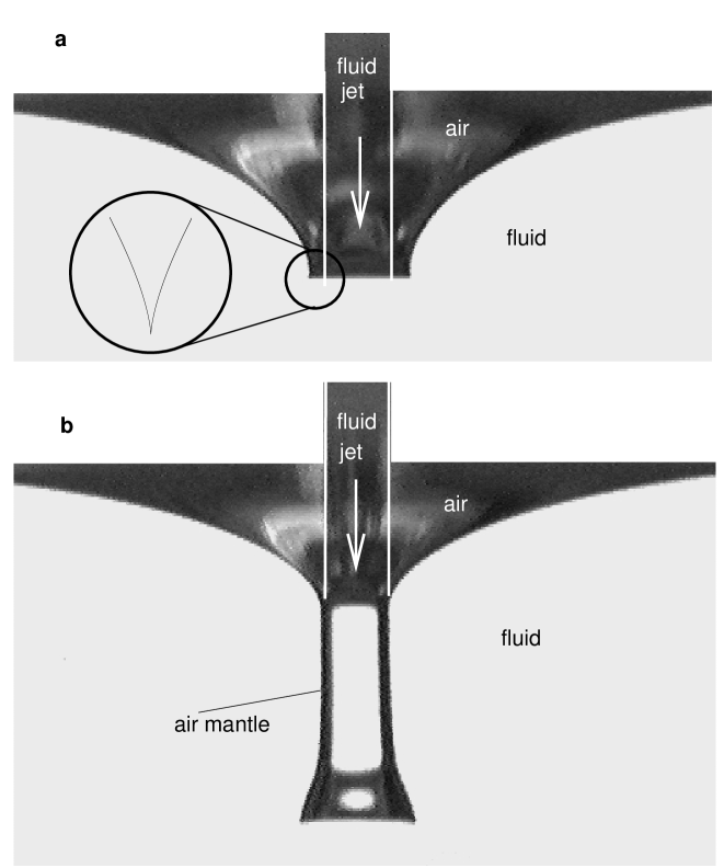
Air bubbles are a ubiquitous presence in fluid flow, appearing when pouring a liquid into a beaker, when beating an egg, or in river streams. This aeration is often desirable, for example to promote chemical reactions [1], yet in many industrial processes entrainment of air bubbles is detrimental to the quality of the product, rendering the flow unsteady. For example, it is the single most important factor limiting the speed at which paints or coatings can be applied to a solid surface [2, 3]. But in spite of its importance, no general understanding of air entrainment exists, except for the rather special circumstance that the free surface conspires to enclose an air bubble from all sides, as was recently found for a disturbed water jet [4]. Instead, here we argue that the presence of cusp singularities on the free surface results in a generic mechanism for air entrainment.
In recent years it has emerged that free surfaces are rather susceptible to the formation of sharp tips or cusps [3, 5, 6, 7]. This is true in particular for viscous fluids, where shear stresses are strong compared with surface tension forces [7]. Examples are drop impact on a surface [10], jets impinging on a pool of liquid [1], and the coating of a pre-wetted solid cylinder [3]. Once the air enters these narrow passages, the gas flow serves to destroy the original structure to let the air penetrate below the surface. What is surprising about this novel mechanism is that the forces the gas flow exerts on the fluid plays the crucial role, even though the viscosity of the air may be smaller by many orders of magnitude than that of the fluid. Other instabilities may occur at a three-phase boundary, for example when the solid to be coated is dry, a problem studied in [2, 8]. In the presence of surfactant, still another mechanism for the instability of a cusp has been suggested by Siegel [9].
For purposes of illustration, consider the particular example of a two-dimensional cusp that forms when a thin stream of a viscous silicone oil is poured into a container of the same fluid. Since the falling liquid drags other fluid away from the surface, a dip is produced around the fluid stream. Increasing the flow rate above a critical value, this dip is no longer smooth, but a singular point on the surface is approached with two vertical tangents. A cross section of this cusped profile is shown as a black silhouette in Fig.1a, the outer wall of the free surface ending in a vertical tangent at the cusp point. For clarity, the lighting is chosen such that the free surface appears opaque, so the falling jet is only indicated symbolically to guide the eye, but not visible directly.
Increasing the flow rate still further, there is a second critical value where the stationary profile of Fig.1a ceases to exist and a sheet of air shoots out from the tip of the cusp. The bottom picture shows this dynamical structure 1/60th of a second after the cusp has become unstable. A thin air sheet now forms the wall of a transparent fluid cylinder. The details of this dynamical structure, such as the bell-shaped opening at its lower rim, is not the subject of this paper, but only the instability of the static shape leading to it. The cylinder eventually grows to about ten times the length shown, and is unstable to the formation of bubbles at its lower end, so the liquid pool quickly becomes contaminated by bubbles of a broad variety of sizes.
=0.4 
Since the air sheet near the cusp is of micron size, the curvature with which it is wrapped around the impinging jet is of no consequence and the cusp can be viewed as a two-dimensional object. In this spirit, Joseph et al. [6] performed experiments with a two-dimensional flow produced by two counter-rotating cylinders submerged below the surface of a very viscous liquid. If the cylinders are placed sufficiently close to each other, a cusp forms in a symmetrical position between the cylinders [7]. Letting the distance between the rollers going to zero, Jeong and Moffatt found a family of exact solutions to this problem, obeying the local scaling form
| (1) |
where is the curvature at the tip (see Fig.2). The structure of the solution (1) is typical for flows near singularities [11, 12, 13], which involve very small scales. Physically (1) means that the shape of the interface is independent of scale, up to a rescaling of the axes. The other crucial property of singularities is that their shape is universal, i.e. independent of the particular type of flow that generates the cusp. Thus our theory, based on the stability of such a singular structure, will be equally general. Indeed, Antonovskii [14] discovered yet another class of exact solutions, but where the cusp is formed on the surface of a circular bubble. A local analysis reveals that the scaling function
is identical to the one in [7] except for a different value of the numerical constant , confirming the expectation that the flow on small scales is universal, independent of the particular features of the driving flow.
In all solutions, the tip curvature grows exponentially with the capillary number , where is the fluid viscosity, the surface tension, and is a typical velocity scale of the external flow. Thus as the strength of the driving flow increases relative to the surface tension, the size of the tip may easily reach microscopic dimensions [7] if the effect of the air is not taken into account. Without it, stable solutions are thus predicted to exist for all capillary numbers, in disagreement with experiment. Moffatt suggested [15] that this is because all previous analyses neglect the viscosity of the air being drawn into the cusp by the flow parallel to the cusp surface. The air entering a narrow space and having to escape again generates a so-called lubrication pressure inside the cusp, whose derivative with respect to the distance from the cusp is
| (2) |
by Reynolds’ theory [16]. Since the cusp narrows like , the lubrication pressure pushes the walls apart according to , just as it would keep separated to narrowly spaced mechanical parts.
Figure 3 proves by direct numerical simulation that this is enough to destroy the stationary solution found for . We use a boundary integral code [17, 18], optimized to resolve the cusp between two merging cylinders [19], neglecting the fluid inertia. Starting from Antonovskii’s solution with , is increased in steps of , pushing the interface forward,but only every fourth profile is shown. At , no more stationary solution is found, but instead air enters the fluid forming a narrow sheet, as seen in Fig. 1 and observed in earlier experiments [20] An important consequence is that in a physically correct description which incorporates the effect of the air (or some other gas atmosphere), molecular dimensions are never reached, so continuum theory remains valid throughout [21].
To describe the influence of the air analytically, note that the extra transverse velocity field generated by the air pressure can simply be added to as given in [7], since Stokes’ equation is linear. Geometrically, the cusp looks like a two-dimensional crack entering the fluid, a problem well studied in linear elasticity [22]. Borrowing Muskhelishvili’s result, we can now write as
| (3) | |||
| (4) |
=0.4 
But our free-surface problem is of course non-linear, since the free surface has to follow the streamlines of the flow, which are modified by . Namely, the inverse slope of the interface is
| (5) |
where and are known [7] and is calculated from as outlined above. Note that while has to point inward towards the cusp, results from the lubrication pressure and points away from the cusp. Thus, at a given distance from the tip, becomes smaller and the channel narrows. Owing to (2) the lubrication pressure is increased, further increasing , so this nonlinear feedback eventually destroys the cusp solution, as seen in Fig. 3.
It is extremely useful to recast equations (2)-(5) in the scaling variable , cf. (1). First, from (5) and since is a constant up to logarithmic corrections, must scale like . From (2) is estimated as , and thus from integrating once. The two opposing velocities become comparable at some critical value of the parameter . Thus (2)-(5) can be recast in similarity variables, leading to an integral equation for the correction to the unperturbed surface profile :
| (6) |
where . It is a simple matter to solve (6) numerically, giving increasingly large corrections to the profile as is raised. Since is negative, the denominator in the integrand of (6) decreases, leading to a further increase in the absolute magnitude of the correction, in accordance with the qualitative argument given above. Owing to this nonlinear feedback, a solution ceases to exist above a critical value of , which has a weak dependence on due to the logarithmic dependence of on its argument. Hence for the flow parameters of Fig. 3, we predict that the cusp becomes unstable when the curvature reaches a critical value of . This approximation is hardly distinguishable from the result of the full solution of (6), which in the insert of Fig. 3 is seen to be in good agreement with numerical simulations for various values of . Because of the relationship between curvature and capillary number, this translates into the anticipated critical value above which stationary solutions are no longer found. At low viscosities, the capillary number never even reaches the critical value for the formation of a cusp, so an unperturbed water jet does not entrain air [4].
In conclusion, we have incorporated the effect of an outer fluid like air into the theoretical description of a cusp. This allows for the first quantitative description of air entrainment through surface singularities. A description of the resulting sheet of air and its stability remains to be done. Other future challenges include the analysis of its close three-dimensional relatives, namely jet formation out of bubble tips “tip-streaming” [23], Taylor cones “electric jets” [24], or spouts formed by planar interfaces “selective withdrawal” [25].
Acknowledgements.
I am very grateful to Keith Moffatt for pointing out this problem to me, and to Itai Cohen for donating his experimental pictures. Thanks are also due to Todd Dupont for help with the numerics, and to Howard Stone for very useful discussions.REFERENCES
- [1] A.K. Bin, Chem. Eng. Sc. 48, 3585 (1993).
- [2] P.G. Simpkins and V.J. Kuck, Nature 403, 641 (2000).
- [3] B. Bolton and S. Middleman, Chem. Eng. Sc. 35, 597 (1980).
- [4] C.D. Ohl, H.N. Oguz and A. Prosperetti, Phys. Fluids 12, 1710 (2000).
- [5] S. Richardson, J. Fluid Mech. 58, 475 (1968).
- [6] D.D. Joseph, J. Nelson and M. Renardy, Y. Renardy, J. Fluid Mech. 223, 383 (1991).
- [7] J.-T. Jeong and H. K. Moffatt, J. Fluid Mech. 241, 1 (1992).
- [8] I.N. Veretennikov, A.E. Indeikina and H.-C. Chang, talk presented at the ICTAM 2000 meeting in Chicago, IL, 1 September 2000.
- [9] M. Siegel, SIAM J. Appl. Math 59, 1998 (1999).
- [10] D.A. Weiss and A.L. Yarin, J. Fluid Mech. 385, 229 (1999).
- [11] J. Eggers, Rev. Mod. Phys. 69, 865 (1997).
- [12] X.D. Shi, M.P. Brenner and S.R. Nagel, Science 265, 219, (1994).
- [13] B.W. Zeff, B. Kleber and J. Fineberg, D.P. Lathrop, Nature 403, 401 (2000).
- [14] L.K. Antonovskii, J. Fluid Mech. 327, 325 (1996).
- [15] H.K. Moffatt, priv. comm. (1995).
- [16] O. Reynolds, Philos. Trans. R. Soc. London 177, 157 (1886).
- [17] J.M. Rallison and A. Acrivos, J. Fluid Mech. 89, 191 (1978).
- [18] C. Pozrikidis, J. Fluid Mech. 357, 29 (1998).
- [19] J. Eggers, J.R. Lister and H.A. Stone, J. Fluid Mech. 401, 293 (1999).
- [20] H.K. Moffatt (priv. comm.) reports a thin but stable sheet of air penetrating the fluid from the cusp. At its lower end, it undergoes a three-dimensional instability and decays into tiny bubbles.
- [21] Y.D. Shiikhmurzaev, J. Fluid Mech. 359, 313 (1998).
- [22] N.I. Muskhelishvili, Some Basic Problems of the Mathematical Theory of Elasticity, (P. Noordhoff, 1953). [third edition]
- [23] J.D. Sherwood, J. Fluid Mech. 144, 281 (1984).
- [24] A.G.Bayley, Electrostatic Spraying of Liquids, (Wiley, New York , 1988).
- [25] T.J. Singler and J.F. Geer, Phys. Fluids A 5, 1156 (1993).