A monitor of beam polarization profiles for the TRIUMF parity experiment
Abstract
TRIUMF experiment E497 is a study of parity violation in pp scattering at an energy where the leading term in the analyzing power is expected to vanish, thus measuring a unique combination of weak-interaction flavour conserving terms. It is desired to reach a level of sensitivity of in both statistical and systematic errors. The leading systematic errors depend on transverse polarization components and, at least, the first moment of transverse polarization. A novel polarimeter that measures profiles of both transverse components of polarization as a function of position is described.
keywords:
Beams; Polarimeter; Parity ViolationPACS:
24.80+y; 29.27.Hj; 13.75.Cs,
,
,
,
,
,
,
,
,
,
,
,
,
,
,
,
,
,
,
,
,
,
,
,
,
††thanks: Work supported in part by a grant from the Natural
Sciences and Engineering Research Council of Canada
††thanks: Corresponding author. TRIUMF, 4004 Wesbrook Mall,
Vancouver, B.C., Canada V6T 2A3; Tel.:1-604-222-1047, loc. 6316;
fax: 1-604-222-1074
E-mail address: cymru@triumf.ca
††thanks: Deceased
1 Introduction
Several measurements of the parity violating component in the nucleon-nucleon interaction have been reported over the years [1] [2] [3] [4] [5], achieving greater precision over time. Such an experiment that aims to measure longitudinal analyzing power, , to a precision of (in statistics and systematics) is underway at TRIUMF [6]. Other experimenters have measured the same quantity with protons incident on light nuclei [7] [8]. The TRIUMF experiment is unique in that it seeks to measure the parity-violating effect at an energy, 221 MeV, where the leading term (which dominates below 100 MeV), , is zero (averaged over the acceptance of the detector), thus observing the term as the dominant component [9]. The difference in these terms is that they are dependent on different combinations of the weak meson couplings [9]. In addition, another experiment is planned at 450 MeV at TRIUMF [10].
Initially, it was recognized that residual transverse components of polarization which changed sign with the longitudinal component of polarization gave rise to a systematic error if the detection system was asymmetric or if the incident proton beam were off the symmetry axis [11]. Later, it was recognized that even if the transverse polarization components of a finite-sized beam averaged to zero, an inhomogeneous distribution of the transverse polarization over the beam profile could result in a significant contribution to the measured [12] [13].
The ETH-SIN-Zürich-Karlsruhe-Wisconsin group [1] [2] describe a beam intensity/polarization profile monitor [14] that operates with two wheels (x and y) each driving two graphite targets through their 50 MeV proton beam. Protons scattered at , near the maximum of the analyzing power, were observed in four scintillators left, right, bottom and top, and timed with respect to a reference on the wheel, i.e. the position of the target for that scattered proton. The data, along with information about the spin state, were read into a series of spectra from which intensity and polarization profiles could be deduced. They used two such devices in their beamline. This polarimeter is also described modified for use at lower energies [16]. The targets used were much thinner and they adapted a multi-channel scaler and multi-channel analyzer to record and store the profiles.
The Bonn group [3] describe a beam profile scanner that measures polarization [15] by physically moving a polarimeter (one for vertical and one for horizontal profile) with a thin graphite target through the beam. The target is optimized to allow passage of one target at a time through the beam while data collection is enabled. They detected protons scattered at . An elastically scattered proton in any of four Si detectors generated a sampling of an ADC that read a voltage picked up from a linear potentiometer related to the device’s position. Again, position dependent spectra were generated from which intensity and polarization profiles can be deduced. They also used two such devices in their beamline.
2 Specifications and design
Requirements of the TRIUMF Parity experiment are that it be able to intimately (i.e., within the data collection cycles of the experiment, each cycle being eight periods of 25 ms duration) monitor the profile of the transverse polarization components as a function of position ( and ), and that one be able to determine the corrections derived therefrom to to a level at or below over the whole data collection period (several hundred hours not counting calibrations and other overhead). These quantities are the average transverse components of polarization which given an effect proportional to displacement from the detector symmetry axis, and , and the intrinsic first moments of polarization, and , which will contribute even if the proton beam is perfectly aligned with the apparatus. Higher order terms and in-plane terms (such as and ) should be negligible [12] [2].
Typical run time conditions keep transverse components of polarization under per data run (typically one hour). Intrinsic first moments of transverse polarization are typically within per run.
As mentioned above, some researchers [14] [15] [16] use graphite targets which have relatively high counting rates and high analyzing powers. However, the angular dependence of both cross section and analyzing power and the contribution of inelastic scattering, especially at higher energies, make this undesirable in the present case. By moving the polarimeter detectors rigidly with the target, Chlebek et al. [15] avoid position correlated acceptance problems. Such a device had initially been considered [17] but abandoned when it became apparent that the higher energy and larger beam size would make such a scheme too unwieldy.
The mechanics of the present detector have been described in [19], though there have been modifications since then which will be explained below. The device is a four-branch polarimeter whose target consists of two wheels that can drive strips (‘blades’) of (two on each wheel) through the beam at a speed locked to the experiment cycle time. It is shown in Figure 1. Two blades per wheel were chosen as an optimal compromise between polarization measuring time and (i.e., experimental determination of the helicity dependent asymmetry of the beam transmission through an target) measuring time.

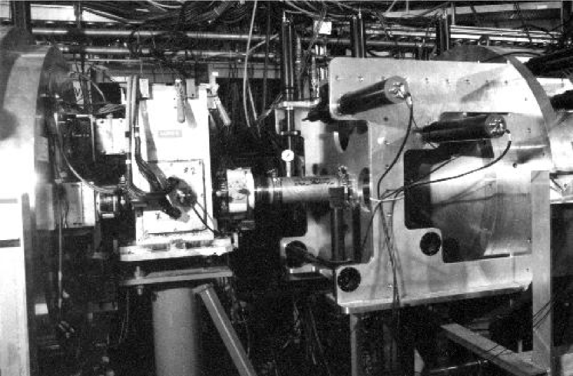
Two of these detectors are mounted in the experimental beamline to allow for extrapolation of the polarization profiles to the target location. They are shown in Figure 2. They are upstream of the Transverse field Ionization Chambers (TRIC’s) that sandwich the target. The TRIC signals (proportional to the beam current) determine the parity violating longitudinal analyzing power that is the observable of interest.
2.1 PPM Detectors
Each branch consists of a forward arm of two scintillators at
from the axis and a recoil arm. The angle of was chosen as
a reasonable compromise near the analyzing power maximum over the energy
range at which parity violation may be investigated at TRIUMF, see
Figure 3.
The figure of merit for a polarimeter can be defined as:
| (1) |
This is also shown in Figure 3.

The forward arm consists of two scintillators. The solid-angle of acceptance for scattered protons is defined by a rotated counter () whose angle of rotation along its axis perpendicular to the scattering plane is chosen to cancel the effect of the change in scattering cross-section and detector geometry with target blade position [21]. At 223 MeV, this rotation angle is determined to be with respect to the plane perpendicular to the nominal center-line of the scattered protons, in the direction as shown in Figure 4. Between the -counter and the target plane is a counter () whose function is to determine that the scattered protons are collinear with the target. The recoil arm is at at which the recoil protons from scattering will be stopped in the front () counter or in a 1.6 mm thick aluminum shield immediately behind it. Protons from other sources that are too penetrating will pass through and hit the veto () counter immediately behind. The location and dimensions of each counter are recorded in Table 1. A schematic of a single branch lay-out is given in Figure 4.
| Counter | Height | Width | Thickness | Distance | Arm |
|---|---|---|---|---|---|
| (mm) | (mm) | (mm) | (mm) | ||
| C | 37.5 | 37.5 | 6.4 | 600.2 | Forward |
| 28.5 | 46.0∗ | 6.4 | 900.0 | Forward | |
| R | 120.2 | 22.5 | 6.4 | 104.4 | Recoil |
| V | 156.9 | 30.0 | 6.4 | 151.7 | Recoil |
∗Counter is rotated at 49∘ with suitably beveled edges.

Each scintillator333BC-404; Bicron; 12345 Kinsman Rd., Newbury, OH, U.S.A., 44065 was attached to a light-pipe viewed by a two-inch RCA 8575444RCA Corp. photomultiplier tube. The TRIUMF-built bases were equipped with zener-diodes on the first three dynodes and the voltages had to be carefully adjusted due to the high rates. The front arm counters, and , of each branch were mounted externally with the protons passing through a 3.2 mm (at ) thick spun-aluminum shell, at a distance of 470 mm from the target, into air. The recoil arm counters, and , were mounted internally with a vacuum seal along each scintillator light pipe. The external counters and light pipes were wrapped with aluminized mylar and tape to keep out the ambient lighting; the internal counters were wrapped with a light-tight aluminum foil only and their external sections of light pipe were wrapped as the external counters.
2.2 PPM Targets
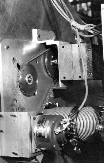
The mounting of the target blades and the drive arrangement is shown in Figure 5. The wheel pivots are 215 mm from the beam centre.
Each arm holds two targets to better balance the statistics of the PPM with the experiment statistics. This gives two scans and two scans per PPM, a total of eight. Each scan occurs during one spin-state of an eight state cycle. The direction of the spin in each state is defined by the eight state cycle which can be or its complement. The initial state of each cycle is chosen according to the same pattern, making up a 64-state ‘supercycle’. The initial spin direction of each supercycle is chosen randomly. This timing sequence is shown in Figure 7.
Each blade target is 1.6 mm wide, 5 mm along the beam, and 85 mm high (past its holder-clamp) and is machine cut from sheets of high density polyethylene. As each blade passes through the beam, a proton scattered in a plane containing the direction of motion of the blade is observed in one of the two forward arms, left-right (horizontal motion) or bottom-top (vertical motion), and the corresponding recoil proton from free scattering is observed in the recoil arm on the opposite side. Protons scattered in a plane perpendicular to the direction of motion of the blade (i.e., those that would give and ) are not recorded as their recoil protons would in many cases be stopped or severely multiple-scattered in the target.
The target blades are driven through the beam by a D.C. servo-motor/tachometer unit555Electro-Craft Corporation; 1600 Second St. So., Hopkins, MN, U.S.A. 55343 salvaged from an old reel-to-reel tape drive. The two wheels are connected by a timing belt that is mounted external to the PPM housing. This was done because it was proven necessary to ensure proper cooling. The power to the wheels is transmitted through ferrofluidically-sealed shafts666Ferrofluidics Corp.; 40 Simon St., Nashua, NH 03061, U.S.A.. The read-out of the shaft position was done through a shaft encoder777Type H25D; BEI Sensors and Motion Systems Co., Industrial Encoder Division; 7230 Hollister Ave., Goleta, CA, U.S.A. 93117-2891. It was found necessary to shield this encoder and switch to a rad-hard version as radiation damage caused failure after the first few weeks of running. This has not been a problem since.
In addition, with the blades turned off and parked out of the beam, it is possible to insert a fixed target of some 0.2 mm thick. This target has a very thin film of aluminum evaporated on the surface to prevent charging, and is mounted in a circular aluminum frame 100 mm in diameter. This allows a rapid determination of and in the parity beamline, useful for initial tuning of the solenoids that provide longitudinal polarization.
2.3 Synchronization and Control
The PPM’s rotate at five revolutions per second and are adjusted for angular mismatch. A full 200 ms cycle compromises eight blade passages with 25 ms between passages. The synchronization of the PPM’s, as well as the maintenance of the rotation speed, is accomplished by an application of electronic gearing. Each PPM is equipped with a 2500 line incremental shaft encoder and DC brushed servo motor.

The motors are controlled by a Galil DMC1030888Galil Motion Control, Inc.; 203 Ravendale Drive, Mountain View, CA, U.S.A. 94043-5216 3-axis PC ISA bus based digital servo motion control card. A functional block diagram of the control system is shown in Figure 6. A reference 60 Hz square wave signal is generated from the 60 Hz AC line which has a frequency regulation of 0.06%. This signal is frequency multiplied by a factor of 125 and phase locked to the 60 Hz line via a voltage controlled oscillator (VCO) feedback regulator circuit. The resulting 7500 Hz is phase shifted to produce a double phase quadrature signal. This is directed to the -axis encoder input of the DMC and represents the master axis signal which the slave axes, and , are commanded to follow through the gear function ratios, and . The phase slip function factor, , utilizes machine round off error which comes from the fact that 2500 is not evenly divisible by 60, so that at 5 Hz the right amount of phase slip relative to 60 Hz is obtained. This means that rotator speeds of 3 Hz, 6 Hz, 9 Hz, etc., can be set precisely to zero phase slip, while speeds in between cannot (unless the encoder resolution were changed to 3000 lines per turn). Normally, the phase slip is set to one 60 Hz cycle in 20 minutes. At 5 Hz, the encoder frequency is perfectly suited for this application. However, the factors , , and can be configured interactively by the user from the windows graphical user interface (GUI) at any time.
In normal operation the gearing is set for 1:1 on both PPM’s and the phase difference between the two PPM’s is set for . To compensate for small mechanical misalignment in the mechanisms, a fine phase adjustment is made so that the actual blade passages through the beam (between the two PPM’s) are exactly apart. The gear ratios and modify the output signal, from the -axis phase slip function and produces command frequency references, and , so the PPM speed is correctly calibrated, as required by the user, based on the 60 Hz line signal. During standard use , which means that the two PPM’s are phase locked to run at the same speed with zero relative phase slip.
Measurements with a digital oscilloscope showed that during rotation at 5 Hz the servo loops kept the two PPM’s within encoder tick (i.e, radians) of each other. The two reference signals, and , are treated by the microprocessor as quadrature counts which are the Basic Length Unit at machine hardware level. This means that the phase synchronization and position accuracy of the servo loop is four times greater than the line frequency of the encoder. These signals are compared in an up/down counter against the encoder feedback signal and the difference is used to produce an analog command voltage signal for the servo amplifier via a PID filter and DAC running at a sampling rate of 1 kHz. This produces the current to drive the motors. The PID filter parameters, , , and , are the same for both PPM’s due to their similar plant dynamics and shaft torque resistances. However, the stable operating region is very narrow due to the flexible couplings and the large inertia mis-match between the motor armature and the blade rotor mechanism (required due to space constraints). The aim is to increase in order to minimize the phase lock and position error, but not high enough to make the static gain loop unstable. To help stabilize the latter, is increased high enough to damp out the low frequency instabilities, but not high enough to destabilize the derivative loop gain. is set to zero in order not to induce low frequency oscillations into the loop due to the high load inertia. An interesting aspect to Figure 6 is that the distance between the PPM/Servo-Amp units at beam line level and the DMC controller is over 150 meters. This is very unusual in servo control applications due to the destabilizing effects of phase delay in the encoder and command signal cables; but was required due to the radiation environment.
For control measurements, it is possible to run a single PPM or to park a PPM’s blades at a specific angle.
3 Signal Processing and Data Acquisition
The PPM data collection is an integral part of the experimental data collection cycle. The PPM blade scans are carefully synchronized not only to each other, but are used to drive the polarized source spin flip cycle and the signal integration gates on the two transverse ion-chambers that bracket the target and whose helicity-dependent output constitutes the parity-violating signal of the experiment. Each shaft encoder pulse forms the time-base for the experiment as an input to a timing and sequence module999Model 221; Jorway Corp.; 27 Bond St., Westbury, NY, U.S.A. 11590. A schematic diagram of the data collection cycle is shown in Figure 7.

3.1 Electronics
A schematic lay-out of the PPM electronics is given in Figure 8.

The signals from the phototube bases were fed through an amplifier, thus allowing the tubes to be run at lower voltages, important due to the high singles rates, and into individual linear discriminators. Each pair of forward arm signals, and , were formed into a logical coincidence, , and each recoil arm was formed into an anticoincidence, . These were timed together to form and (del indicating that the signal has been delayed by one cyclotron RF period — 43 ns), where the first is the coincident signals, , , , and , and the latter are their corresponding accidentals, , , , and . These signals are grouped together in common modules for and and for the two PPMs, which can be inhibited by the timing sequence. This allows a fan-in of the signals, for example , , , and , together and they are then presented to the same scaler input, as their respective blades are never in the beam at the same time.
The scanning scalers and memory modules1010103521A, MM8206A; LeCroy Research Systems; 700 Chestnut Ridge Road, Chestnut Ridge, NY, U.S.A. 10977-6499 read in the data in synch with a clock signal. As each blade moves through the beam the scaler advances through a sequence of channels that are related to the position of the blade. The data is then read out through a routine running in a dedicated processor111111Starburst J11; Creative Electronic Systems; 70 route de Pont Butin, 1213 Petit-Lancy 1, Switzerland that stores the results in memory according to the timing sequence, e.g., , , , and , and the spin-state. Thus there is a requirement for only four such scalers and memory modules to record two true and two accidental signals per blade. This allows many of the more crucial experimental modules to reside in a single crate, important for the in-crate control through the Starburst and timing sequences. The status of each spin state ( or helicity) is nowhere introduced as a gating signal to any of the hardware; thus avoiding undesirable cross-talk which might lead to a helicity-dependent electronics effect. Rather, the spin state status of the initial state (state 1, see Fig. 7) in a pattern of eight states is separately reported, as a frequency modulated/encrypted signal, to the computer.
3.2 Data Acquisition
The PPM information was read out of the front-end processor as a separate event, there being separate events for the TRIC and other monitor information. This allowed the PPM information to be transferred to the main data acquisition computer121212VAXstation 3200; Digital Equipment Corp.; Maynard, MA, U.S.A. while other data was being collected, and vice versa. The data was then written to tape and made available to other processors for on-line analysis and monitoring. The last was especially important for the PPM data as it allowed us to monitor both transverse polarization components and the first moments of polarization on a run-by-run (approximately hourly) basis. If these observables became excessively large, then the beam-line solenoids or other cyclotron parameters were tuned to reduce them. As PPM information was available in each data buffer, each buffer (200 ms of data) could be analyzed separately and bundled as seemed appropriate for a regression analysis. A first analysis of such a kind was done in a semi-online manner so that more sophisticated monitoring of the experiment could be carried out.
4 Results
The PPM counter’s were run at a comparatively high rate. Table 2 shows the peak rates for both singles in each individual counter and the coincidence rate at a beam current of 200 nA and a size of 5 mm. At this current, first order accidentals (forward arm accidentally in coincidence with the recoils arm) were typically 35% of the coincidence rate.
Two higher order accidentals were examined: (1) with an accidental hit in the counter; and (2) with an accidental hit in the counter. The first are ‘near’ events in the sense that they are close to the acceptance of the PPM with a similar (very slightly lower, see Fig. 3) analyzing power; and the second are ‘stolen’ events in that they would have been accepted as true events but for the accidental veto. Both might result in errors in the measured intrinsic first moment of polarization coupled to a helicity correlated change in the beam intensity (otherwise, they just tend to pull down the average analyzing power slightly). The effects were measured by taking data with a 43 ns (one RF period for the TRIUMF cyclotron) delay in the counter for case (1), and a 43 ns delay in the counter for case (2). For an assumed helicity dependent variation of current, , the change in the first moment due to case (1) was , and for case (2) was . As these would result in false terms to of the order of , they were inconsequential for the experiment.
| Detector | Peak Singles Rate (MHz) |
|---|---|
| C | 3.1 |
| 0.8 | |
| R | 3.0 |
| V | 1.5 |
| Coincidence | Peak Rate (kHz) |
| 110. | |
| 38. |
Tests were also done with carbon blades replacing the usual blades in the polarimeter. These indicated that 1% of the true events in the PPM came from the carbon in the blades (, etc.). This had a very small contribution to the effective analyzing power.
As the data collection involved spin off periods interspersed with the polarized beam, it was possible to monitor the PPM’s response (instrumental asymmetry) to zero polarization (ideally what we would like to see in the experiment with a perfect longitudinally polarized beam). An instrumental asymmetry as a function of blade position plot is presented in Figure 9.

It was found that the slope of the instrumental asymmetry was strongly dependent on the divergence or convergence of the beam, as then the angle of incidence is position dependent and the scattering angle dependence on position is different from the assumption of a parallel beam. Note that the requirement for the experiment is for as parallel a beam (i.e., very weakly focussed at the target) as reasonably achievable.
Figure 10 shows a helicity-correlated polarization profile measured by the upstream PPM with 200 nA beam and a beam size () of 5.0 mm.

Under those conditions, each PPM measures an average and to 0.002 and and to 7 m in one hour.
The effective analyzing power as a function of blade position is determined by moving the beam across the range of the blade sweep with the beam transversely polarized. Absolute calibration was done by comparing the integrated result to the existing IBP.
5 Conclusions
The PPM rotation control system has worked very well. It is convenient to use and normally maintains PPM synchronization to one shaft encoder line.
The PPM’s have been successfully used throughout the TRIUMF Parity experiment (E497). For three runs (not the full data set) of data taken in 1997, 1998 and 1999 (about four months) consisting of about 240 hours of TRIC data (the actual parity violation measurement) collection: The ‘false’ parity violating analyzing power () derived from transverse components of polarization coupled with a displacement from the ideal instrumental symmetry axis has been measured as . The false derived from the first moments of polarization has been measured as . This confirms the expectation that the latter is a large (indeed, so far, the largest) correction. It is also the largest contribution to the E497 error. Improved PPM error to total error could be achieved by changing the number of targets (and thus the ratio of PPM data collection time to TRIC data collection time) or seeking some other means of rapidly and accurately measuring the polarization profiles.
References
-
[1]
S. Kistryn et al., Phys. Rev. Lett. 58,
(1987) 1616.
-
[2]
R. Balzer et al., Phys. Rev. C 30,
(1984) 1409.
-
[3]
P.D. Eversheim et al., Phys. Lett. B 256,
(1991) 11.
-
[4]
V. Yuan, H. Frauenfelder, R.W. Harper, J.D. Bowman,
R. Carlini, D.W. MacArthur, R.E. Mischke, D.E. Nagle, R.L. Talaga,
and A.B. McDonald, Phys. Rev. Lett. 57, (1986) 1680.
-
[5]
J.M. Potter, J.D. Bowman, C.F. Hwang, J.L. McKibben,
R.E. Mischke, D.E. Nagle, P.G. Debrunner, H. Frauenfelder, and
L.B. Sorensen, Phys. Rev. Lett. 33, (1974) 1307.
-
[6]
A.R. Berdoz et al., in Proc. of the Int’l. Conf.
on Quark Lepton Nuclear Physics (QULEN‘97), H. Ejiri, T. Kishimoto,
Y. Mizuno, T. Nakano, and H. Toki, eds., Nucl. Phys. A629, (1998) 433c;
S.A. Page et al., in Proc. of the Int’l. Symposium on Weak and
Electromagnetic Interactions in Nuclei (WEIN-89), edited by P. Depommier,
Editions Frontieres (1989) 557.
-
[7]
R.W. Harper, V. Yuan, H. Frauenfelder, J.D. Bowman,
R. Carlini, R.E. Mischke, D.E. Nagle, R.L. Talaga, and A.B. McDonald,
Phys. Rev. D 31, (1985) 1151.
-
[8]
J.D. Bowman et al., Phys. Rev. Lett. 34,
(1975) 1184.
-
[9]
J. Birchall et al., in Polarization Phenomena
in Nuclear Physics, AIP Conf. Proc. 339, (1995) 136.
-
[10]
J. Birchall et al., TRIUMF Experiment proposal
E761, (1995) unpublished.
-
[11]
M. Simonius, Phys. Lett. 41B, (1972) 415.
-
[12]
M. Simonius, R. Henneck, Ch. Jacquemart, J. Lang,
W. Haeberli, and Ch. Weddigen, Nucl. Instr. and Meth. 177, (1980)
471.
-
[13]
D.E. Nagle, J.D. Bowman, C. Hoffman, J. McKibben,
R. Mischke, J.M. Potter, H. Frauenfelder, and L. Sorenson, in High
Energy Physics with Polarized Beams and Targets, ed. by G.H. Thomas,
AIP Conf. Proc. 51, (1978) 224.
-
[14]
W. Haeberli, R. Henneck, Ch. Jacquemart, J. Lang,
R. Müller, M. Simonius, W. Reichart, and Ch. Weddigen, Nucl.
Instr. and Meth. 163, (1979) 403.
-
[15]
J. Chlebek, S. Kuhn, P.D. Eversheim, and F. Hinterberger,
Nucl. Instr. and Meth. in Phys. Res. A256, (1987) 98.
-
[16]
B. Vuaridel, K. Elsener, W. Grüebler, V. König,
and P.A. Schmelzbach, Nucl. Instr. and Meth. in Phys. Res. A244,
(1986) 335.
-
[17]
J. Birchall, Can. J. Phys. 66, (1988) 530.
-
[18]
R.A. Arndt, Interactive dial-in program SAID, 1994;
R.A. Arndt, I.I. Strakovsky, and R.L. Workman, Phys. Rev. C 50,
2731 (1994).
-
[19]
J. Soukup et al., Beam Instrumentation Workshop,
AIP Conf. Proc. 333, (1994) 492.
-
[20]
A.R. Berdoz et al., Nucl. Instr. and Meth. A307, (1991)
26.
-
[21]
L.G. Greeniaus and J. Soukup, TRIUMF Report No.
TR-DN-81-1, (1987) unpublished.