LARGE-SCALE SIMULATION OF BEAM DYNAMICS IN HIGH INTENSITY ION LINACS USING PARALLEL SUPERCOMPUTERS††thanks: Work supported by the DOE Grand Challenge in Computational Accelerator Physics, Advanced Computing for 21st Century Accelerator Science and Technology Project, and the Los Alamos Accelerator Code Group using resources at the Advanced Computing Laboratory and the National Energy Research Scientific Computing Center.
Abstract
In this paper we present results of using parallel supercomputers to simulate beam dynamics in next-generation high intensity ion linacs. Our approach uses a three-dimensional space charge calculation with six types of boundary conditions. The simulations use a hybrid approach involving transfer maps to treat externally applied fields (including rf cavities) and parallel particle-in-cell techniques to treat the space-charge fields. The large-scale simulation results presented here represent a three order of magnitude improvement in simulation capability, in terms of problem size and speed of execution, compared with typical two-dimensional serial simulations. Specific examples will be presented, including simulation of the spallation neutron source (SNS) linac and the Low Energy Demonstrator Accelerator (LEDA) beam halo experiment.
1 INTRODUCTION
The high intensity of future accelerator-driven systems places stringent requirements on the allowed beam loss, since very small fractional losses at high energy can produce unacceptably high levels of radioactivity. Previous studies suggest that the low density, large amplitude halo of the beam is a major issue for these systems [1, 2, 3]. Large-scale simulations are an important tool for exploring the beam dynamics, predicting the beam halo, and facilitating design decisions aimed at controlling particle loss and meeting operational requirements.
The most widely used model for simulating intense beams in ion rf linacs is represented by the Poisson-Vlasov equations. These equations are often solved using a particle-in-cell (PIC) approach. In this paper we will describe a parallel simulation capability that combines the PIC method with techniques from magnetic optics, and we will present results of using parallel supercomputers to simulate beam dynamics in high intensity ion rf linacs.
2 PHYSICAL MODEL AND NUMERICAL METHODS
In the PIC approach a number of simulation particles, called macroparticles, are used to solve (indirectly) the evolution equations and model the charged particle dynamics. The motion of individual particles in the absence of radiation can be described by Hamilton’s equations,
| (1) |
where denotes the Hamiltonian of the system, and where and denote canonical coordinates and momenta, respectively. In the language of mappings we would say that there is a (generally nonlinear) map, , corresponding to the Hamiltonian , which maps initial phase space variables, , into final variables, , and we write
| (2) |
The potential in the Hamiltonian includes contributions from both the external fields and the space-charge fields. In the Poisson-Vlasov approach, discreteness effects are neglected and the space charge is represented by a smoothly varying mean field. Typically, the Hamiltonian can be written as a sum of two parts, , which correspond to the external and space-charge contributions. Such a situation is ideally suited to multi-map symplectic split-operator methods [4]. A second-order-accurate algorithm for a single step is given by
| (3) |
where denotes the step size, is the map corresponding to and is the map corresponding to . This approach can be easily generalized to higher order accuracy using Yoshida’s scheme if desired [5].
The electrostatic scalar potential generated by the charged particles is obtained by solving Poisson’s equation
| (4) |
where is the charge density. We have developed a Fourier-based transformation and an eigenfunction expansion method to handle six different boundary conditions: (1) open in all three dimensions; (2) open transversely and periodic longitudinally; (3,4) round conducting pipe transversely and open or periodic longitudinally; (5,6) rectangular conducting pipe transversely and open or periodic longitudinally. A discussion of the numerical algorithms for solving the Poisson’s equation with these different boundary conditions can be found in [8].
The charge density on the grid is obtained by using a volume-weighted linear interpolation scheme[6, 7]. After the potential and electric field is found on the grid, the same scheme is used to interpolate the field at the particle locations. During the course of the simulation each step involves the following: transport of a numerical distribution of particles through a half step based on , solving Poisson’s equation based on the particle positions and performing a space-charge “kick” , and performing transport through the remaining half of the step based on .
3 APPLICATIONS
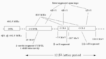
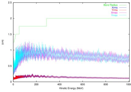
We have applied the above 3D parallel PIC approach to an early design of the SNS linac and to the proposed LEDA beam halo experiment. Our simulation of the SNS linac starts at the beginning of the DTL. The code advances particles through drift spaces, quadrupole fields and RF gaps. The dynamics inside the gaps is computed using external fields calculated from the electromagnetic code SUPERFISH [9]. A schematic plot of the SNS linac configuration used in this study is shown in Figure 1 [10]. It consists of three types of RF structures: a DTL, a CCDTL, and a CCL. There are a total of 425 RF segments in the linac. Figure 2 shows the rms transverse size () and the maximum transverse extent () of the bunched beam in the linac with one set of errors. We see that the maximum particle amplitude is well-below the aperture size of the linac. This margin is needed to operate the linac safely and to avoid beam loss at the high energy end. The jump in rms beam size between the DTL and CCDTL at MeV is due to a change of focusing period from to at MHz.
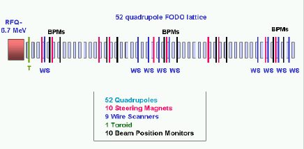
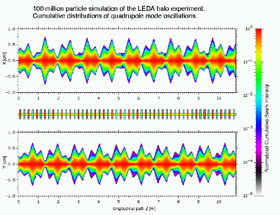
In the LEDA beam halo experiment, a mismatched high-intensity proton beam will be propagated through a periodic focusing transport system and measurements will be made of the beam profile. The goals of the experiment are two-fold: first, to study beam halo formation and test our physical understanding of the phenomena, and second, to evaluate our computational models and assess their predictive capability through a comparison of simulation and experiment. Fig. 3 gives a schematic plot of the layout of the experiment [11]. It consists of 52 alternating-focusing quadrupole magnets with a focusing period of cm. The gradients of the first four quadrupole magnets can be adjusted to create a mismatch that excites the breathing mode or the quadrupole mode. The transverse beam profile will be measured using a beam-profile scanner. Fig. 4 and Fig. 5 present simulation results of the transverse beam size for the breathing mode and the quadrupole mode, plotted at the center of the drift spaces between quadrupole magnets, as a function of distance. The plots include both the rms beam size and the maximum particle extent in the simulation. The physical parameters for the simulation were I= mA, E=6 MeV, and f= MHz. The simulation was performed using million macroparticles with a 128x128x256 (x-y-z) space-charge grid.


From Fig. 4, the two transverse components of the breathing mode are in phase, while the quadrupole mode in Fig. 5 has the two components out of phase. Evidently, it will be possible in the experiment to clearly excite either of the two modes. Furthermore, the debunching of the beam will not significanly alter the structure of the oscillations. Fig. 6 shows the accumulated one-dimensional density profiles (along ) for the breathing mode and the quadrupole mode just after the magnet #.

The breathing mode is more peaked and has a larger extent than the quadrupole mode. Measurements will be taken at this location and will be compared with our simulations. The data in Fig. 6 are well-resolved over a range of about decades.
An important piece of information from a design standpoint is amount of charge beyond a specified radius or spatial location as a function of distance along the accelerator. This is shown graphically in Fig. 7 which shows the complement of the horizontal and vertical cumulative density profiles, at every step, when the quadrupole mode is excited. In other words, the contours describe the fraction of charge that would be intercepted by a scraper placed at that transverse position.
The above LEDA simulations used 100 million macroparticles and a 3D Poisson solver, and required only 2 hours to execute on 256 processors. In contrast, beam dynamics simulations performed on serial computers typically use 10,000 to 100,000 macroparticles and a 2D Poisson solver. Even if the above large-scale calculations could be performed on a PC, they would require on the order of a month to complete. In conclusion, while small-scale simulations on serial computers are extremely valuable for rapid design and predicting rms properties, large-scale simulations are needed for high-resolution studies aimed at making quantitative predictions of the beam halo.
4 Acknowledgments
We thank the SNS linac design team and the LEDA beam halo experiment team for helpful discussions. We also thank S. Habib for helpful discussions and C. Thomas Mottershead for graphics support.
References
- [1] R. L. Gluckstern, Phys. Rev. Lett. 73, 1247 (1994).
- [2] T. P. Wangler, K. R. Crandall, R. Ryne, and T. S. Wang, Phys. Rev. ST Accel. Beams 1, 084201 (1998).
- [3] J. Qiang and R. D. Ryne, Phys. Rev. ST. Accel. Beams 3, 064201 (2000).
- [4] E. Forest et al., Phys. Lett. A 158, 99 (1991).
- [5] H. Yoshida, Phys. Lett. A 150, 262 (1990).
- [6] R. W. Hockney and J. W. Eastwood, Computer Simulation Using Particles, Adam Hilger, New York, 1988.
- [7] C. K. Birdsall and A. B. Langdon, Plasma Physics Via Computer Simulation, McGraw-Hill Book Company, NY, 1985.
- [8] J. Qiang and R. Ryne, ”High Performance Particle-In-Cell Simulation in a Proton Linac,” to be submitted to PRST-AB.
- [9] J. H. Billen and L. M. Young, ”POISSON SUPERFISH”, LANL Report LA-UR-96-1834 (revised Jan. 8, 2000).
- [10] T. Bhatia et al., ”Beam Dynamics Design for the 1-GeV 2-MW SNS Linac,” LANL Report LA-UR-99-3802, 1999.
- [11] T. Wangler, ”LEDA Beam Halo Experiment-Physics and Concept of the experiment,” LA-UR-00-3181, 2000.