Formation of Structure in Snowfields:
Penitentes, Suncups, and Dirt Cones
Abstract
Penitentes and suncups are structures formed as snow melts, typically high in the mountains. When the snow is dirty, dirt cones and other structures can form instead. Building on previous field observations and experiments, this work presents a theory of ablation morphologies, and the role of surface dirt in determining the structures formed. The glaciological literature indicates that sunlight, heating from air, and dirt all play a role in the formation of structure on an ablating snow surface. The present work formulates a mathematical model for the formation of ablation morphologies as a function of measurable parameters. The dependence of ablation morphologies on weather conditions and initial dirt thickness are studied, focusing on the initial growth of perturbations away from a flat surface. We derive a single-parameter expression for the melting rate as a function of dirt thickness, which agrees well with a set of measurements by Driedger. An interesting result is the prediction of a dirt-induced travelling instability for a range of parameters.
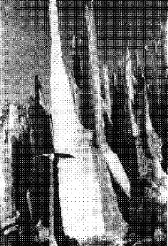
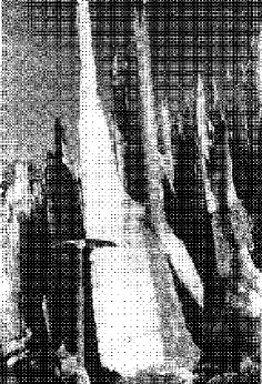
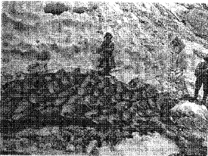
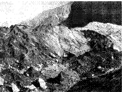
Penitentes are structures of snow or ice [1], which commonly form during the summer on glaciers or snow fields at high altitudes (in the Andes and Himalaya). A penitente is a column of snow, wider at the base and narrowing to a point at the tip. The name “penitente” is a Spanish word meaning “penitent one,” and arose because a field of penitentes resembles a procession of monks in white robes. Penitentes range from one to six meters high with the spacing between columns comparable to their height (Figure 1). Smaller structures, known as suncups or ablation hollows, can be found in lower mountains like the Rockies and the Alps (Figure 2). Suncups are smaller, two cm to half a meter in size.
The first written record of penitentes comes from Charles Darwin, who observed them during his travels in the mountains of Chile [3].
“Bold conical hills of red granite rose on each hand; in the valleys there were several broad fields of perpetual snow. These frozen masses, during the process of thawing, had in some parts been converted into pinnacles or columns, which, as they were high and close together, made it difficult for the cargo mules to pass. On one of these columns of ice, a frozen horse was sticking as on a pedestal, but with its hind legs straight up in the air. The animal, I suppose, must have fallen with its head downward into a hole, when the snow was continuous, and afterwards the surrounding parts must have been removed by the thaw.”
An extensive literature of observations and field experiments has documented these ablation morphologies (see [2] for many references). Ablation in this context means removal of snow by melting or sublimation. This contrasts with other processes like wind, avalanches, and rain. There is a consensus about the causes of ablation morphologies, although some contradictory claims do exist in the literature. For penitentes, bright sunlight and cold, dry weather are apparently required [2], while ablation hollows can be formed in three distinct ways, with solar illumination important in some settings. For other locations, uniform heating from the air appears to be the key effect. The effect of this “sensible” heat transfer (so called because it is easily felt with the senses) to the snow depends on whether the snow is clean or dirty. Since many readers are likely to be unfamiliar with the glaciological literature, I give a brief review here.
The observational evidence for sunlight-driven formation of penitentes is abundant. In early work, Matthes[4] argued that a variety of ablation forms, from sun cups a few inches in size to penitentes many feet deep, are formed by the sun. As he pointed out, the formation of the largest penitentes requires strong and prolonged solar radiation—the primary reason why penitentes develop only in regions with dry summer climates. Matthes also observed that penitentes tilt toward the elevation of the midday sun (an observation confirmed by others [1, 5, 6, 7, 8]). Such tilting is strong evidence that the sun has an important role in the development of structure, because the direction of incident radiation provides the symmetry axis in the problem. In later work, Lliboutry [8] observed that incipient penitentes begin as east-west rows. Perhaps most important, if the weather is not dominated by direct sunlight—if the weather is cloudy[4] or very windy[4, 8]—penitentes are observed to decay. In the 1930s Troll performed an experiment trying to create penitentes[7]. The exact statement (reported by Lliboutry[8]) is “Troll was able to reproduce penitents in Germany by shining an electric bulb on fresh snow during a cold, dry night.” This supports the sunlight mechanism, although to my knowledge no controlled laboratory experiments have investigated light-driven structure formation.
To understand qualitatively how sunlight can cause structure formation, note that when light is reflected off the snow, the base of a depression receives more reflected light than the neighboring peaks. This drives an instability of the surface and the amplitude of a perturbation grows; quantifying this argument will be a main goal of this paper. The effects of reflections are considered imporant by several observers [4, 8, 9]. This may not be the only required effect. At the high altitudes where penitentes commonly form, the air is so cold and dry that sublimation occurs instead of melting [10], consistent with the observations that the snow in penitentes is quite dry [4, 8]. Lliboutry [8] claims that the snow in the hollows between penitentes is soft and wet, and that temperature variations of 5-10∘ C exist between the peaks and the troughs. This was interpreted to indicate snow sublimating from the peaks and melting near the troughs—an effect which accelerates the growth of structure, since 7 times more heat is required to sublimate a volume of snow than to melt it. Lliboutry believes this effect to be crucial for the development of the largest structures, and claims that penitentes only appear at altitudes high enough that sublimation becomes important. But other researches report results in disagreement with this [4, 6].
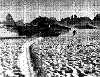
A different set of observations and experiments have led to a very different claim: that solar illumination destroys ablation morphologies, while windy weather promotes their growth. Leighly[11] argued that heat from air (delivered by wind) leads to the formation of ablation polygons (cf. Figure 3). Others state [12, 13, 14] that structures do not grow in the presence of direct sunlight. Ashwell and Hannell claim[15] that when the incident solar power is larger than the incident power from heating by wind the hollows decay. Detailed observations, along with wind-tunnel experiments, have been made by Takahashi and collaborators[16, 17]; they conclude that structures grow most rapidly when the air temperature and wind speed are highest[18]. When the weather is warm and cloudy, wind mixes the air so heat is delivered at a steady rate to the surface; the higher the temperature and wind speed, the faster the heating.
Rhodes, Armstrong, and Warren [2] suggested a resolution to this apparent contradiction, which I now summarize. In their view, dirt on the snow surface is the hidden variable distinguishing the two cases. Sunlight drives formation of penitentes in clean snow because reflection into hollows makes depressions in the snow surface grow. Any source of ablation which transfers heat uniformly to the snow surface therefore disrupts formation of structure. However, sunlight acts differently on a dirty snow surface. Dirt decreases the amount of reflected light, preventing the concentration of sunlight in the hollows. This agrees with the Rhodes et. al. observations of suncups on Mount Olympus. The researchers noticed that when the snow surface was covered by a layer of ash from the eruption of Mount Saint Helens, suncups did not form. They scraped away the ash from one patch of snow and observed the formation of sun cups on this clean snow surface.
How does dirt affect snow ablation? If the dirt thickness covering the snow is sufficiently thick, the dirt forms an insulating layer which slows down the ablation rate of the snow [20]. Thus dirt can have different effects, depending on thickness. A thin layer of dirt causes faster ablation because reflection is inhibited. However, sufficiently thick dirt slows ablation. A large amount of work has looked at how debris-covered ice or snow melts [10, 15, 21]; one typically finds a peak in the ablation rate for dirt thickness around 0.5–5 cm. One nice experiment was done by Driedger[22], who measured ablation rate as a function of ash thickness on the South Cascade Glacier (primarily due to melting). The typical grain sizes of the ash were 0.25 to 1.0 mm diameter, and the maximum ablation rate occurred for a dirt thickness of 3 mm. The data from her measurements are shown in Figure 6. Comparison to these data provides a test of my model, as discussed below.
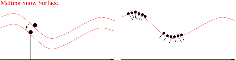
As pointed out by Ball[23], small particles of dirt adhere to the snow surface. This is true only for sufficiently small dirt particles: the adhesive force on the particle must be large compared to the gravitational force[15]. When adhesion to the snow dominates, the pieces of dirt move perpendicular to the snow surface (rather than falling straight down) as the snow ablates. Sticky dirt therefore tends to become concentrated on the most elevated regions of the surface. (See Figure 4.) The concentration of dirt on melting snow can be observed in old snow piles in cities, and is illustrated in Figure 3. This movement of dirt normal to the melting snow surface is quantitatively well-documented in the literature (summarized in [2]). For the arguments here to be correct qualitatively, the dirt need not move completely normal to the surface—a component of motion normal to the surface is adequate.
This mechanism explains dirt-driven structure formation: as the snow ablates, dirt becomes concentrated on the more elevated parts of the surface. The thicker dirt forms an insulating layer on the ridges, so they ablate more slowly. The hollows thus grow deeper. This concentration of dirt by ablation can, in extreme cases, lead to the formation of so-called dirt cones: cones of snow or ice covered by a thick layer of dirt[10, 20, 21, 24]. (See Figure 3.) These structures can become quite large: Swithinbank [24] reports a dirt cone in the Himalaya estimated to be 85 m high! Drewry [21] has done detailed experiments on dirt cones. He concludes that the cones ultimately reach a steady state, where the motion of dirt toward the center of the cones is balanced by the debris sliding down the cone when the slope angle is too large.
The proposal of Rhodes, Armstrong, and Warren [2] that uniform heating causes structure only for dirty snow does not completely resolve the disagreement about structure formation. Some observers who advocate uniform-heating driven formation of ablation hollows insist that dirt on the snow surface is not required [11, 13, 16, 17]. Indeed, some photographs show ablation hollows in clean snow inside a tunnel or on other inverted surfaces, suggesting that neither dirt nor solar illumination are necessary. How can this be explained? Some have suggested that a regular pattern of convection cells leads to the observed polygonal pattern[11, 12], but a simple estimate shows this cannot give the correct size structures [25]. Another suggestion is that the structures are formed by turbulent eddies[13, 16], although Takahashi [17] later claimed that the diameters of the hollows are independent of the eddy size. Takahashi [17] proposed that the separation of the air boundaray layer as it flows over a cusp could produce lower temperatures at the cusp, and therefore lead to structure formation. I am not familiar with any further theoretical or experimental consideration of the Takahashi proposal; this mechanism for structure formation will not be considered in this paper.
Despite the extensive observations of ablation morphologies, there is a lack of mathematical models of their growth [26]. The goal of this paper is to quantify the primary mechanisms discussed above, and characterize the initial stages of the instability of a flat surface. We examine how reflection of sunlight and dirt affect structure formation. The nonlinear evolution more appropriate to penitentes will be examined in a future paper.
In this paper we consider sunlight—direct and reflected—the primary source of heat which leads to snow ablation. It is well-documented that radiation is the dominant heat source for ablating snow [27, 28], especially at high altitudes and low latitudes [6]. The importance of considering reflected light as well as direct illumination is supported by the observational evidence. The fraction of light reflected from old snow is about 0.5 [10, 27]. Therefore the amount of heat absorbed locally (and correspondingly the ablation rate) can vary by up to a factor of two for different parts of the surface—such a large variation can have important consequences for structure formation. Kotlyakov and Lebedeva [6] made measurements of the albedo on a glacier with small penitentes. In a measurement averaged over surface features, ten percent more light was absorbed when the sun was high overhead, presumably indicating the absorption of reflected light in the structures.
In the presence of dirt, sensible heating from the air may be important, in addition to sunlight. In this paper I focus primarily on the sunlight-dominated case, and comment on similarities and differences with sensible heat. Modifying the model to include sensible heating is straightforward.
By forming a quantitative model, we can test whether the effects considered can explain the appearance of structure, and describe the morphologies produced. The primary goal is to formulate the simplest model which contains the essential physics. Ideally the theory would contain no free parameters, that is, all parameters in the model can be calculated or measured in experiments. We also discuss which effects are left out of the simple model, and estimate how serious are the consequences for such omissions.
The first part of this paper addresses clean snow only. In section I we formulate a minimal model, and carry out the analysis of the model for small perturbations. The linear stability analysis lets us estimate the wavelength of the fastest-growing disturbance, and determines the initial size structures that form. This analysis allows us to make testable predictions of the conditions necessary to observe structure.
We then discuss the effect of dirt and re-formulate the model to include dirt in section II. We compare our model to the field experiment of Driedger and find good agreement. Thus reassured that the theory contains the imporant physical effects, we show how dirt alters the growth of small perturbations. We show that a thin dirt layer suppresses the reflection-driven instability and induces travelling dispersive waves on the surface. In the limit of thick dirt, we demonstrate the insulation-driven instability expected from the discussion above.
I Light Reflection on Clean Snow
The model for penitente growth we derive here contains simplifying assumptions; we hope to capture the essential features while neglecting some effects We will discuss the assumptions and their limits of validity as the model is developed. Some of the most important simplifications include considering the latent heat to be constant and including only first-order, isotropic reflections. We focus on a one-dimensional model of penitentes, assuming invariance in the transverse direction, although it is straightforward to generalize these equations to two dimensions or to multiple reflections.
We consider the height of the snow surface , and seek an equation for the time evolution of .
A Snow Ablation
Heat incident on the surface leads to ablation—the height decreases as the snow melts or sublimates. We assume that ablated snow vanishes into the air or drains, and therefore that the flow of water along the surface and re-freezing are not important (and similarly that other changes in the nature of the snow are unimportant). This model can apply to either melting or sublimation. We use the term “ablation” to refer to removal of snow in either way.
Suppose a point on the surface absorbs a power per unit horizontal area . The latent heat required to ablate a unit volume of snow is . Combining this with an effective diffusive smoothing term (see below) gives the evolution equation for the surface:
| (1) |
For clean snow, we assume that is a constant (independent of ). This is true when the surface temperature and humidity are approximately constant. As discussed in the introduction, fully developed penitentes may have melting in the hollows and sublimation in the tips—a situation which requires to vary along the surface. Indeed, the variation in might be the essential effect for large structures. For small angle structures, that is, amplitude small relative to wavelength, constant should be a good approximation. Later, we will include spatial variation in the effective due to dirt on the snow surface—see section II.
The second term in equation 1 for the surface height is a simple form of the small-scale cutoff: a diffusive term with diffusion constant . As we will see below, in the absence of any smoothing term, the model can produce arbitrarily small structures. This is clearly not realistic, because the physics at small scales will cut off the instability. For the qualitative results here, the exact mechanism of the small-scale cutoff is not essential; the main point is that there is some minimum size structure which can form. A natural small-scale cutoff is the extinction length of sunlight, which defines the thickness of the snow layer in which the light scattering takes place[27]. Points on the snow surface within one extinction length are not optically independent, and therefore such nearby points ablate at the same rate. The extinction length depends on the density and grain structure of the snow. The typical extinction length[27, 28] for old snow (grain radius 1 mm) is of order 1 cm[29]. We will choose the diffusion coefficient so that the characteristic cutoff length is of order the optical extinction length. Again, remember that this term in the height equation is a simplified representation of the small-scale physics, and any conclusions which depend sensitively on the form of this term should be considered suspect. Note that diffusion of heat through the snow might seem another natural form of the small-scale cutoff; however the gradients of temperature in the snow are not large enough for thermal diffusion to stabilize short wavelengths[30].
We note here that recent work by Nodwell and Tiedje [25] considers the scattering of light in the snowpack in quantitative detail. They find a range of length scales where suncups can form (both a minimum and maximum wavelength), a result which our simplified model cannot produce.
B Light Reflection
In this section we describe the reflection of sunlight from the snow surface. We assume that the sunlight shines directly down (in the direction) and has a uniform power per unit length . The parameter characterizing reflections is the albedo , which denotes the fraction of light reflected. Thus the absorbed power per unit length is . For old snow—called firn—a typical value is [10].
The reflecting properties of snow are different from those of a mirror. Snow looks white because it scatters light in many directions, as we would expect for a rough surface. Here we treat the light using ray optics, and assume the surface reflects isotropically, thus the power is distributed uniformly into of solid angle outside the surface. We approximate that the reflection occurs at the surface of the snow. (As mentioned above, the reflection takes place in a layer of order 1 cm thick. We ignore this in formulating the reflections, and include its effects schematically through the diffusive term.)
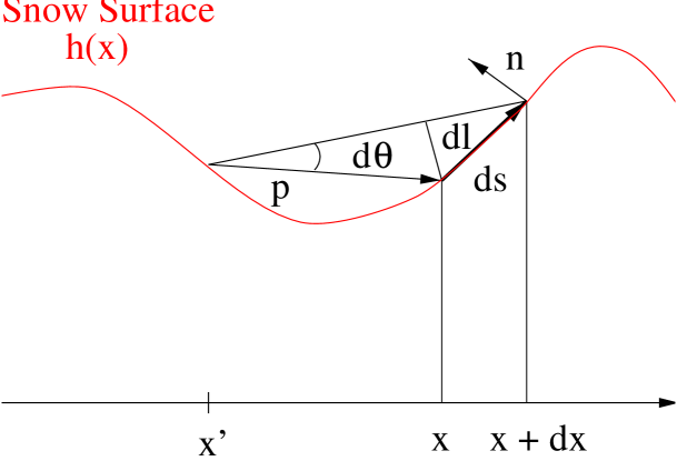
Using these properties, the total amount of light scattered from an interval around point to the interval between and is
| (2) |
where is the angle subtended by the surface between and (see Figure 5).
We can find in terms of the shape of the surface.
where we have used and
| (3) | |||||
| (4) |
and is the vector tangent to the surface
| (5) |
We define the vector , which points from the point to the point . From Figure 5, we can see that
| (6) |
To find the total power reflected to point , we must add up the intensity scattered from all points :
| (7) |
The integrand in this equation is the propagator for light intensity, it describes how the intensity is carried from one point to another on the surface; is the intensity due to a single reflection. To include multiple reflections, we can write the power as an integral equation for .
| (8) |
This can be written as a power series in . We will only consider single reflections here, which does not introduce a large error when is small. For old snow, a typical value of . Including the higher-order correction from multiple reflections may be important in determining the precise details of the largest shapes.
This formula for reflected intensity is not complete, because it neglects the line-of-sight constraint. Light cannot scatter from to if the path of the light ray is blocked by another part of the surface. This requirement is a nonlinear constraint which is difficult to handle analytically but is straighforward to implement in numerics. We typically indicate the constraint schematically, by writing “line of sight” under the integral:
We can also write a necessary (but not sufficient) criterion for the line of sight constraint, when applied to local analysis within one “basin.” The two points and are within line of sight of each other when the dot product of the vector normal to the surface and the vector is less than 0: . (See Figure 5.) Note, however, that this simple criterion will miss intermediate bumps in the surface. In other words, the constraint may be satisfied but no reflection occurs between and because the line of sight is blocked by an intervening peak.
C Model
The equations combining reflection and ablation are
| (9) |
where we have defined the integral
| (10) |
The intensity of the sun determines a characteristic ablation rate , where is the latent heat per unit volume. Combining this velocity with the diffusion coefficient gives a length
| (11) |
and time
| (12) |
The solar constant gives the intensity of solar radiation at the top of the atmosphere [28] ; we therefore choose as the typical value of under bright sunny conditions. The latent heat depends on density. Freshly fallen snow has a density of between 0.05 and 0.2 , while older snow that has survived one melt season has a density range of 0.4 to 0.8 [10, 8]. Here we pick an intermediate density of 0.3 for our estimates. This gives a latent heat per unit volume for melting and a melting rate [31]. We pick , where this choice is made so that the most unstable wavelength is 2 cm (see below). In this case the length scale mm. and the time scale seconds.
For sublimating snow, the latent heat is seven times larger. this gives the slower melting rate , larger length scale mm and time scale seconds.
We will now perform a perturbation analysis of Equations 9 to see how the size structures formed compares to the scale . We have set up the problem so that structures will initially form on a scale roughly comparable to , and expect the perturbation analysis to give this result.
D Quasi-Linear Regime
Here we show how an approximate linear analysis of the equations can be performed. This allows us to derive the dispersion relation, which characterizes when the system is stable or unstable. There is a fastest growing mode determined by the competition between reflection and diffusion. The length scale of this mode is related to the basic scale from dimensional analysis above; we determine the prefactor here. The results are significant because they describe how the physical parameters affect the instability. We will argue that reflection favors structures on scales as small as possible. On the other hand, the small-scale cutoff limits the smallest structures possible. Therefore we expect the fastest-growing mode to be of order the cutoff size.
The reflection integral is scale invariant: upon rescaling and by the same amount the integral is unchanged. Thus in the absence of diffusion, there is no characteristic scale in the problem. Therefore a shape with aspect ratio 1—a shape with variations in comparable to variations in —should have a growth rate of order 1 (in the absence of boundary effects). The integral contributes a shape factor independent of the amplitude of the shape . Therefore the rate of change of amplitude is constant.
To examine shapes with aspect ratio far from one, we start with an aspect-ratio 1 shape, then transform and . When , we find that the integral scales with the basic angle : . Thus for small perturbations, we expect a growth rate proportional to the amplitude ().
For sufficiently small , we treat the contribution from the reflection integral as a numerical factor of order 1. Note that a sinusoidal perturbation is not an eigenshape for small amplitudes; we do not know what the actual eigenshapes are. The dominant contribution is the scaling with , and we neglect the other (slower) dependence on position, amplitude, etc. Thus the quasilinear equation for a small-amplitude variation in the surface is approximately
| (13) |
which gives a dispersion relation
| (14) |
This argument selects a fastest-growing mode with wavenumber
| (15) | |||||
| (16) |
These equations are the dimensional analysis result, with an estimate of the prefactor from the scaling argument. Plugging in values of typical parameters given above, we find the most unstable wavelength for melting of 2 cm, and characteristic time 4000 sec. In the case of sublimation the wavelength is 14 cm and the time sec. The choice of the diffusion coefficient is now clear: we chose to give a most unstable wavelength of 2 cm. We have put in diffusion as a simplified representation of the small-scale physics, and chosen its value so that the numbers make sense. It is important to remember that because of this choice of , the numbers calculated here cannot be considered a prediction of the initial size structures that form. The calculation of real interest is how this instability is changed by dirt, as discussed in the following section.
Although it agrees well with simulations of initial growh of perturbations which compute the reflected intensity at each point , we must remember that this analysis is only quasi-linear because we do not know the eigenfunctions of the reflection integral, and superposition does not hold: because the integral is nonlocal, a surface variation with two modes of different wavelength cannot be described by the addition of two modes with different .
II Effects of Dirt
A layer of dirt on the surface of the snow changes its properties. We model both the optical and insulating effects of dirt, and fit the theory to melting data measured by Driedger[22] . These data allow measurement of a crucial parameter in the model, and the good agreement between theory and experiment show that we have captured the important effects of dirt. The essential features are that thin dirt speeds ablation, because it increases absorption, while thick dirt insulates the snow, slowing ablation. This basic behavior leads to the two different regimes of instability [2].
Dirt looks black because it absorbs light. The presence of dirt effectively decreases the surface albedo and therefore increases the fraction of absorbed light. We assume light has a probability of being absorbed that is constant per unit thickness of dirt. The fraction of light not absorbed by the dirt is [32], where is the dirt thickness and the extinction length in the dirt—typically of order the characteristic dirt particle size. Therefore dirt modifies the albedo according to
| (17) |
Note that absorption by the dirt layer is not isotropic—more light will be absorbed near grazing incidence, decreasing the reflection even more. The qualitative effect of dirt remains the same however, and thus we neglect this anisotropy. Increased absorption through a lower effective albedo hastens snow ablation.
But the dirt also slows ablation. In the presence of an insulating dirt layer, the temperature at the surface of the snow is decreased below the ambient temperature, and more heat is required to ablate a given amount of snow. Suppose an amount of heat is necessary to ablate a unit area of clean snow. How much additional heat is required in the presence of a dirt layer? At steady state the temperature satisfies
| (18) |
When the radius of curvature of the surface is large compared to the dirt thickness (the important limit for growth of perturbations) we can treat the snow surface as planar, leading to variations in in the direction only. The boundary conditions are: At the dirt-air interface (), the temperature must be equal to the ambient temperature. The temperature gradient at the surface due to heat flux into the dirt from the air is , where is the incident power flux and the thermal conductivity of the dirt. Thus we find that the temperature at the snow surface is less than by an amount . An extra amount of heat is needed to raise the snow temperature up to its value in the absence of dirt, where is the heat capacity of the snow. Thus the effective latent heat for a dirt thickness is
| (19) |
Both and depend on the ambient temperature . However, the dependence is sufficiently weak that we can neglect it.

Combining these two effects we find that the snow ablation velocity for a flat surface covered with dirt is
| (20) |
where is a dimensionless function of the dirt thickness. In this model,
| (21) |
where we have defined the dimensionless measure of the insulating value of dirt:
| (22) |
The non-monotonic behavior of this curve—positive slope for small and negative for large —is the important qualitative result. Note that in the absence of dirt the ablation rate is as expected:
| (23) |
A fit to the data of Driedger [22] is shown in Figure 6. Driedger measured melting rates of a flat surface for different dirt thickness. The plot shows versus dimensionless dirt thickness. We picked mm from Driedger’s measurement of the dirt particle size. Fitting the data to Equation 21 allows us to determine the dimensionless insulation coefficient . For (from other measurements [27]) the fit gives . We can also estimate the parameter using other data (see below). The estimate gives close to the value obtained from this fit.
This model and the experiment of Driedger are in the regime where solar radiation is the dominant heat source. The discussion of Rhodes et. al. [2] points out that the ablation curve changes when sensible heating is important. In fact, if radiation is negligible the curve will monotonically decrease as the dirt thickness increases, because light absorption effects disappear in this limit. It is straightforward to adjust the model to include other sources of heating. Measurements of the type Driedger performed, compared to the type of model presented here, could in principle give information on the relative importance of radiant and sensible heating.
A Dynamics of Dirt
As the snow surface ablates, the dirt layer on it moves (Figure 4). We assume the particles are sufficiently small that the snow moves purely normal to the surface. The sideways (-direction) velocity of a piece of dirt is
| (24) |
The thickness of the dirt must obey a conservation equation , since we assume dirt is neither deposited on nor removed from the surface. The evolution equation for the thickness of dirt is thus
| (25) |
When the surface of the snow is flat () the velocity of the dirt . Thus the tops of peaks and the bottoms of valleys are equilibrium points. The peaks are stable equilibria where dirt becomes concentrated, while valleys are unstable (Figure 4).
B Model
We now rewrite the model equations incorporating dirt. We have equations for the height of the surface , the dirt thickness , and the incident power .
| (26) | |||||
| (27) |
The only sources of heat flux we will consider are direct and reflected radiation.
| (28) |
We use the same reference ablation rate as in Section I: . However, the presence of dirt introduces a new length scale in the problem: the length scale for light absorption by the dirt. We choose to nondimensionalize in terms of this length, since the physically important regimes of thin and thick dirt are measured relative to this thickness. When Driedger measured diameters of ash particles on a glacier, 90 percent of the particles had diameters between 0.25 and 1.0 mm[22]. We therefore choose mm as the order of magnitude extinction length for dirt absorption; this choice is supported by the good fit to the data.
The dimensionless timescale comes from combining the ablation rate and length scale: seconds. This is the time for a depth of snow to melt in bright sun. Glacial debris has erg K [33]. This allows us to estimate the dimensionless parameter . Note that the thermal conductivity and the specific heat depend on the density, wetness, etc. The fit to Driedger’s data (Figure 6) gives a value of , somewhat larger than this estimate. We interpret this as a measurement of the dirt thermal conductivity , and therefore use the implied value erg K. The nondimensionalized diffusion constant is .
For sublimation the time scale seconds and the dimensionless diffusion constant ; the dimensionless parameter similarly decreases by a factor of 7.
The nondimensionalized equations are
| (29) | |||||
| (30) | |||||
| (33) |
The dimensionless control parameters are , the solar light intensity; and , the initial dirt thickness. Here we have introduced the parameter :
| (34) |
to examine the effects of varying the light intensity away from the typical value.
C Linear Analysis
Here we analyze the stability of equations (29–33), including effects of dirt. There are two important regimes: when the initial dirt thickness is small compared to , the dirt acts to modify the reflection-driven instability. We find that the instability is suppressed by the absorption of the dirt layer, exponentially in the dirt thickness. In this regime, dirt can also a induce travelling, dispersive instability of the snow surface. Qualitatively, this dispersion arises from the coupling of dirt motion to absorption. Dirt migrates to the highest point on the surface—but then the thicker dirt increases the ablation of that peak, and it ablates until it is no longer a local maximum. The existence of these waves is an experimentally testable prediction which has not, to my knowledge, been discussed before.
The other limit is when the dirt thickness is large compared to . The effective albedo . Therefore the dirt instability is independent of light reflections; the “light” therefore acts simply as a source of heat. The instability is driven by dirt insulating the snow. The characteristic length and time scale of the instability depends only on the thermal properties of the dirt. Within this insulation-dominated regime, the behavior of the instability depends on whether or —see below. Thus there are three different regimes of behavior, depending the dirt thickness.
As mentioned above, under different weather conditions uniform heating from the air may be more important than radiant heating. In this case any amount of dirt slows ablation of the snow [2], and the insulation-driven instability is the only one possible. This can be included in the model by removing the dirt-dependent absorption of light.
We will perform a linear perturbation analysis: we assume that variations of the dirt thickness are always small. However, the initial uniform dirt thickness may be large or small relative to ; this initial thickness determines the limit of instability.
D Thin Dirt Limit

Here we consider the limit , meaning the initial uniform dirt thickness is small compared to the extinction length.
There are in general two modes of dirt modulation (Figure 7): the symmetric mode with constant thickness and the antisymmetric mode with . The symmetric mode, because it has constant thickness, it simpler to analyze. Note that constant dirt thickness is unstable: any modulation in the dirt thickness tends to grow.
1 Symmetric Mode
Because the symmetric mode has constant thickness, it insulates the snow surface uniformly. Therefore, no thick dirt instability can arise from the symmetric mode. But the symmetric mode affects the reflection-driven instability. We look for solutions of the form
| (35) |
where is the ablation rate of a flat surface covered with dirt, calculated above. The dirt thickness constant. We expand the equations to first order in . The resulting dispersion relation is
| (36) |
Compare this to the clean snow dispersion relation, Equation 14. The first term (proportional to ) contains the factor . This term decreases exponentially with increasing dirt thickness. For much larger than one, this term is so small that the instability practically does not exist. The factor in the dispersion relation results from uniform insulation by the dirt layer.
The most unstable mode is
| (37) | |||||
| (38) |
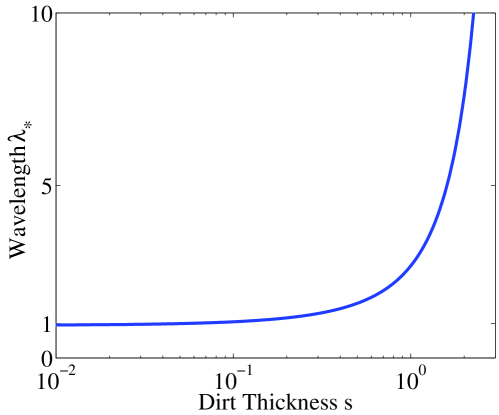
Figure 8 shows how dirt cuts off the instability, with fixed light intensity . When , the wavelength is close to the wavelength in the absence of dirt. However, the absorption of light by dirt becomes important for and the wavelength increases exponentially. As the wavelength increases, the growth rate of the instability decreases, and the instability becomes less readily observed.
2 Antisymmetric Mode
The antisymmetric mode involves variations in the thickness of the dirt. We must solve for the coupling between snow ablation and dirt motion. The solution is of the form
| (39) | |||||
| (40) |
where is the uniform dirt thickness at . Upon linearization, Equation 30 for the motion of dirt relates the perturbation amplitudes
| (41) |
The dispersion relation, to second order in , is
| (42) |
where is, defining and recalling is the dimensionless melting rate as a function of dirt thickness,
| (43) |
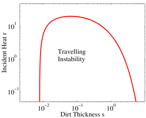
In the limit , this dispersion relation is identical to the symmetric mode. However, for increasing dirt thickness it contains effects from the dirt modulation. The term can be negative, leading to an oscillatory component to . Thus dirt can cause the instability to travel on the snow surface, in a region of phase space shown in Figure 9. For the typical solar brightness , any dirt thickness will induce travelling; therefore, most dirty snow surfaces should show this behavior. Qualitatively, this arises from the coupling of dirt motion to absorption. Dirt migrates to the highest point on the surface—but then the thicker dirt increases the ablation of that peak, and it ablates until it is no longer a local maximum. The positive and negative roots in the dispersion relation correspond to left and right moving modes. The existence of these travelling instabilities is an experimentally testable prediction.
Note that the equation is not well-behaved for . When the terms in the equation coupling motion of dirt to ablation vanish; the dispersion relation reduces to the expression for the symmetric mode above.
When is negative, we can find the fastest growing wavelength by looking at the real part of :
| (44) | |||||
| (45) |
E Thick Dirt Limit
The equations are considerably simplified in the limit of thick dirt . The effective albedo . Therefore the dirt instability is independent of any reflections; the quasi-linearized equations are truly linear in this limit. The thick-dirt instability is driven purely by dirt motion coupled to slower ablation under a thicker dirt layer. This instability is the linear precursor to the dirt cones of Figure 3.
Note that if light is not an important source of heat, the “thick dirt limit” is actually valid for all dirt thicknesses.
Replacing , the symmetric mode disappears. The background ablation rate . The dispersion relation is, to second order in ,
| (46) |
Here no imaginary component to the dispersion relation is present; it is a straightforward linear instability with one growing mode. The most unstable wavenumber is
| (47) |
For a fixed value of the heat input , the most unstable wavelength scales differently at small and large :
| (48) | |||||
| (49) |
The location of the minimum wavelength is determined by the dimensionless parameter , which represents how well the snow insulates per unit thickness. Therefore, even for optically thick dirt there is a change in the behavior, depending on the value of compared to the insulation parameter. Since typically , these limits are consistent.
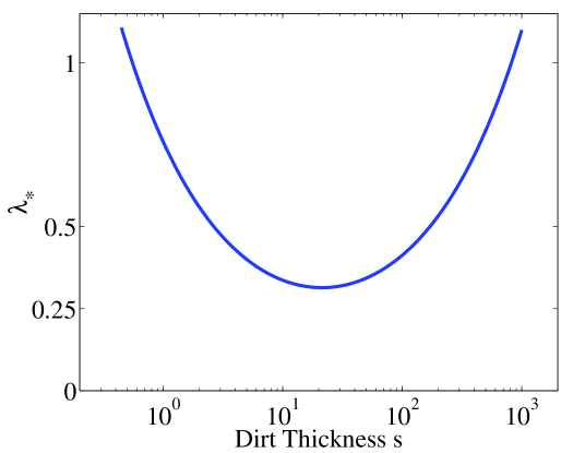
There is an optimal cm where the wavelength is smallest. Figure 10 illustrates this: it shows the unstable wavelength vs. dirt thickness for the typical , with the optimal cm. Comparing this figure to the thin-dirt instability, we see that when the wavelength will initially decrease, then increase beyond . The growth rate of this instability will be greatest where the wavelength is smallest.
III Discussion: Comparison to Experiment
This paper has presented work on a simple theory to describe the initial formation ablation structures such as suncups, penitentes and dirt cones. We have tried to make the model as simple as possible while including the essential physics. As we have shown, most parameters in the equations can be calculated or measured in experiments, allowing predictions with no free parameters. The exception is the effective diffusion coefficient , which we estimate using the value for light diffusion. However, we have not realistically treated the small-scale scattering of light in these schematic results.
At this point, the only quantitative comparison between this model and experiment is the prediction of ablation rate of a flat snow surface, compared with the data of Driedger in Figure 6. This measurement allows us to extract the dimensionless constant governing dirt insulation. The good agreement indicates we have captured the important effects of dirt.
The linear stability analysis of the equations shows the two types of instability described in the literature. The model predicts the dependence of the most unstable wavelength and characteristic growth rate on the experimental control parameters, predictions which could be tested. We argue that for little or no surface dirt, light reflection drives the instability. This instability is exponentially suppressed by a dirt layer, consistent with field observations. We predict travelling modes induced by a modulated dirt layer in this regime. The existence of such travelling modes is an experimentally testable new phenomenon.
In the presence of a thick layer of dirt, our analysis finds the insulation-driven instability, as expected. Here we predict an optimal dirt thickness where the instability is most easily observed, which depends on the thermal properties of the dirt.
The visually striking structures in the field are the larger structures: penitentes and dirt cones. Understanding the nonlinear regime of the model presented here is therefore of interest, and will be the subject of a future paper. The scale of both penitentes and dirt cones is typically larger than the size of smaller-amplitude structures. One way to explain this, which has been suggested from observations[8, 20], is that large structures grow at the expense of small ones. Such coarsening behavior is also apparent in preliminary work on the nonlinear regime of the model presented here.
The most obvious problem with the results here is that we have considered variation of the surface height in only one direction. Checking whether the results are the same for a realistic 2D surface is a necessary extension of this work. A better understanding of the small-scale cutoff is also important. In particular, we need to understand how using different representations of the short-scale physics affect the numerical predictions (of the fastest-growing wavelength, for example).
Because the model here is simplified, we have left out some physical effects which may be important in the experiment. Our treatment of light reflection considered single reflections only, which may be a bad approximation with the albedo is close to 1 (large amount reflected). In the field, the sun of course is not always high overhead—the variation of the angle of incident light over the course of the day might change the shapes. Other possibly important effects which can occur in field situations include other sources of heat transfer to the surface, gravity, and the deposition/removal of dirt. Better comparison with lab or field experiments should indicate which of these effects are most important to include.
Acknowledgements: I am grateful to John Wettlaufer and Norbert Untersteiner for comments on this paper. I thank Eric Nodwell and Tom Tiedje for discussing their work on this problem with me. I also wish to thank Michael Brenner, Daniel Fisher, David Weitz, Martine Benamar, David Lubensky, and David Nelson for helpful discussions, questions, and criticism. This work was supported by the NSF under grant DMS9733030.
REFERENCES
- [1] A. Post and E. R. LaChapelle. Glacier Ice. University of Washington Press, Seattle and London, 1971.
- [2] J. J. Rhodes, R. L. Armstrong, and S. G. Warren. Mode of formation of “ablation hollows” controlled by dirt content of snow. Journal of Glaciology, 33:135–139, 1987.
- [3] Charles Darwin. The Voyage of the Beagle, Chapter XV: Passage of the Cordillera. 1836. The quotation is from the entry for March 22, 1835.
- [4] F. E. Matthes. Ablation of snow-fields at high altitudes by radiant solar heat. Transactions of the American Geophysical Union, 15:380, 1934.
- [5] S. Hastenrath and B. Koci. Micro-morphology of the snow surface at the Quelccaya ice cap, Peru. Journal of Glaciology, 97:423, 1981.
- [6] V. M. Kotlyakov and I. M. Lebedeva. Nieve and ice penitentes. Their way of formation and indicative significance. Zeitschrift fur Gletscherkunde und Glazialgeologie, 10:111, 1974.
- [7] C. Troll. Busserschnee in den Hochgebirgen der Erde. Petermanns Geographische Mitteilungen, 1942. Erganzungsheft Nr. 240.
- [8] Louis Lliboutry. The origin of penitents. Journal of Glaciology, 2:331–338, 1954.
- [9] G. C. Amstutz. On the formation of snow penitentes. Journal of Glaciology, 3:304–311, 1958.
- [10] Douglas I. Benn and David J. A. Evans. Glaciers and Glaciation. Wiley, 1998.
- [11] J. Leighly. Cuspate surfaces of melting ice and firn. Geographical Review, 38:301, 1948.
- [12] W. E. Richardson. Dirt polygons. Weather, 9:117, 1954.
- [13] W. E. Richardson and R. D. M. Harper. Ablation polygons on snow—further observations and theories. Journal of Glaciology, 3:25, 1957.
- [14] A. Jahn and M. Klapa. On the origion of ablation hollows (polygons) on snow. Journal of Glaciology, 7:299, 1968.
- [15] I. Y. Ashwell and F. G. Hannell. Experiments on a snow-patch in the mountains of sweden. Journal of Glaciology, 6:135, 1966.
- [16] S. Takahashi, T. Fujii, and T. Ishida. Origin development of polygonal ablation hollows on a snow surface. Low Temperature Science Series A, (31):191, 1973.
- [17] S. Takahashi. A study on ablation hollows on a melting snow surface. Low Temperature Science Series A, (37):13, 1978.
- [18] The articles describing these experiments are in Japanese, which the author unfortunately does not understand.
- [19] Fanny Bullock Workman and William Hunter Workman. Peaks and Glaciers of Nun Kun. Charles Scribner’s Sons, New York, 1909.
- [20] J. W. Wilson. The initiation of dirt cones on snow. Journal of Glaciology, 2:281–287, 1953.
- [21] D. J. Drewry. A quantitative assessment of dirt-cone dynamics. Journal of Glaciology, 11:431–446, 1972.
- [22] C. L. Driedger. Effect of ash thickness on snow ablation. In P. W. Lipman and D. R. Mullineaux, editors, The 1980 Eruptions of Mount St. Helens, Washington, Geological Survey Professional Paper 1250, pages 757–760. United States Government Printing Office, 1981.
- [23] F. K. Ball. Dirt polygons on snow. Weather, 9:322, 1954.
- [24] C. Swithinbank. The origin of dirt cones on glaciers. Journal of Glaciology, 1:471, 1950.
- [25] Eric Nodwell and Thomas Tiedje. Personal communication. 2000.
- [26] Rhodes, Armstrong, and Warren [2] report two “initial attempts at modeling” published in German. Currently Nodwell and Tiedje are investigating the formation of suncups (personal communication). They consider in detail the scattering of light in the snowpack, and deduce a range of allowable suncup sizes from this.
- [27] W. J. Wiscombe and S. G. Warren. A model for the spectral albedo of snow. I: Pure snow. Journal of the Atmospheric Sciences, 37:2712–2733, 1980.
- [28] C. J. Van Der Veen. Fundamentals of Glacier Dynamics. A. A. Balkema, 1999.
- [29] Note that the 1 cm extinction length comes primarily from near-infrared wavelengths—the wavelengths of light which make the dominant contribution to the albedo and to ablation. Shorter wavelengths of visible light can penetrate much farther into the snow, 20 to 50 cm in old snow. See Wiscombe and Warren [27] for a thorough discussion of these effects.
- [30] One might think that diffusion of heat through the snow can be an important stabilizing factor. However, a simple calculation shows that this is not sufficient to provide a short-wavelength cutoff. I coupled temperature diffusion in the snow with heat conservation on the interface, assuming constant temperature in the air. This gives a dispersion relation with a term from reflections, as in the text, and a term proportional to from diffusion in the snow. As a result of this dependence, at short wavelengths the stabilization by heat diffusion is controlled by a dimensionless parameter , where is the temperature difference between the surface of the snow and deep in the snow, is the specific heat, and the latent heat. In order for heat diffusion in the snow to stabilize short wavelengths, we must have . However, K. Thus for a temperature difference of 10 C the parameter , which is far too low to provide the cutoff.
- [31] If most melting takes place during four hours of the day when the sun is most intense, this number gives 14 cm/day for the melting rate of the snow. It is useful to compare this to the field measurements of Kotlyakov and Lebedeva on penitente formation [6]. If we divide their measurement of the total radiation received in one day by the solar intensity at noon, we would get 3.5 hours estimated illumination time. They typically found snow height decreases of 6 cm/day. Thus our estimate may be too high, but is the correct order of magnitude. Kotlyakov and Lebedeva found 1.5 m high penitentes formed in 24 days.
- [32] When defined this way, is an extinction length for reflections, which differs by a factor of two from the transmission extinction length.
- [33] Drewry [21] deduces a value of 5.6 erg K for debris covering dirt cones, which he compares to other measurements for sand around 2 erg K.