Design Studies for a High Current Bunching System for CLIC Test Facility (CTF3) Drive Beam
Abstract
A bunching system is proposed for the initial stage (bunch spacing is 10 cm) of CTF3 which consists of one (two) 3 GHz prebuncher(s) and one 3GHz travelling wave (TW) buncher with variable phase velocities ( and 1) working at mode. Since the average macropulse beam current (3.5 A) at the exit of the TW buncher is rather high, inside the TW buncher one has to take the beam loading effect into consideration. By using PARMELA, it is shown numerically that the bunching system can provide the bunches which properties satisfy the design requirement of CTF3. The dimensions of the cavities in the two phase velocity regions are proposed. The transient beam loading effect and the multibunch transverse instabilities are studied numerically. It is concluded that higher order mode (HOM) couplers should be installed in the TW buncher with the loaded quality factor of the dipole mode lower than 80.
1 Introduction
CLIC is a two beam accelerator (TBA) based e+e- linear collider. The recently proposed CLIC drive beam scheme [1] makes CLIC more interesting. To demonstrate the feasibility of the new drive beam scheme and to test other technical aspects, CTF3 [2] has been proposed as a natural successor of the existing CTF2 to which LAL has actively collaborated and contributed in the past years [3][4]. In this paper we will restrict ourselves to the study of the bunching system for CTF3 which is a new subject of collaboration between LAL and CLIC group of CERN.
The bunching system under study consists of a 140 KV DC gun, one (two) prebuncher(s) of 3 GHz for the initial stage and one TW buncher of 3 GHz. In the following sections we will discuss the design of the travelling wave buncher considering the beam loading effect, the multibunch longitudinal and transverse beam dynamics in the TW buncher with the presence of long range wakefields, and the numerical simulations of the proposed bunching system by using PARMELA.
2 Beam loading effect
We start with the power diffusion equation in a linac
| (1) |
where , is the group velocity, is the quality factor, is the angular working frequency, is the power flow inside the structure, is the amplitude of the synchronous accelerating field, and is the average beam current during the rf pulse. By using the initial condition , one gets:
| (2) |
where is the shunt impedance of the accelerating mode, and is the input power from the rf source, and are kept constant within the accelerating structure, is the phase of the accelerating field ( corresponds to the maximum acceleration), and this expression was first obtained by A.J. Lichtenberg [5].
To have good energy transfer efficiency and energy gain at the same time, one requires (fully beam loading condition):
| (3) |
where is the length of the accelerating section. When the ohmic losses on the structure wall are small the fully beam loaded condition results in
| (4) |
For a given , , and , one gets from eq. 4 and one can determine the geometry of the disk-loaded structure by solving the following equations:
| (5) |
where and can be expressed analytically as [6][7]:
| (6) |
| (7) |
| (8) |
| (9) |
where , , , , and are defined in Fig. 1, , is the wavelength in free space, and is the phase shift per cell.
Now we make a rough design for the TW buncher working at 3 GHz (R m) and 2/3 mode. If one takes MV/m, A, m, one finds MW and the structure dimensions given in Table 1. The structure has two sections with phase velocities and , respectively. The number of the cells of is four which has been determined by the beam dynamics simulations of PARMELA.
| Cell type | D (m) | h (m) | a (m) | |
|---|---|---|---|---|
| 0.025 | 0.0137 | 0.0146 | 0.031 | |
| 0.033 | 0.02 | 0.016 | 0.029 |


3 Beam dynamics
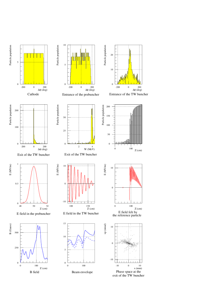
The design goal and the layout of the bunching system are shown in Fig. 2, and in Fig. 3 [8][9]. A multibunch beam dynamics study shows that for the initial stage of CTF3 there is no need to damp the dipole modes in the TW buncher; however, for the final phase (bunch spacing is 20 cm) the dipole modes in the TW buncher have to be damped to as shown in Fig. 4. By using PARMELA one gets the bunched beam parameters at the exit of the TW buncher. Now we only show the simulation results in Fig. 5 for the single 3 GHz prebuncher case. The DC current coming from the cathode is 7 A and during 2, 500 particles have been tracked. For the observing window of 20 degree centered around the bunch current peak, one gets 322 particles transmitted at the exit of the TW buncher, the normalized rms emittance is 51 mm.mrad, the rms energy spread is 0.12 MeV, the energy of the reference particle is 3.8 MeV, and the longitudinal rms bunch length is 4.4 ps. In future simulations two fully beam loaded structures will be added after the TW buncher to push the beam energy up to about 26 MeV.

4 Conclusion
We have given a preliminary design for the TW buncher. By using PARMELA the bunching system consisting one (two) prebuncher(s) and a TW buncher has been simulated and the results are satisfactory. More simulations will be done to determine how many prebunchers are to be used and to include two accelerating sections to accelerate the beam to about 26 MeV. Multibunch beam dynamic simulation results show that the loaded quality factors of the dipole modes in the TW buncher have to be lower than 80.
5 Acknowledgement
We thank L. Rinolfi and E. Jensen for providing useful information and discussions.
References
- [1] H. Braun, et al., CLIC Note 367.
- [2] CLIC study team, CLIC Note 402
- [3] G. Bienvenu and J. Gao, EPAC96, Barcelona, 1996, p. 495.
- [4] J. Gao, LAL-SERA-99-36.
- [5] A. J. Lichtenberg, Rev. Sci. Instr., 33, No. 3 (1962), p. 395.
- [6] J. Gao, Nucl. Instr. and Methods, A381 (1996), p. 174.
- [7] J. Gao, Particle Accelerators, Vol. 43 (4) (1994), p. 235.
- [8] L. Rinolfi, Proceedings of LC99, Frascati, Italy, Oct. 1999.
- [9] Meeting note between H. Braun and D. Yeremian, Feb. 28-29, 2000 at SLAC.