First Observation of Self-Amplified Spontaneous Emission in a Free-Electron Laser at 109 nm Wavelength ††thanks: Dedicated to Bjørn H. Wiik, 17.2.1937 – 26.2.1999
Abstract
Abstract
We present first observation of Self-Amplified Spontaneous Emission
(SASE) in a free-electron laser (FEL) in the Vacuum Ultraviolet regime
at 109 nm wavelength (11 eV). The observed free-electron laser gain
(approx. 3000) and the radiation characteristics, such as dependency on
bunch charge, angular distribution, spectral width and intensity
fluctuations all corroborate the present models for SASE FELs.
I Introduction
X-ray lasers are expected to open up new and exciting areas of basic and applied research in biology, chemistry and physics. Due to recent progress in accelerator technology the attainment of the long sought-after goal of wide-range tunable laser radiation in the Vacuum-Ultraviolet and X-ray spectral regions is coming close to realization with the construction of free-electron lasers (FEL) [1] based on the principle of Self-Amplified Spontaneous Emission (SASE) [2, 3]. In a SASE FEL lasing occurs in a single pass of a relativistic, high-quality electron bunch through a long undulator magnet structure.
The radiation wavelength of the first harmonic of FEL radiation is related to the period length of a planar undulator by
| (1) |
where is the relativistic factor of the electrons, the undulator parameter and the peak magnetic field in the undulator. Equation (1) exhibits two main advantages of the free-electron laser: the free tunability of the wavelength by changing the electron energy and the possibility to achieve very short radiation wavelengths.
For most FELs presently in operation [4], the electron beam quality and the undulator length result in a gain of only a few percent per undulator passage, so that an optical cavity resonator and a synchronized multi-bunch electron beam have to be used. At very short wavelengths, normal-incidence mirrors of high reflectivity are unavailable. Therefore the generation of an electron beam of extremely high quality in terms of emittance, peak current and energy spread, and a high precision undulator of sufficient length are essential. Provided the spontaneous radiation from the first part of the undulator overlaps the electron beam, the electromagnetic radiation interacts with the electron bunch leading to a density modulation (micro-bunching) which enhances the power and coherence of radiation. In this “high gain mode” [5, 6, 7], the radiation power grows exponentially with the distance along the undulator
| (2) |
where is the field gain length, the effective input power (see below), and the input coupling factor [6, 7]. is equal to 1/9 in one-dimensional FEL theory with an ideal electron beam. Typical parameters for a SASE FEL operating in the VUV wavelength range are: of about a few Watts and power gain at saturation, , of about .
Since the desired wavelength is very short, there is no laser tunable over a wide range to provide the input power . Instead, the spontaneous undulator radiation from the first part of the undulator is used as an input signal to the downstream part. FELs based on this Self-Amplified-Spontaneous-Emission (SASE) principle are presently considered the most attractive candidates for delivering extremely brilliant, coherent light with wavelength in the Ångström regime [8, 9, 10, 11]. Compared to state-of-the-art synchrotron radiation sources, one expects full transverse coherence, up to 4-6 orders of magnitude larger average brilliance, and up to 8-10 orders of magnitude larger peak brilliance at pulse lengths of about 200 fs FWHM. Recently there have been important advances in demonstrating a high-gain SASE FEL at 12 m wavelength [12] and at 530 nm wavelength [13].
II Experimental set-up
The experimental results presented in this paper have been achieved at the TESLA Test Facility (TTF) Free-Electron Laser [14] at the Deutsches Elektronen-Synchrotron DESY. The TESLA (TeV-Energy Superconducting Linear Accelerator) collaboration consists of 39 institutes from 9 countries and aims at the construction of a 500 GeV (center-of-mass) e+/e- linear collider with an integrated X-ray laser facility [10]. Major hardware contributions to TTF have come from Germany, France, Italy, and the USA. The goal of the TTF FEL is to demonstrate SASE FEL emission in the VUV and, in a second phase, to build a soft X-ray user facility [15, 16].
| Parameter | Measured value |
|---|---|
| beam energy | MeV |
| rms energy spread | MeV |
| rms transverse beam size | m |
| normalized emittance, | mrad mm |
| electron bunch charge | 1 nC |
| peak electron current | A |
| bunch spacing | 1 s |
| repetition rate | 1 Hz |
| undulator period, | 27.3 mm |
| undulator peak field | 0.46 T |
| effective undulator length | 13.5 m |
| radiation wavelength, | 109 nm |
| FEL gain | |
| FEL radiation pulse length | 0.3-1 ps |
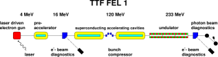
The layout is shown in Fig. 1. The main parameters for FEL operation are compiled in Table I. The injector is based on a laser-driven 1-cell rf gun electron source operating at 1.3 GHz [17]. It uses a Cs2Te cathode [18] and can generate bunch charges more than 10 nC at 1 MHz repetition rate. A loading system allows mounting and changing of cathodes while maintaining ultra-high vacuum conditions [18]. The cathode is illuminated by a train of UV laser pulses generated in a mode-locked solid-state laser system [19] synchronized with the rf. An energy of up to 50 J with a pulse-to-pulse variation of 2% (rms) is achieved. The UV pulse length measured with a streak camera is ps . The rf gun is operated with a peak electric field of 37 MV/m on the photocathode. The rf pulse length was limited to 100 s and the repetition rate to 1 Hz for machine protection reasons. The gun section is followed by a 9-cell superconducting cavity, boosting the energy to 16 MeV. The superconducting accelerator structure has been described elsewhere [20].
The undulator is a fixed 12 mm gap permanent magnet device using a combined function magnet design [21] with a period length of = 27.3 mm and a peak field of = 0.46 T, resulting in an undulator parameter of . Integrated quadrupole structures produce a gradient of 12 T/m superimposed on the periodic undulator field in order to focus the electron beam along the undulator. The undulator system is subdivided into three segments, each 4.5 m long and containing 10 quadrupole sections to build up 5 full focusing-defocusing (FODO) cells. The FODO lattice periodicity runs smoothly from segment to segment. There is a spacing of 0.3 m between adjacent segments for diagnostics. The total length of the system is 14.1 m. The vacuum chamber incorporates 10 beam position monitors and 10 orbit correction magnets per segment, one for each quadrupole [22, 23].
For optimum overlap between the electron light beams, high precision on the magnetic fields and mechanical alignment are required. The undulator field was adjusted such that the expected rms deviations of the electron orbit should be smaller than 10 m at 300 MeV [24]. The beam orbit straightness in the undulator is determined by the alignment precision of the superimposed permanent-magnet quadrupole fields which is better than 50 m in both vertical and horizontal direction. The relative alignment of the three segments is accomplished with a laser interferometer to better than 30 m [25].
Different techniques have been used to measure the emittance of the electron beam [26]: Magnet optics scanning (“quadrupole scans”), tomographic reconstruction of the phase space including space charge effects, and the slit system method. All methods use optical transition radiation emitted from aluminum foils to measure the bunch profiles and yield values for the normalized emittance of () mrad mm for a bunch charge of 1 nC at the exit of the injector. The emittance in the undulator, as determined from quadrupole scans and from a system of wire scanners was typically between 6 and 10 mrad mm (in both horizontal and vertical phase space). It should be noted that the measurement techniques applied determine the emittance integrated over the entire bunch length. However, for FEL physics, the emittance of bunch slices much shorter than the bunch length is the relevant parameter. It is likely that, due to spurious dispersion and wakefields, the bunch axis is tilted about a transverse axis such that the projected emittance is larger than the emittance of any slice. Based on these considerations we estimate the normalized slice emittance in the undulator at () mrad mm.
A bunch compressor is inserted between the two accelerating modules, in order to increase the peak current of the bunch up to 500 A, corresponding to 0.25 mm bunch length (rms) for a 1 nC bunch with Gaussian density profile. Experimentally, it is routinely verified that a large fraction of the bunch charge is compressed to a length below 0.4 mm (rms) [27]. There are indications that the core is compressed even further. We estimate the peak current for the FEL experiment at () A. Coherent synchrotron radiation in the magnetic bunch compressor may affect the emittance and the energy spread at such short bunch lengths [28].
III FEL measurements
A strong evidence for the FEL process is a large increase in the on-axis radiation intensity if the electron beam is injected such that it overlaps with the radiation during the entire passage through the undulator. Fig. 2 shows the intensity passing a 0.5 mm iris, located on axis 12 m downstream of the undulator, as a function of the horizontal beam position at the undulator entrance. The observed intensity inside a window of m around the optimum beam position is a factor of more than 100 higher than the intensity of spontaneous radiation. A PtSi photodiode was used integrating over all wavelengths. Note that the vacuum chamber diameter in the undulator (9.5 mm) is much larger than the beam diameter (300 m).
SASE gain is expected to depend on the bunch charge in an extremely nonlinear way. Fig. 3 shows the measured intensity on axis as a function of bunch charge , while the beam orbit is kept constant for optimum gain. The solid line indicates the intensity of the spontaneous undulator radiation multiplied by a factor of 100. The strongly nonlinear increase of the intensity as a function of bunch charge is a definite proof of FEL action. The gain does not further increase if the bunch charge exceeds some 0.6 nC. This needs further study, but it is known that the beam emittance becomes larger for increasing thus reducing the FEL gain.


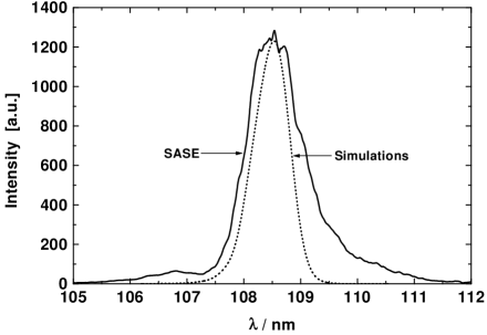
The wavelength spectrum of the radiation (taken on axis at maximum FEL gain) is presented in Fig. 4. The central wavelength of 108.5 nm is consistent with the measured beam energy of () MeV and the known undulator parameter , see Eq. (1). The intensity gain determined with the CCD camera of the spectrometer is in agreement with the photodiode result.
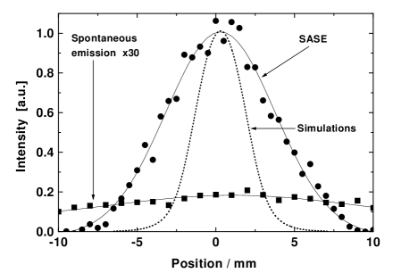
A characteristic feature of SASE FELs is the concentration of radiation power into a cone much narrower than that of wavelength integrated undulator radiation, whose opening angle is in the order of . Measurements done by moving the 0.5 mm iris horizontally together with the photodiode confirm this expectation, see Fig. 5. The spontaneous intensity is amplified by a factor of 30 to be visible on this scale.
In order to study which section of the undulator contributes most to the FEL gain, we applied closed orbit beam bumps to different sections of the undulator, thus disturbing the gain process at various locations along the undulator. It was seen that practically the entire undulator contributes, but with some variation in local gain. Some improvement in the over-all gain should be possible by optimizing the settings of the 30 orbit correction coils which have not been touched so far.
To determine the absolute FEL intensity, the photodiode is firstly calibrated using the known intensity of undulator radiation. For the iris diameter of 3 mm used for spontaneous emission and averaging the solid angle over the source positions inside the undulator, we get . About 70 pJ is accepted within the iris at the first harmonic of the spontaneous undulator radiation per 1 nC bunch charge. The SASE FEL signal was measured using an iris diameter of 0.5 mm, the signal was larger by a factor of about 5. Hence, the energy flux is 2 nJ/mm2 at the location of the detector and the on-axis flux per unit solid angle is about 0.3 J/sr (assuming a source position at the end of the undulator). This value was used as input for the numerical simulation of the SASE FEL performed with the code FAST [29]. The longitudinal profile of the bunch current was assumed to be Gaussian with an rms length of 0.25 mm. The transverse distribution of the beam current density was also taken to be Gaussian. Calculations have been performed for a Gaussian energy spread of 0.1%. According to numerical simulation one of the most critical parameters for FEL operation is the normalized emittance that was varied in the simulations between 5 and 10 mrad mm. A first conclusion from our calculations is that the TTF FEL operates in the high-gain linear regime where the power grows exponentially along the undulator. The contribution of the fundamental transverse mode TEM00 to the total power seems to dominate, so that Eq. (2) applies.
Our calculations show that the length at which a level of energy flux of 0.3 J/sr is obtained strongly depends on emittance, but the number of gain lengths is roughly the same in all cases and is about 5. Figs. 4 and 5 include typical theoretical spectral and angular distributions as calculated by our numerical simulation. In both cases experimental curves are wider than the simulation results. A possible source of the widening is energy and orbit jitter, since the experimental curves are results of averaging over many bunches.
The FEL gain is defined as the ratio of output to input power, see Eq. (2). It is a characteristic of the FEL amplifier and should depend only on the parameters of the electron beam and the undulator but not on the type of input signal. For a FEL amplifier seeded by an external laser the input power is well defined. For an FEL amplifier starting from noise (i.e. a SASE FEL) the effective power of shot noise can be defined as the power of optimally focused seeding radiation yielding the same output power. The gain is then simply , see Eq. (2). With an input coupling factor A 0.1, the FEL gain can be estimated at . The uncertainty is estimated at a factor of 3 (i.e. ) and is mainly due to the imprecise knowledge of the longitudinal beam profile.
It is essential to realize that the fluctuations seen in Figs. 2 and 3 are not primarily due to unstable operation of the accelerator but are inherent to the SASE process. Shot noise in the electron beam causes fluctuations of the beam density, which are random in time and space [30]. As a result, the radiation produced by such a beam has random amplitudes and phases in time and space and can be described in terms of statistical optics. In the linear regime of a SASE FEL, the radiation pulse energy measured in a narrow central cone (opening angle rad in our case) at maximum gain is expected to fluctuate according to a gamma distribution [31],
| (3) |
where is the mean energy, is the gamma function with argument , and is the normalized variance of . The parameter corresponds to the number of longitudinal optical modes. Note that the same kind of statistics applies for completely chaotic polarized light, in particular for spontaneous undulator radiation.
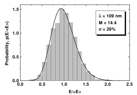
For these statistical measurements the signals from 3000 radiation pulses have been recorded, with the small iris (0.5 mm diameter) in front of the photo diode to guarantee that transversely coherent radiation pulses are selected. As one can see from Fig. 6, the distribution of the energy in the radiation pulses is quite close to the gamma distribution. The relative rms fluctuations are about 26% corresponding to . One should take into account that these fluctuations arise not only from the shot noise in the electron beam, but the pulse-to-pulse variations of the beam parameters can also contribute to the fluctuations. Thus, the value can be considered as a lower limit for the number of longitudinal modes in the radiation pulse. Using the width of radiation spectrum we calculate the coherence time [31] and find that the part of the electron bunch contributing to the SASE process is at least 100 m long. ¿From the quality of the agreement with the gamma distribution we can also conclude that the statistical properties of the radiation are described with Gaussian statistics. In particular, this means that there are no FEL saturation effects.
ACKNOWLEDGMENTS
Fundamental work on high accelerating gradients in superconducting cavities at Wuppertal University was essential for the successful construction of the first TTF accelerating modules. We are grateful for the invaluable support by the technical staff of the participating groups. Support by the Moscow Physical Engineering Institute and by the Institute for Nuclear Studies, Swierk, Poland, is gratefully acknowledged.
REFERENCES
- [1] J.M.J. Madey, J. Appl. Phys. 42, 1906 (1971).
- [2] A.M. Kondratenko, E.L. Saldin, Part. Accelerators 10, 207 (1980)
- [3] R. Bonifacio, C. Pellegrini, L.M. Narducci, Opt. Commun. 50, 373 (1984)
- [4] W.B. Colson, Nucl. Instr. and Meth. A429, 37-40 (1999).
- [5] K.J. Kim, Phys. Rev. Lett. 57, 1871 (1986)
- [6] S. Krinsky, L.H. Yu, Phys. Rev. A35, 3406 (1987)
- [7] E.L. Saldin, E.A. Schneidmiller, M.V. Yurkov, “The Physics of Free Electron Lasers”, Springer (1999) and references therein
- [8] H. Winick, et al., Proc. PAC Washington and SLAC-PUB-6185, (1993)
- [9] R. Brinkmann, et al., Nucl. Instr. and Meth. A 393, 86-92 (1997)
- [10] R. Brinkmann, G. Materlik, J. Rossbach, A. Wagner (eds.), DESY 1997-048 and ECFA 1997-182 (1997)
- [11] H.-D. Nuhn, J. Rossbach, Synchrotron Radiation News 13, No. 1, 18 - 32 (2000)
- [12] M. Hogan, et al., Phys. Rev. Lett. 81, 4867 (1998)
- [13] S. Milton, et al., “Observation of Self-Amplified Spontaneous Emission and Exponential Growth at 530 nm”, submitted to Phys. Rev. Lett. (2000)
- [14] W. Brefeld, et al., Nucl. Instr. and Meth. A393, 119-124 (1997)
- [15] T. Åberg, et al., A VUV FEL at the TESLA Test Facility at DESY, Conceptual Design Report, DESY Print TESLA-FEL 95-03 (1995)
- [16] J. Rossbach, Nucl. Instr. and Meth. A 375, 269 (1996)
- [17] J.-P. Carneiro, et al., Proc. 1999 Part. Acc. Conf., New York, 2027-2029 (1999)
- [18] P. Michelato, et al., Nucl. Instr. and Meth. A445, 422 (2000)
- [19] I. Will, S. Schreiber, A. Liero, W. Sandner, Nucl. Instr. and Meth. A445, 427 (2000)
- [20] H. Weise, Proc. 1998 Linac Conf. Chicago, 674-678 (1998)
- [21] Y.M. Nikitina, J. Pflüger, Nucl. Instr. and Meth. A375, 325 (1996)
- [22] U. Hahn, J. Pflüger, G. Schmidt, Nucl. Instr. and Meth. A429, 276 (1999)
- [23] U. Hahn, et al., Nucl. Instr. and Meth. A445, 442 (2000)
- [24] J. Pflüger, Nucl. Instr. and Meth. A445, 366 (2000)
- [25] J. Pflüger, H. Lu, T. Teichmann, Nucl. Instr. and Meth. A429 386 (1999)
- [26] H. Edwards, et al., Proc. 1999 FEL Conf., Hamburg
- [27] M. Geitz, G. Schmidt, P. Schmüser, G.V. Walter, Nucl. Instr. and Meth. A445, 343 (2000)
- [28] M. Dohlus, A. Kabel, T. Limberg, Proc. 1999 Part. Acc. Conf., New York, 1650-1652 (1999)
- [29] E.L. Saldin, E.A. Schneidmiller, M.V. Yurkov, Nucl. Instr. and Meth. A 429, 233 (1999)
- [30] R. Bonifacio, et al., Phys. Rev. Lett. 73, 70 (1994)
- [31] E.L. Saldin, E.A. Schneidmiller, M.V. Yurkov, Opt. Commun. 148 383 (1998)