Parameter Sets for 10 TeV and 100 TeV Muon Colliders, and their Study at the HEMC’99 Workshop ††thanks: To appear in Proc. HEMC’99 Workshop – Studies on Colliders and Collider Physics at the Highest Energies: Muon Colliders at 10 TeV to 100 TeV; Montauk, NY, September 27-October 1, 1999, web page http://pubweb.bnl.gov/people/bking/heshop. This work was performed under the auspices of the U.S. Department of Energy under contract no. DE-AC02-98CH10886.
Abstract
A focal point for the HEMC’99 workshop was the evaluation of straw-man parameter sets for the acceleration and collider rings of muon colliders at center of mass energies of 10 TeV and 100 TeV. These self-consistent parameter sets are presented and discussed. The methods and assumptions used in their generation are described and motivations are given for the specific choices of parameter values. The assessment of the parameter sets during the workshop is then reviewed and the implications for the feasibility of many-TeV muon colliders are evaluated. Finally, a preview is given of plans for iterating on the parameter sets and, more generally, for future feasibility studies on many-TeV muon colliders.
I Introduction
Self-consistent example parameter sets for the acceleration and collider ring parameters of many-TeV muon colliders were an important focal point for the discussions at the HEMC’99 Workshop – “Studies on Colliders and Collider Physics at the Highest Energies: Muon Colliders at 10 TeV to 100 TeV”, held at Montauk, NY from September 27-October 1, 1999. They served as straw-man examples to be criticized, fleshed-out and improved upon by the accelerator experts attending the workshop, and the physics-related parameters helped the experimental and theoretical physicists at the workshop in their evaluations and comments on the physics potential of such colliders.
Three acceleration and collider parameter sets were used at HEMC’99: one at a center-of-mass energy of 10 TeV (set A) and two at 100 TeV (sets B and C). The collider ring and accelerator parameters are presented in tables 1 and 2, respectively. For comparison, table 1 also includes the parameter ranges for the lower energy muon colliders that have been studied by the Muon Collider Collaboration (MCC). This paper describes the methods used to generate the parameter sets, details the motivations and assumptions for the specific choices of parameters and summarizes the evaluations, conclusions and suggestions for the parameter sets that were given by the workshop participants.
In more detail, the collider ring parameters are presented first, in section II, since they were considered the more critical of the two for assessing the feasibility of many-TeV muon colliders. They also determine the initial assumptions used for the acceleration parameters, which are then discussed in section III. The level of understanding advanced substantially during the workshop, and section IV goes over the issues and viewpoints raised during the workshop as well as referencing the more detailed studies that are included elsewhere in these proceedings and discussing their impact on our assessment of the parameter sets. Finally, the Outlook and Conclusions section, section V, summarizes the results discussed in the preceding section in the more general context of what they imply for the feasibility of many-TeV muon colliders. This concluding section also discusses the outlook for iterations and refinements on the parameter sets and, more generally, previews some plans for further studies on many-TeV muon colliders.
II Straw-man Muon Collider Ring Parameter Sets at 10 TeV and 100 TeV
| parameter set | A | B | C | |
| center of mass energy, | 0.1 to 3 TeV | 10 TeV | 100 TeV | 100 TeV |
| additional description | MCC status report | evol. extrap. | evol. extrap. | ultracold beam |
| collider physics parameters: | ||||
| luminosity, [] | 0.5 | 10 | 10 | 1000 |
| dt [] | 0.08540 | 10 000 | 10 000 | |
| No. of events/det/year | 65010 000 | 8700 | 87 | 8700 |
| No. of 100 GeV SM Higgs/year | 4000600 000 | |||
| CoM energy spread, [] | 0.021.1 | 0.42 | 0.080 | 0.071 |
| collider ring parameters: | ||||
| circumference, C [km] | 0.356.0 | 15 | 100 | 100 |
| ave. bending B field [T] | 3.05.2 | 7.0 | 10.5 | 10.5 |
| beam parameters: | ||||
| ( or) /bunch, | 2.04.0 | 3.0 | 0.80 | 0.19 |
| ( or) bunch rep. rate, [Hz] | 1530 | 27 | 7.9 | 65 |
| 6-dim. norm. emit., ] | 170170 | 85 | 10 | |
| ] | 2.02.0 | 1.0 | 0.12 | |
| P.S. density, ] | 1.22.4 | 3.5 | 8.0 | 19 000 |
| x,y emit. (unnorm.) [] | 3.5620 | 0.81 | 0.018 | |
| x,y normalized emit. [] | 50290 | 38 | 8.7 | 0.21 |
| long. emittance [] | 21 | 47 | 8.1 | |
| fract. mom. spread, [] | 0.0301.6 | 0.60 | 0.113 | 0.100 |
| relativistic factor, | 47314 200 | 47 300 | 473 000 | 473 000 |
| time to beam dump, | no dump | no dump | 1.0 | 1.0 |
| effective turns/bunch | 450780 | 1040 | 1350 | 1350 |
| ave. current [mA] | 1730 | 55 | 4.0 | 7.8 |
| beam power [MW] | 1.029 | 131 | 100 | 198 |
| synch. rad. critical E [MeV] | 0.012 | 1.75 | 1.75 | |
| synch. rad. E loss/turn [GeV] | 0.017 | 25 | 25 | |
| synch. rad. power [MW] | 0.010 | 0.91 | 99 | 195 |
| beam + synch. power [MW] | 1.029 | 130 | 200 | 390 |
| power density into magnet liner [kW/m] | 1.01.7 | 4.3 | 1.2 | 2.4 |
| interaction point parameters: | ||||
| spot size, | 3.3290 | 1.3 | 0.21 | 0.015 |
| bunch length, [mm] | 3.0140 | 2.2 | 2.5 | 0.49 |
| [mm] | 3.0140 | 2.1 | 2.5 | 0.49 |
| ang. divergence, [mrad] | 1.12.1 | 0.63 | 0.086 | 0.030 |
| ip compensation factor: | 1 | 1 | 1 | 10 |
| beam-beam tune disruption, | 0.0150.051 | 0.085 | 0.100 | 0.100 |
| pinch enhancement factor, | 1.001.01 | 1.08 | 1.11 | 1.11 |
| beamstrahlung frac. E loss/collision | negligible | |||
| final focus lattice parameters: | ||||
| max. poletip field of quads., [T] | 612 | 15 | 20 | 20 |
| max. full aper. of quad., [cm] | 1424 | 22 | 19 | 6.6 |
| quad. gradient, [T/m] | 5090 | 140 | 210 | 610 |
| 1.5150 | 580 | 19 000 | 64 000 | |
| ff demag., | 2207100 | 17 000 | 89 000 | 360 000 |
| chrom. quality factor, | 0.00711 | 10 | 10 | 45 |
| neutrino radiation parameters: | ||||
| collider reference depth, D[m] | 10300 | 100 | 100 | 100 |
| ave. rad. dose in plane [mSv/yr] | 0.02 | 2.3 | 10 | 20 |
| str. sec. len. for 10x ave. rad. [m] | 1.32.2 | 1.1 | 1.0 | 4.2 |
| beam distance to surface [km] | 1162 | 36 | 36 | 36 |
| beam radius at surface [m] | 4.424 | 0.8 | 0.08 | 0.08 |
II.1 Generation of the Parameter Sets
The parameter sets in table 1 were generated through iterative runs of a stand-alone computer program, as has been described previously epac98 ; pac99he .
The most important physics parameter for a specified collider energy is the luminosity, . This is derived in terms of several input parameters according to the formula epac98 :
| (1) | |||||
where the input variables are the CoM energy (), the collider ring circumference (C), the beams’ fractional momentum spread () and 6-dimensional invariant emittance (), the time until the beams are dumped (), the bunch repetition frequency (), the initial number of muons per bunch (), and the beam divergence at the interaction point (). Units in equations throughout this paper are given in square brackets. (The time-to-dump, , is given in units of the boosted muon lifetime, .) This formula uses the standard assumption from the Muon Collider Collaboration that the ratio of transverse to longitudinal emittances can be manipulated freely in the muon cooling channel to maximize the luminosity for a given . The pinch enhancement factor, , is very close to unity (see table 1), and the numerical coefficient in equation 1 includes a geometric correction factor of 0.76 for the non-zero bunch length, (the “hourglass effect”) .
In practice, the muon beam power and current are limiting parameters for energy frontier muon colliders, so the parameters are actually chosen to optimize the “specific luminosity”:
| (2) |
The luminosity is then determined from the choice of beam current that corresponds to the highest plausible beam powers.
Several further parameters in table 1 have been derived from the input parameters that determine the luminosity. These include, for example, the beam-beam tune disruption parameter, . Other output parameters require additional modeling assumptions and/or further input parameters epac98 ; pac99he . Examples include some of the output parameters for the final focus; these require both the input of a reference pole-tip magnetic field for the final focus quadrupoles () and a much simplified model for the final focus magnet lattice that is a linearized extrapolation from existing final focus lattice designs for lower energy muon colliders.
The physics parameters in table 1 include two examples of event sample sizes. As is discussed in references pr98 ; hemc99intro these give an indication of the physics potential corresponding to the specified luminosity and energy. Briefly, the number of events gives a benchmark estimate of the discovery potential for elementary particles at the full CoM energy of the collider, while the production of hypothesized 100 GeV Higgs particles indicates roughly how the colliders might perform in studying physics at a lower energy scale.
II.2 Optimization of the 10 TeV and 100 TeV Parameter Sets
The Initial Choice of Energies
The two energies for the parameter sets, TeV and 100 TeV, were chosen because they bracket that energy decade. The 10 TeV lower limit was chosen to be well above the highest energy that had been studied in detail, namely, TeV for the Snowmass’96 workshop Snowmass . Further, the neutrino radiation for very high luminosity colliders at 10 TeV and above is high enough to rule out siting them at an existing laboratory, as is covered elsewhere in these proceedings hemc99nurad . This necessitates a fresh outlook for the design optimization of the colliders that is free from site-specific preconceptions involving existing laboratories, which was considered a good thing.
The choice of the upper energy limit was more technically constrained. For the 100 TeV parameter sets, the synchrotron radiation power had risen to become almost identical to the beam power, signaling a clear upper bound for the feasibility of circular colliders.
To preview later discussion, it is noted that our understanding of the constraints on high energy muon colliders advanced during the workshop, as will be covered in section IV. An additional constraint on the maximum possible energies for circular muon colliders was discovered Telnovsynch , due to beam heating arising from the quantum mechanical nature of the synchrotron radiation. On the other hand, the future prospects of many-TeV muon colliders were given a boost when the possible potential for linear colliders at even higher energies was uncovered Zimmermann .
Balancing Luminosity against Technical Difficulty
After deciding on the collision energies, it was then decided that the 10 TeV (set A) and the first of the 100 TeV parameter sets (set B) should assume only evolutionary changes in technology from the base-line parameters that have been previously posited for lower energy colliders status . For example, the assumed 6-dimensional emittances are factors of 3.5 (10 TeV) or 50 (100 TeV) smaller than the value that is normally used in Muon Collider Collaboration scenarios for first generation muon colliders. The smaller emittances assume that the performance of the muon cooling channel will be progressively improved through further design optimization, stronger magnets, higher gradient rf cavities and other technological advancements and innovations.
The second parameter set at 100 TeV (i.e., set C) encouraged study on some of the possibilities for using exotic technologies to improve the potential performance of future many-TeV colliders. The additional assumed advances increased the luminosity by two orders of magnitude over the evolutionary parameter set at 100 TeV, to what would be a very impressive . (The luminosity should ideally rise as , as is explained in reference hemc99intro .) The hypothesized technical advances included:
-
1.
exotic cooling, to obtain a phase space density that is a further 3 orders of magnitude larger than the assumption for the evolutionary parameter set at 100 TeV
-
2.
charge compensation at the interaction point (ip), to reduce the effective charge by a factor of 10. This assumption led rather directly to a corresponding increase in the luminosity by about a factor of 10.
-
3.
more aggressive final focus parameters were included to allow for potential improvements in the final focus design, perhaps using exotic focusing technologies
-
4.
the beam power was almost doubled from the evolutionary parameter set (B), to “top up” the luminosity to .
Final Focus Constraints
The final focus design may well present the most difficult design challenges that are relatively specific to high energy muon colliders. (This is to be contrasted with the muon cooling channel, which is a formidable challenge for all muon colliders.) References epac98 and pac99he have previously addressed the general design constraints and issues for final focus designs at many-TeV muon colliders.
To re-cap the discussion of references epac98 and pac99he , higher energies demand progressively stronger focusing to generate the smaller spot sizes needed to increase the luminosity. Two simply defined parameters were used as benchmarks to obtain final focus specifications that might provide plausible starting assumptions for first attempts at magnet lattice designs. Firstly, an overall beam demagnification parameter is defined epac98 in terms of one of the Courant-Snyder lattice parameters, , as
| (3) |
This is a dimensionless parameter that gauges the strength of the focusing. The size of should be closely correlated with fractional tolerances in magnet uniformity, residual chromaticity, etc., where the chromaticity is a measure of the change in response of the final focus to off-momentum particles. Secondly, a high residual chromaticity can be compensated for by decreasing the fractional momentum spread of the beams, . This suggests that another measure of the final focus difficulty might come from the product of the demagnification and momentum spread,
| (4) |
where has been referred to epac98 as the “chromaticity quality factor”.
In generating the parameter sets, the values of and were compared to those for existing and final focus designs, as was discussed in references epac98 ; pac99he . In practice, slightly more attention was paid to than to in obtaining the final parameters. It can be seen from table 1 that the two “evolutionary” parameter sets, A and B, were constrained to the value , which is very similar to the calculated value, , for the final focus lattice design of the 3 TeV collider in reference status . A more aggressive value, , was allowed for in the second parameter set at 100 TeV.
It is noted that the parameter sets at these high energies are always limited by and it is useful and straightforward to rewrite equations 1 and 2 in the form:
| (5) |
which has no explicit dependence on emittance or bunch size for a given energy. The experience with optimizing the parameter sets was that this independence is true as an approximation only pac99he ; residual dependences on limiting magnet apertures etc. meant that, in practice, it was almost always possible to slightly improve the specific luminosity by re-optimizing to parameter sets with smaller assumed emittances.
Constraints on Energy Spread from Beamstrahlung
The “chromaticity quality factor” figure of merit, equation 4, favors decreasing the fractional momentum spread, , in order to ease the difficulty of the final focus, and this strategy was found to be effective in optimizing the luminosity for all three parameter sets. By the TeV energy scale, however, the value of was found pac99he to be limited from below by the rapidly rising beamstrahlung at collision. This occurred even though the fractional beamstrahlung energy loss, , remained at the level of parts-per-million per beam crossing, i.e., much less than the percent level expected at TeV-scale linear colliders. The difference is the need for multiple passes at colliders, which compounds the sensitivity to beamstrahlung losses.
The average beamstrahlung energy losses can be replaced by rf acceleration, of course. However, the particle-by-particle variations will contribute to the spread in the beam momentum, and any such contributions from beamstrahlung must be limited to somewhat below the original momentum spread of the beam. The residual contributions to the beam energy spread should rise as the square root of the number of passes, since they will be statistically independent from turn to turn. Therefore, an appropriate criterion that was chosen to set lower limits on is:
| (6) |
where the effective (i.e. luminosity-weighted) number of turns, , has values in the range . The evolutionary (B) and ultra-cool (C) parameter sets at TeV had chosen values of 0.49 and 0.33 for the left hand side of equation 6, respectively.
As an aside, it is noted that reference pac99he had suggested following the lead of proposed TeV-scale colliders by considering the option of using flat, rather than round, beam spots at the ip in order to reduce the beamstrahlung. This was tried, but all attempts led to disappointing luminosities and so round beam spots were retained for the parameter sets.
III Straw-man Acceleration Parameters
| circum. | net | # turns | ||||||||
|---|---|---|---|---|---|---|---|---|---|---|
| [TeV] | [km] | [T] | [GeV] | % | [] | [] | [] | |||
| 0.5 | 3.35 | 1.038 | 0.247 | |||||||
| 0.50 | 1.25 | 2.5 | 15 | 1.7 | 50 | 15 | 4.3% | 3.21 | 0.993 | 0.236 |
| 1.25 | 2.50 | 2.0 | 15 | 3.5 | 50 | 25 | 3.3% | 3.10 | 0.961 | 0.229 |
| 2.50 | 3.50 | 1.40 | 15 | 4.9 | 50 | 20 | 1.6% | 3.05 | 0.945 | 0.225 |
| 3.50 | 4.55 | 1.30 | 15 | 6.4 | 50 | 21 | 1.3% | 3.01 | 0.933 | 0.222 |
| 4.55 | 5.00 | 1.10 | 15 | 7.0 | 50 | 9 | 0.5% | 3.00 | 0.929 | 0.221 |
| 5.0 | 12.5 | 2.5 | 100 | 2.6 | 250 | 30 | 5.7% | 0.876 | 0.208 | |
| 12.5 | 25.0 | 2.0 | 100 | 5.2 | 249 | 50 | 4.4% | 0.838 | 0.199 | |
| 25.0 | 35.0 | 1.40 | 100 | 7.3 | 246 | 41 | 2.2% | 0.820 | 0.195 | |
| 35.0 | 45.5 | 1.30 | 100 | 9.5 | 238 | 44 | 1.8% | 0.805 | 0.192 | |
| 45.5 | 50.0 | 1.10 | 100 | 10.5 | 229 | 20 | 0.7% | 0.800 | 0.190 |
III.1 Introduction
Table 2 gives straw-man acceleration scenarios that reproduce the final energy and bunch charge for each of the three straw-man muon collider ring scenarios given in table 1, labeled as A) 10 TeV with luminosity, B) 100 TeV with luminosity and C) 100 TeV with luminosity. The layout of each of the two recirculating complexes for table 2 is sketched schematically in figure 1.
The acceleration scenarios of table 2 and figure 1 will be described in subsection III.4. For now, we note that the table contains only a minimal amount of information – much less than was provided for the collider ring – and, in practice, the acceleration parameters were much less critical than the collider ring parameters for determining the technical feasibility or otherwise of the collider scenarios. This viewpoint is supported by a much more detailed and knowledgeable acceleration scenario that is presented elsewhere in these proceedings Berg .
Aside from the technical considerations, the acceleration is expected to dominate the cost of the colliders so its cost optimization will be very important and this was the main design criterion for the straw-man scenarios presented in table 2. To minimize the cost, the scenarios use configurations of recirculating linacs with “fixed field alternating gradient” (FFAG) magnet lattices.
The rest of this section is organized as follows. A very simplistic and non-technical introduction to FFAGs will be given in the next subsection. Some preliminaries on calculating decay losses during acceleration occupy the subsection after that before, in subsection III.4, returning to describe the motivation for the parameter choices in table 2.
III.2 FFAG Recirculating Arcs
The amount of expensive rf acceleration can be reduced many-fold relative to linear accelerators by bending the muons around for many passes through the same length of linac. The onus then shifts to minimizing the cost of the magnets in the recirculating arcs. In turn, it is then desirable that each of the arcs be able to accept a wide range of momenta so it can be reusable for many traverses. The most promising option for doing this appears to lie in a class of either quadrupole-loaded or combined function magnet lattices that are referred to as “fixed focus, alternating gradient” or “FFAG” lattices. Fast-ramping synchrotrons may also be considered Snowmass ; status but steady-state operation of FFAGs appears likely to be cheaper and might well be more reliable.
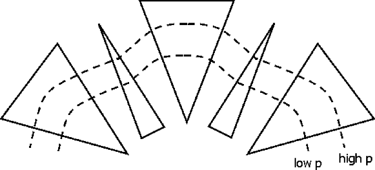
Figure 2 gives a very conceptual illustration of the basic idea of FFAGs. It can be seen that the alternating sign of the bending field results in net bending in the direction of the stronger dipoles a provides the scalloped beam trajectories that are characteristic of FFAGs. Further out trajectories see a progressively stronger average bending field and so are appropriate for transporting larger momenta in proportion to the average magnetic field strength.
FFAGs were first considered back in the 1950’s FFAGhistory but, presumably, were not developed further at that time because the simpler alternative of slowly ramping synchrotrons was adequate for the acceleration of stable particles. Impressively, FFAG lattices have now been designed that transport as much as factors of 5 to 10 in muon momentum, although such extreme designs require very large apertures and the peak magnetic fields are several times the average bending field. Some initial design studies for more practical FFAG lattices are presented elsewhere in these proceedings Garren ; Dejan .
Perhaps the biggest technical problem with all FFAG scenarios is the difficulty in maintaining turn-by-turn an appropriate phase relationship with the rf acceleration, since the path lengths of the muon orbits within the FFAG lattice get progressively larger with increasing energy – as is conceptually illustrated in figure 2. It is a nice feature of many-TeV colliders that these problems become progressively less at higher energies because the increasing revolution period through the arcs gives more time for adjustments between passes through the linac.
III.3 Rf Acceleration and Decay Losses
The amount of radio-frequency (rf) acceleration per turn will be determined by a trade-off between minimizing the expense and the tunnel length occupied by rf (favors less rf) and minimizing the number of turns and the decay losses (favors more rf).
A formula relating the decay losses to the rf and recirculator parameters can be derived directly from the decay equation for the change in the number of muons, , with distance, :
| (7) |
where is the speed of light, the scaled muon velocity is essentially unity for the muon energies under consideration, , is the conventional relativistic gamma factor and the muon mass and its lifetime, , are such that .
It follows easily that muon decay losses lead to ratios of initial to final bunch populations, , that are related to the recirculator tunnel lengths in units of kilometers, , the number of GeV per turn of rf acceleration, , and the ratio of final to initial energies in the recirculator, , through
| (8) |
where is the index for the of N recirculators. Equation 8 has made the approximation of averaging the acceleration to an assumed constant gradient over the length of the recirculator rather than the real situation where it will be concentrated in one or more rf linacs placed around the recirculator. This should introduce only small fractional errors in the calculated particle losses for the parameters given in table 2.
III.4 Optimization of the Straw-man Acceleration Scenario
The straw-man acceleration scenario presented in table 2 starts at 500 GeV, working on the assumption that the acceleration to this energy range has already been developed and used for a previous TeV-scale collider. The acceleration scenario for the TeV collider (set A) then needs to provide exactly one decade of energy gain, accelerating the beams from 0.5 TeV up to their collision energy of 5 TeV. It economizes on expensive rf acceleration by utilizing only a relatively modest 50 GV of rf cavities.
The TeV collider scenarios start with the TeV acceleration scenario and add a further decade of acceleration to raise the beam energies to 50 TeV. A further 250 GV of rf cavities are utilized, which is, for example, much less rf than is required for the next generation of colliders and so should be easily compatible with the budget constraints on a 100 TeV collider.
In more detail, it can be seen from table 2 that the recirculating accelerator to 50 TeV is essentially a scaled copy of that to 5 TeV. Both recirculators use 5 rings of FFAG arcs and the fractional momentum increment in each of the 5 rings is the same between the first and second recirculator. As one difference, the average bending fields, , in the second recirculator are assumed to be a factor of 1.5 times higher than in the first.
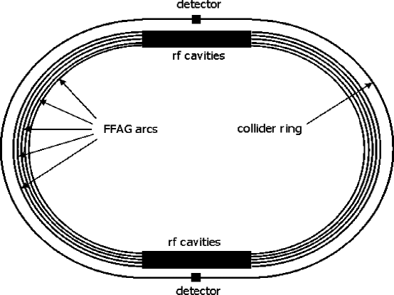
Figure 1 is a schematic diagram for a possible layout of either of the two recirculators. As a specific suggestion of this layout, it assumes the 5 FFAG rings to be housed in the same tunnel. Further, this tunnel is assumed to be the collider tunnel, i.e., the 5+5 TeV collider for the first recirculator and the 50+50 TeV collider for the second.
The obvious motivation for the layout of figure 1 is to minimize the complexity and tunnel expense of the scenario. However, requiring all 5 FFAG rings in a recirculator to have the same radius as the collider ring has the obvious consequences of fixing the FFAG ring radii and of constraining the average bending magnetic fields in each ring according to the ranges of transported momenta in that ring. Table 2 gives a specific scenario for doing this.
The design of the later FFAG rings in each recirculator is clearly more constrained than those for the earlier rings because the average bending field must be closer to the (assumed high) average bending field of the collider ring. This is dealt with in table 2 by constraining the momentum swing to become progressively smaller for the later rings in the recirculators. Assumed energy ranges covered by the arcs range from a factor of 2.5 increase – for the lowest energy arcs in each recirculator – down to 10% energy gain for the highest energy arcs in each recirculator. These are really no more than guesses since, for example, the magnet apertures and ratios of peak-to-average magnetic fields required for this scenario are unknown.
Assumed average gradients for superconducting rf of 25 MV/m, as is assumed for the proposed TESLA collider, correspond to total rf lengths of 2 km (10 km) for the 10 TeV (100 TeV) colliders, which is 13.3% (10.0%) of the collider ring circumference. The example schematic layout of figure 1 shows the rf to be split equally between the two straight sections of tunnel on the opposing sides of the “race-track” collider ring, although this choice was somewhat arbitrary.
Decay losses were calculated according to equation 8. Non-decay losses were neglected. Synchrotron radiation energy losses – which range up to about 10% per turn at 50 TeV – have been included in a simple approximate manner. Table 2 shows the overall decay losses to be acceptably low, at 10.5% and 13.9% respectively, for each of the two decades of energy gain.
Having detailed the scenario, it should again be emphasized that the overall scenario, together with its specific choices and assumptions, was intended to do no more than provide the seed for more credible design studies from the accelerator physicists attending this workshop. Nothing but the qualitative assumptions of the scenario should be considered at all, and even these only at the reader’s discretion. Of course, none of the specific numerical assumptions should be taken at all seriously, beyond perhaps obtaining a rough qualitative feel for such parameters as the amount of rf acceleration required and the magnitudes for the fractional decay losses.
Bearing the preceding paragraph in mind, we conclude this section by again referring the reader to the vastly more competent and detailed acceleration studies that emerged from the workshop: the overall acceleration scenarios of reference Berg and the FFAG design studies in references Garren and Dejan .
IV Assessment of the Muon Collider Parameter Sets at HEMC’99
| parameter set | A | B | C |
|---|---|---|---|
| center of mass energy, | 10 TeV | 100 TeV | 100 TeV |
| additional description | evol. extrap. | evol. extrap. | ultracold beam, etc. |
| Luminosity for Physics: | excellent | fair | excellent |
| Technology: | |||
| acceleration | probably OK | OK | OK |
| detector backgrounds | probably OK | probably OK | probably OK |
| beam cooling | probably OK | probably OK | problematic |
| synch. radiation | probably OK | borderline | NOT FEASIBLE |
| final focus | challenging | problematic | problematic |
| overall technology: | challenging | problematic | NOT FEASIBLE |
| Cost: | challenging | problematic | problematic |
| neutrino rad./siting | dedicated new site | same site | same site |
| OVERALL | challenging | problematic | NOT FEASIBLE |
This section reviews the studies and assessments at HEMC’99 of the collider ring and acceleration parameter sets of tables 1 and 2. It will concentrate on the muon collider design issues arising out of the parameter sets. The reader is also referred to the summary paper by Willis Willis for a more general overview of the findings of the workshop.
Table 3 summarizes the status of the acceleration and collider parameter sets after review at the workshop. As an important piece of contextual information, the assessment of parameter set A (10 TeV), assumes that a TeV-scale muon collider has already been built and successfully operated and the parameter set in each successive column assumes that the collider of the preceding column has already been built.
The following subsections have been grouped according to subject areas that follow fairly closely, but not exactly, the rows of table 3: on luminosity, acceleration, detectors, cooling, synchrotron radiation, final focus design and beam instabilities. A more general outlook and list of conclusions based on these observations will be deferred to the final section, section V.
IV.1 Assessment of Luminosities for Physics
The luminosity requirements for colliders are discussed in some detail elsewhere in these proceedings hemc99intro . Ideally, collider luminosities should rise as and it is seen that, indeed, the luminosities for all three parameter sets in table 1 are higher than for any existing or (to the author’s knowledge) other proposed collider.
Both parameter sets A and C have excellent luminosities, even considering their high energies, while the luminosity of parameter set B was still considered to be “fair” for a 100 TeV lepton collider. (See reference hemc99intro for further discussion.)
IV.2 Assessment of the Acceleration Scenario
Studies at HEMC’99 focused more on the collider ring parameter sets of table 1 than on the acceleration scenario of table 2. The acceleration scenario was considered critical mostly to the extent that it would be expected to be the biggest single component of the overall cost of the collider. Unfortunately, the cost of the FFAG magnets was not able to be explicitly addressed in any detail due to the newness and developing nature of FFAG scenarios Garren ; Dejan for muon colliders. A rather indirect source for some optimism on the acceleration costs could come from any assumed correlation with some relatively favorable cost estimates for the collider ring magnets, by Harrison Harrison , who roughly assessed the cost for the collider magnets for the 10 TeV scenario (set A) to be perhaps of order 400 million dollars.
Technically, muon acceleration tends to get easier at higher energies due to the increasing muon lifetime, smaller beam sizes and lower circulation frequencies in recirculating linacs. Hence, the technical feasibility of acceleration up to the energies in the table is automatically established to a large extent by the assumed previous success of the acceleration at a TeV-scale collider. As a minor caveat to this, Harrison pointed out the increased load due to synchrotron radiation in the FFAGs. However, the collider ring magnets will need to handle the synchrotron radiation load for many times more turns than the FFAG arcs, so even this technical difficulty is concentrated more in the collider ring than the accelerating lattice.
Berg Berg pointed out that slightly increased technical difficulties might instead be expected for the low energy end of the acceleration for parameter sets A and, especially, B. This could result from the higher specified values for the longitudinal emittance in the many-TeV parameter sets: table 1 shows the longitudinal emittances for these parameter sets to be, respectively, similar to, and about twice as large as, the longitudinal emittance for the 3 TeV parameter set of reference status .
IV.3 Detector Backgrounds
All muon collider detectors face challenging backgrounds resulting from the electron daughters of decaying muons near the interaction point. However, the amount of electromagnetic “junk” entering the detector is relatively independent of the collider energy since the power density of deposited electromagnetic energy depends primarily on the beam current rather than the beam energy. (For confirmation of this statement, see the values in the “power density into magnet liner” row of table 1.) Hence, such backgrounds are expected to be manageable for these many-TeV parameter sets under the stated assumption that the problem has already been solved at TeV-scale collider detectors. (A specific strategy for handling these backgrounds that was developed at the workshop is described in reference Rehak of these proceedings.)
Muons entering the side of the detector, either from beam halo or Bethe-Heitler pair production, are the one background that is expected to evolve markedly with energy. As muons become more relativistic they become less and less like minimum-ionizing particles and deposit larger amounts of energy “catastrophically” in, mainly, electromagnetic showers. This issue was not addressed at the workshop and it deserves further study.
IV.4 Beam Cooling
Parameter sets A and B assume only evolutionary improvements in the ionization cooling performance over that assumed (but far from demonstrated status !) for TeV-scale colliders so, by definition, the beam cooling should probably be OK if following on from the TeV-scale collider. Parameter set C is very different, assuming that some form of exotic cooling will be able to increase the phase space density of the muon beams by three orders of magnitude from that assumed for parameter set B.
Such ultra-cold muon beams are still looking plausible but have not yet progressed beyond that. The most promising of the exotic cooling methods is optical stochastic cooling Zholents . This method clearly has formidable technical challenges but no obvious show-stoppers. Other, very low energy, cooling methods were also presented at the workshop Lebrun ; Nagamine . There is some concern that any cooling method using non-relativistic muons (i.e. with scaled velocity ) may well not be feasible for preparing the high-charge muon bunches needed for colliders, due to space charge limitations.
It is noted that parameter set C provides a specific example of a general feature for ultra-cold muon beams. Since the collisions at many-TeV colliders would normally be tune-shift limited anyway, it is likely that improved cooling would also require ip compensation to substantially benefit the luminosity. We now discuss yet another barrier to the use of ultra-cold beams, at least at very high energies, from synchrotron radiation.
IV.5 Synchrotron Radiation
It has already been noted that the synchrotron radiation power in the 100 TeV colliders is already comparable to the beam power. During the workshop, Telnov Telnovsynch raised what might possibly be a stronger constraint from synchrotron radiation on the energy reach of circular muon colliders, namely, the quantum nature of synchrotron radiation may lead to heating, rather than damping, of the horizontal beam emittance if the beam energy is high enough and the emittance is already very small.
Telnov’s observation clearly spells the end of parameter set C, with its ultra-cold beam at TeV. The other parameter set at 100 TeV (set B) is also borderline, with an initial horizontal emittance that is larger by a factor of five Telnovsynch than the equilibrium emittance due to this effect, as calculated by Telnov using a simple approximate model.
The most likely possible loop-hole for parameter set B is that the heating effect is reduced for a very strongly focusing collider lattice. More specifically, Telnov’s equation 2 shows the equilibrium emittance to be proportional to the average of the “H-function” around the collider ring, where
| (9) |
for the standard Courant-Snyder parameter and the collider ring’s radius. (Stronger focusing corresponds to smaller values around the ring.)
To consider adjustments to parameter set B, equation 9 suggests that 100 TeV colliders with the emittances expected from ionization cooling still look to be feasible by increasing the ring radius, , by, for example, a factor of two. This would lower both the equilibrium emittance by a factor of four and the radiated energy per turn by a factor of two, which is substantial compensation for halving the number of collisions per bunch.
A much more dramatic approach to beating the energy limits from synchrotron radiation has come from Zimmermann Zimmermann , in the form of single pass linear colliders. Example parameter sets are included in Zimmermann’s paper, and are commented on in more detail elsewhere in these proceedings hemc99intro .
IV.6 Final Focus Design
The final focus design extrapolations discussed in section II seemed to work well for the 10 TeV parameter set A. A magnet layout for the final focus from Johnstone Carol closely reproduced the predicted in table 1. Further, the lattice design experts at the workshop seemed to appreciate the extremely challenging nature of the 10 TeV final focus parameters without everybody actually condemning them as being clearly unrealistic, i.e., an appropriate level of difficulty for a workshop of this nature! See reference Zimmermann for more detailed studies and comments.
The 100 TeV parameter sets were less fortunate. Even the “evolutionary” parameter set B was immediately dismissed by the lattice experts as being incompatible with any final focus lattice designs using conventional magnets. It will be very useful to get further feedback on what exactly broke down in the simplistic energy extrapolation that was described in section II.1. Hopefully, such feedback can then be used to obtain a better parameterization of the energy evolution in the final focus parameters. A more realistic and better established parameterization could then be used to predict the luminosity scaling with energy that might be expected using conventional final focus technologies.
Finally, two exotic final focus options were discussed that might go beyond conventional magnet designs: “dynamic focusing” (using auxiliary beams to focus the colliding beams) and plasma focusing. Discouragingly, both options looked much less plausible than when considered for single pass colliders, due to both the need for multiple passes and the larger bunch currents assumed for collider parameters. Also disappointing are the obstacles to beam compensation at collision (as was assumed in parameter set C), which call into question the possibility of being able to do this – see reference Telnovcomp for discussion on this topic.
IV.7 Beam Instabilities in the Collider Ring
Papers by Keil Keil and Zimmermann Zimmermann provide studies on beam instabilities. Keil provides a systematic assessment of the classes of instabilities, including parameter comparisons with the LHC collider ring. Zimmermann’s tracking studies demonstrated that even circulating the beams for a single turn should not be taken for granted, let alone for of order 1000 turns over the lifetime of the muons.
As a connection to the physics capabilities of the collider ring that needs to be borne in mind, the common assumption status of collider rings that are isochronous is disfavored for retaining the beam polarization. (See also reference Heusch for a discussion on the importance of polarization.) As a rough hand-waving explanation, the rate of polarization precession while circulating in the collider ring is proportional to the muon’s energy. It is intuitively clear that the polarization will decay away more slowly if the energies of all the particles are allowed to slosh around the beam average energy – sometimes gaining in polarization precession (higher energy) over the bunch average precession and sometimes losing (lower energy than the bunch average). This is what happens in a collider ring with longitudinal focusing as opposed to isochronous rings. The same argument also favors small beam energy spreads.
V Outlook and Conclusions
The preceding section has reviewed the insights from HEMC’99 on the parameter sets of tables 1 and 2. More generally than this, HEMC’99 has provided the first speculative insights into (i) the ultimate physics potential for future colliders at the high energy frontier and (ii) the potential challenges to reaching very high energies with muon colliders. A personal interpretation of the workshop’s findings through the energy decades is:
-
•
muon colliders to the TeV scale: (added for completeness – these energies were not discussed in detail at the workshop) beam cooling is the dominant technical challenge. Other major challenges are the final focus region, backgrounds in the detector, cost-efficient acceleration and beam stability throughout the cooling, acceleration and storage in the collider ring. Neutrino radiation will impose significant design constraints and the beam currents may be well below those for the straw-man parameters in reference status (i.e. muons/sign/year in collision).
-
•
to advance to the 10 TeV scale: neutrino radiation will probably dictate a new site. The final focus region of the collider and magnet cost reduction for acceleration may be the other major technical design issues.
-
•
to advance to the 100 TeV scale: major breakthroughs are needed in magnet costs and in the final focus region.
-
•
to advance to the 1 PeV scale and beyond: this is not absolutely ruled out in the far distant future using a linac and many technological breakthroughs, as illustrated by the parameter set in reference Zimmermann and discussed further in reference hemc99intro .
It would certainly be very valuable to follow up on the understandings gained at this workshop. As a small first step, modified parameter sets for many-TeV muon colliders are being generated epac2000 that take into account the insights gained at HEMC’99. As a refinement to make interpolations easier, a parameter set at the intermediate center-of-mass energy of 30 TeV will be included.
More substantially, there is need for a new study and workshop. Preferably, this should include all three of the main accelerator technologies – pp, and colliders. This is motivated hemc99intro both for a more coherent understanding of the future of experimental high energy physics and in recognition that the three accelerator technologies are deeply intertwined. Planning is underway for such a study to take place in the Summer and Fall of 2001.
References
-
(1)
B.J. King,
Neutrino Radiation Challenges and Proposed Solutions for
Many-TeV Muon Colliders, these proceedings.
Also available from
http://pubweb.bnl.gov/people/bking/heshop/hemc_papers.html. - (2) B.J. King, Discussion on Muon Collider Parameters at Center of Mass Energies from 0.1 TeV to 100 TeV, Proc. EPAC’98, BNL–65716. available from LANL preprint archive as physics/9908016.
- (3) B.J. King, Muon Colliders from 10 TeV to 100 TeV, Proc. PAC’99, New York, 1999, pp. 3038-40, available from LANL preprint archive as physics/9908018.
- (4) B.J. King, Muon Colliders: New Prospects for Precision Physics and the High Energy Frontier, Proc. Second Latin American Symposium on High Energy Physics, San Juan, Puerto Rico, 8-11 April, 1998, available from LANL preprint archive as hep-ex/9908041.
-
(5)
B.J. King,
Prospects for Colliders and Collider Physics to the
1 PeV Energy Scale,
these proceedings.
Also available from
http://pubweb.bnl.gov/people/bking/heshop/hemc_papers.html. - (6) The Muon Collider Collaboration, Collider: A Feasibility Study, BNL-52503, Fermilab-Conf-96/092, LBNL-38946, July 1996.
-
(7)
Valery Telnov,
Limit on Horizontal Emittance in High Energy Muon Colliders
due to Synchrotron Radiation,
these proceedings. Also available from
http://pubweb.bnl.gov/people/bking/heshop/hemc_papers.html. - (8) F. Zimmermann, Final Focus Challenges for Muon Colliders at Highest Energies, ibid.
- (9) The Muon Collider Collaboration, Status of Muon Collider Research and Development and Future Plans, Phys. Rev. ST Accel. Beams, 3 August, 1999.
-
(10)
J. Scott Berg,
Acceleration for a High Energy Muon Collider,
these proceedings. Also available from
http://pubweb.bnl.gov/people/bking/heshop/hemc_papers.html. - (11) K.R. Symon, The FFAG Synchrotron – MARK 1, MURA-KRS-6, November 12, 1954, pp. 1-19.
-
(12)
Al Garren,
A Scaling Radial-Sector FFAG Lattice for a Muon Accelerator,
these proceedings. Also available from
http://pubweb.bnl.gov/people/bking/heshop/hemc_papers.html. - (13) Dejan Trbojevic, Ernest D. Courant and Al Garren, FFAG Lattice Without Opposite Bends, ibid.
- (14) Bill Willis, Muon Collider Workshop Summary, ibid.
-
(15)
Mike Harrison,
Magnet Challenges: Technology and Affordability,
oral presentation at this workshop. Transparency copies can
be viewed at
http://pubweb.bnl.gov/people/bking/heshop/hemc_papers.html. -
(16)
P. Rehak et al.,
Detector Challenges for Colliders in the 10-100 TeV
Range,
these proceedings. Also available from
http://pubweb.bnl.gov/people/bking/heshop/hemc_papers.html. -
(17)
A.A. Zholents,
The Potential for an Optical Stochastic Cooling After-Burner,
oral presentation at this workshop. Transparency copies can
be viewed at
http://pubweb.bnl.gov/people/bking/heshop/hemc_papers.html. -
(18)
Paul Lebrun,
Comments on Frictional Cooling and the Zero Energy Options
for Cooling Intense Muon Beams,
these proceedings. Also available from
http://pubweb.bnl.gov/people/bking/heshop/hemc_papers.html. - (19) Kanetada Nagamine, Very Low-Energy Cooling Possibilities Towards Muon Colliders and Neutrino Factory, ibid.
-
(20)
Carol Johnstone,
Collider Ring Lattices,
oral presentation at this workshop. Transparency copies can
be viewed at
http://pubweb.bnl.gov/people/bking/heshop/hemc_papers.html. -
(21)
Valery Telnov,
Some Problems in Plasma Suppression of Beam-Beam Interactions
at Muon Colliders,
these proceedings. Also available from
http://pubweb.bnl.gov/people/bking/heshop/hemc_papers.html. - (22) Eberhard Keil, Collective Single-Beam Effects, ibid.
- (23) Clemens A. Heusch, Physics Opportunities with a High-Energy Collider of Same-Sign Muons, ibid.
- (24) B.J. King, parameters and paper in preparation for the EPAC 2000 conference.