IIT-HEP-99/3
Fermilab-Conf-00/019
physics/0001037
Muon Collider/Neutrino Factory: Status and Prospects
Abstract
During the 1990s an international collaboration has been studying the possibility of constructing and operating a high-energy high-luminosity collider. Such a machine could be the approach of choice to extend our discovery reach beyond that of the LHC. More recently, a growing collaboration is exploring the potential of a stored-muon-beam “neutrino factory” to elucidate neutrino oscillations. A neutrino factory could be an attractive stepping-stone to a muon collider. Its construction, possibly feasible within the coming decade, could have substantial impact on neutrino physics.
1 Introduction
The Neutrino Factory and Muon Collider Collaboration (NFMCC) [1] is engaged in an international R&D project to establish the feasibility of a high-energy collider and a stored-muon-beam “neutrino factory.” As a heavy lepton, the muon offers important advantages over the electron for use in a high-energy collider:
-
1.
Radiative processes are highly suppressed, allowing use of recycling accelerators. This reduces the size and cost of the complex. It also allows use of a storage ring, increasing luminosity by a factor over a one-pass collider.
-
2.
In the Standard Model and many of its extensions, use of a heavy lepton increases the cross section for -channel Higgs production by a factor , opening a unique avenue for studying the dynamics of electroweak symmetry breaking [2]. More generally, a sensitivity advantage may be expected in any model that seeks to explain mass generation [3].
-
3.
Beam-beam interactions make high luminosity harder to achieve as the energy of an linear collider is increased, an effect that is negligible for muon colliders [4].
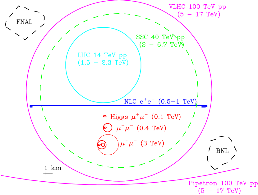
The small size anticipated for a muon collider is indicated in Fig. 1, which compares various proposed future accelerators. Unlike other proposals, muon colliders up to TeV fit comfortably on existing Laboratory sites. Beyond this energy neutrino-induced radiation (produced by neutrino interactions in surface rock), which increases as , starts to become a significant hazard, and new ideas or sites where the neutrinos break ground in uninhabited areas would be required. A muon collider facility can provide many ancillary benefits (physics “spinoffs”) and can be staged to provide interesting physics opportunities even before a high-energy collider is completed. These include experiments [5] with intense meson and muon beams produced using the high-flux ( protons/year) proton source, as well as neutrino beams of unprecedented intensity and quality, discussed below in Sec. 7.
Ref. [6] is a comprehensive summary of the status of muon collider research as of 1 year ago. While stored muon beams have been discussed since 1960 [7], and muon colliders since 1968 [8], only in recent years has a practical approach to the realization of a collider been devised. The key concept that may allow a muon collider to become a reality is ionization cooling [9, 10, 11]. Muons may be copiously produced using collisions of multi-GeV protons with a target to produce pions, which then decay in a focusing “capture channel.” However, those muons occupy a large emittance (phase-space volume) and are unsuitable for injection directly into an accelerator. Muon-beam cooling is needed to reduce the emittance by a sufficient factor but must be carried out in a time short compared to the s muon lifetime. While other beam-cooling methods are too slow, as discussed below, simulations show that ionization cooling can meet these requirements.
2 Proton Source, Targetry, and Capture
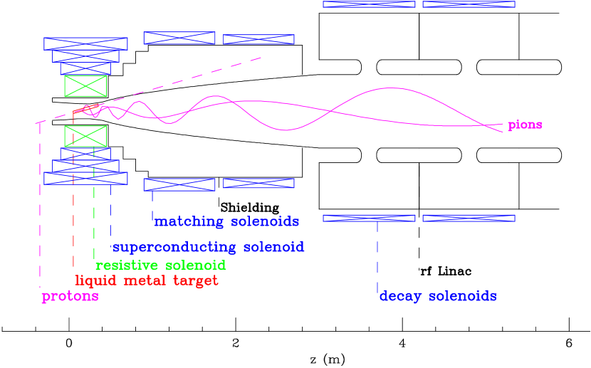
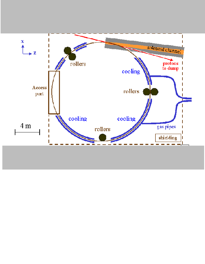
Muon-collider luminosity estimates (see Table 1) have been made under the assumption that a 4 MW proton beam may safely strike a target representing 2–3 hadronic interaction lengths, which is tilted at a 100–150 mr angle with respect to the solenoidal focusing field (see Fig. 2). Design studies are ongoing to demonstrate this in detail, and BNL-E951 at the AGS will test this experimentally within the next few years [12]. Ideas being explored include a liquid-metal jet target (Fig. 2) and a “bandsaw” target (Fig. 3). In neutrino-factory scenarios the beam power requirement is eased to 1 MW, making a graphite target also a possibility. About 10% of the beam energy is dissipated in the target. A target with comparable dissipation is being designed for the Spallation Neutron Source at Oak Ridge National Laboratory [13]. The required 4 MW proton source, while beyond existing capability, is the subject of ongoing design studies at Brookhaven [14] and Fermilab [15] and is comparable in many respects to machines proposed for spallation neutron sources [16]. For efficient capture of the produced low-energy pions, the target is located within a 20 T solenoidal magnetic field to be produced using a superconducting solenoid with a water-cooled copper-coil insert (Fig. 2). The captured pions and their decay muons proceed through a solenoidal field that decreases adiabatically to 1.25 T. Simulations show that 0.6 pions/proton are captured in such a channel for proton energy in the range 16–24 GeV.
The resulting muon bunches, while very intense, feature a large energy spread, which must be decreased for acceptance into a cooling channel. This can be accomplished via radio-frequency (RF) “phase rotation,” by which the energy of the low-energy muons is raised and that of the high-energy muons lowered. This brings a substantial fraction (60%) of the muons into a narrow energy range at the expense of increasing the bunch length (Fig. 4). The large transverse size of the beam at this point necessitates low-frequency (30–60 MHz) RF cavities. An alternative under investigation is use of an induction linac. If the phase-rotation accelerating gradient is sufficiently high (4–5 MV/m), a significant portion of the pions can be phase-rotated before they decay, allowing muon polarization as high as 50%. Otherwise the polarization is naturally 20% [17]. Muon polarization can be exploited in a variety of physics studies [6] as well as in a neutrino factory [18]. It can also provide a fill-to-fill relative calibration of the beam energy [19] (needed e.g. to measure the width of the Higgs).

3 Ionization Cooling
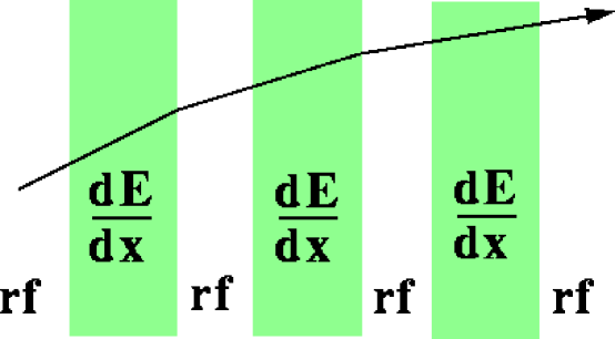
The goal of beam cooling is to reduce the normalized six-dimensional emittance of the beam. The significance of emittance for accelerator design is that it places limits on how tightly the beam can be focused and determines the apertures necessary to transport and accelerate it without losses. A muon beam can be cooled by passing it alternately through material, in which ionization energy loss reduces both the transverse and longitudinal momentum components, and RF accelerating cavities, in which the lost longitudinal momentum is restored (Fig. 5). This process reduces the transverse momentum components relative to the longitudinal one (“transverse cooling”).
Before summarizing the theory of ionization cooling we must first define emittance more carefully.
3.1 Emittance
Emittance can be defined in terms of the vector of canonical variables describing each muon, which can be chosen as . In the absence of correlations among these variables, the six-dimensional volume of the beam in phase space can be represented by , where designates the r.m.s. width of the distribution in the th variable. More generally, the normalized six-dimensional emittance is given by , where is the covariance matrix of , is the mass of of the muon, and is the speed of light. If the off-diagonal (correlation) terms of are negligible, the emittance can be approximated as , where and so forth, or in a cylindrically-symmetric system such as we consider below, , where () is the normalized transverse (longitudinal) emittance.
By Liouville’s theorem, normalized emittance is conserved in linear beam transport and acceleration. Beam cooling thus requires a “violation” of Liouville’s theorem, which is possible by means of dissipative forces such as ionization energy loss [10].
3.2 Ionization-cooling theory
Ionization cooling is approximately described by the following equation [11, 20]:
| (1) |
where is the path length, the muon energy, the radiation length of the absorber medium, , and is the betatron function of the beam (inversely proportional to the square of the beam divergence).
In Eq. 1 we see, in addition to the transverse cooling term, a transverse heating term due to multiple Coulomb scattering of the muons in the absorber. Since cooling ceases once the heating and cooling terms are equal, Eq. 1 implies an equilibrium emittance, which in principle (neglecting other limiting efects) would be reached asymptotically were the cooling channel continued indefinitely. Since the heating term is proportional to and inversely proportional to the radiation length of the absorber medium, the goal of achieving as small an equilibrium emittance as possible requires us to locate the absorber only in low- regions and to use a medium with the longest possible radiation length, namely hydrogen. To achieve low , we want the strongest possible focusing elements. We are thus led to superconducting solenoids filled with liquid hydrogen as possibly the optimal solution.111However, lithium lenses might give an even lower equilibrium emittance than solenoids with liquid hydrogen, since stronger focusing fields may be feasible with liquid-lithium lenses than with magnets, and this may overcome the radiation-length advantage of hydrogen.
Below the ionization minimum, energy loss increases approximately as , while Coulomb scattering increases only as [22]. Ionization cooling thus favors low momenta, despite the relativistic increase in muon lifetime with momentum. In fact, Eq. 1 implies that the equilibrium emittance scales approximately as . Most simulations of muon cooling are now being done at MeV/. Still lower momenta could in principle be better but are difficult to transport in practice due to larger beam divergences.
3.3 Cooling channel designs
In the “alternating-solenoid” cooling channel [23] the muon beam is kept focused by a series of superconducting solenoids alternating in magnetic-field direction (Fig. 6). As the field alternates, its magnitude must of course pass through zero; at these points is necessarily large. Here solenoids with large inner bore are suitable, allowing insertion of RF cavities. In between are regions of low , corresponding to maxima of the magnetic field, where the liquid-hydrogen absorbers are located. (The field directions alternate so that canonical angular momentum [24], which builds up within each absorber as the muon beam loses mechanical angular momentum, cancels rather than building up.) Another type of arrangement (dubbed “FoFo”) is also under study, in which solenoid fringe-field focusing is employed. This allows lower values for a given field strength than in the alternating-solenoid arrangement. In the FoFo channel the low- regions (and the absorbers) are thus at low field and the RF cavities at high field.
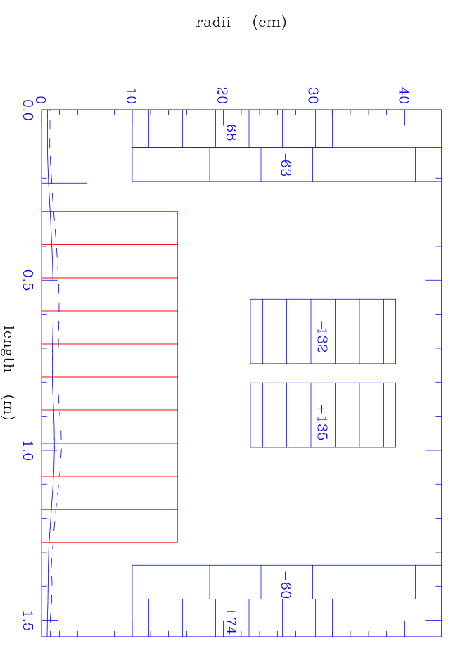

Both the FoFo and alternating-solenoid cooling channels feature liquid-hydrogen absorbers in which a substantial amount of power is dissipated by the muon beam. In a typical case, muons per bunch at a 15 Hz repetition rate deposit a few hundred watts in each absorber. This is within the range of operation of high-power liquid-hydrogen targets that have been used in the past [25] or proposed for future experiments [26]. Careful attention must be paid to the design of these absorbers, for reasons both of safety and of performance. For example, the windows must be made of low- material and kept as thin as possible in order not to degrade the cooling performance by causing excessive multiple scattering. Aluminum alloy appears to be an acceptable solution.
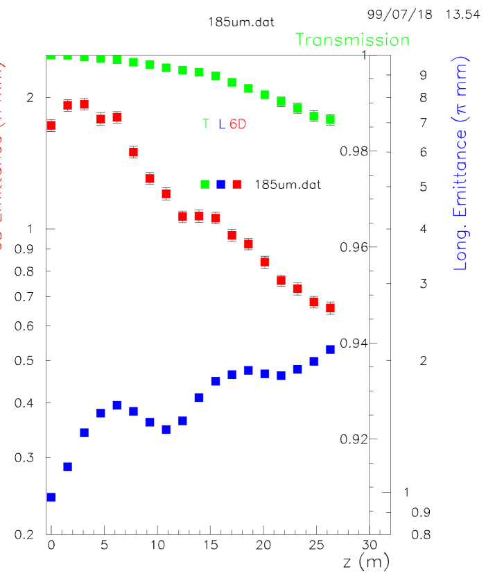
As an example of the performance that can be achieved in such a cooling channel, Fig. 7 shows as a function of distance the six-dimensional and longitudinal beam emittances as well as the relative beam intensity in a simulated alternating-solenoid channel using 15 T solenoids and 805 MHz RF cavities. These cooling-channel parameters are representative of a late stage of cooling for a muon collider and were chosen for initial detailed studies in order to demonstrate a solution in a technically-challenging regime. The six-dimensional emittance is reduced by a factor of 3 in 26 m, with less than 2% non-decay beam loss.
Eq. 1 implies a natural scaling of the cooling-channel components as the beam becomes progressively cooler: to maintain the cooling rate as equilibrium is approached, must be periodically decreased to establish a new, smaller, equilibrium emittance. This means the focusing fields must become stronger. How small a can be achieved in an alternating-solenoid channel has not yet been definitively determined, but 20 T seems a practical upper limit to superconducting-solenoid field strength [27], and perhaps 30 T in a superconducting/copper hybrid design. To continue transverse cooling beyond the practical limit for the alternating-solenoid channel, liquid-lithium lenses or FoFo-type channels may be solutions. In a scenario sketched by Palmer [28, 6] a factor in six-dimensional emittance is achieved in a distance of 500 m using a series of 25 alternating-solenoid channels followed by three lithium-lens stages, with each stage contributing a factor of about 2. This cooling factor is sufficient to permit the collider luminosities of Table 1.
3.4 Emittance exchange
As the muon beam passes through the transverse-cooling channel the longitudinal emittance grows. This arises from four effects:
-
1.
Working below the ionization minimum, there is positive feedback, since as the muons lose momentum their energy-loss rate increases.
-
2.
The beam energy spread increases in the absorber due to energy-loss straggling.
-
3.
The bunch tends to drift apart because slow muons take longer to traverse the channnel than fast muons.
-
4.
The bunch tends to drift apart because muons at large transverse amplitude follow helical trajectories of greater path length than muons at small transverse amplitude.
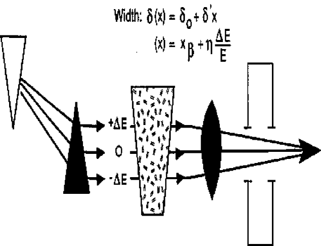
Eventually, significant beam losses begin to occur (see Fig. 7) as muons drift outside the stable RF bucket. At this point longitudinal emittance must be exchanged for transverse emittance. Such emittance exchange may be accomplished by placing wedge-shaped absorbers at a point of momentum dispersion in the beam transport lattice (Fig. 8). With high-momentum muons passing through a greater thickness of absorber than low-energy muons, the beam energy spread is reduced, at the expense of an increase in transverse beam size. While solutions have been devised on paper, detailed simulations so far have shown that a concrete realization of this idea is challenging, and work is ongoing to find a practical solution.
3.5 RF Development
Rapid muon cooling requires development of high-gradient RF cavities (e.g., 36 MV/m at 805 MHz) with suitable high-power drive systems. A novel feature of muon acceleration is the possibility of using “pillbox” cavities, closed at each end by low-mass metal windows, to increase the uniformity of the electric field within the cavity and lower the power requirements. These developments are in progress, with 805 MHz [29] and 175–200 MHz designs now under development and planned for testing over the next few years at BNL, FNAL, and LBNL. Alternative gridded and windowless designs are also in progress, as well as power-source design studies.
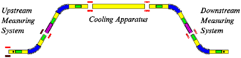
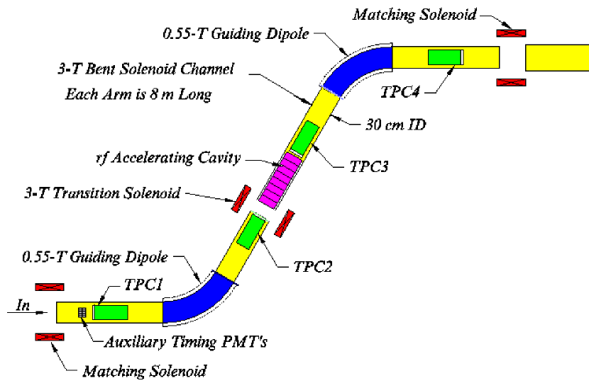
3.6 Muon Cooling Experiment
While the physics underlying ionization cooling is reasonably well understood, ionization cooling has yet to be demonstrated in practice. To demonstrate feasibility and establish performance, a muon cooling experiment (MUCOOL) [30] has been proposed to Fermilab (Fig. 9). With the increasing interest in the possibility of a muon-storage-ring neutrino factory, over the last year the activities of the NFMCC have undergone a change of emphasis, and the focus of the proposed experiment is now turning from the late stages of cooling to the initial stages. We now envisage a cooling test facility that will be staged so as to demonstrate initial-stage cooling (such as will be needed for a neutrino factory) first, with tests of late cooling stages (needed for a muon collider) coming later. The lower RF frequency used in early cooling stages relaxes requirements for timing-measurement resolution, thus simpler measurement approaches than indicated in Fig. 9 are now envisaged.
4 Acceleration
Rapid acceleration to the collider beam energy is needed to avoid excessive decay losses. This can be accomplished in a series of linacs and “racetrack” recirculating linear accelerators (RLAs) such as have been developed at Jefferson Laboratory. Several scenarios have been considered. As an example [31], linacs at 175 and 350 MHz can be employed to raise the energy of the cooled muon beam to 2 GeV, after which it is accelerated in a first 4-turn RLA to 8 GeV and, in a second, to 30 GeV (a possible storage-ring energy for a neutrino factory). Other scenarios include RLAs with larger numbers of turns, “dogbone-geometry” RLAs [32], and fixed-field alternating-gradient [33] (FFAG) accelerators. At sufficiently high energy (above a few hundred GeV), the muon lifetime becomes long enough that ramped “rapid-accelerating” synchrotrons may be used [34].
5 Collider Scenarios
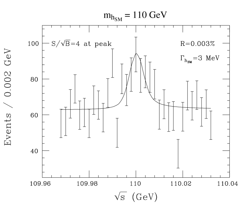
Collider scenarios have been considered at three energies, , 0.4, and 3 TeV (see Table 1). Three variants of the 0.1 TeV (“Higgs Factory”) machine have been worked out, covering a range of momentum spread. While reducing the momentum spread also reduces the luminosity, given the narrow width expected for the Higgs, the event rate and Higgs precision are optimized at the narrowest momentum spread (Fig. 10) [2]. The 0.4 and 3 TeV scenarios are aimed respectively at precision top studies and at searches in a mass regime beyond the reach of the LHC [34].
| C.M. energy (TeV) | 3 | 0.4 | 0.1 | ||
|---|---|---|---|---|---|
| energy (GeV) | 16 | 16 | 16 | ||
| /bunch | |||||
| Bunches/fill | 4 | 4 | 2 | ||
| Rep. rate (Hz) | 15 | 15 | 15 | ||
| power (MW) | 4 | 4 | 4 | ||
| /bunch | |||||
| power (MW) | 28 | 4 | 1 | ||
| Wall power (MW) | 204 | 120 | 81 | ||
| Collider circum. (m) | 6000 | 1000 | 350 | ||
| Avg. bending field (T) | 5.2 | 4.7 | 3 | ||
| r.m.s. (%) | 0.16 | 0.14 | 0.12 | 0.01 | 0.003 |
| 6D () | |||||
| r.m.s. ( mm-mr) | 50 | 50 | 85 | 195 | 290 |
| (cm) | 0.3 | 2.6 | 4.1 | 9.4 | 14.1 |
| (cm) | 0.3 | 2.6 | 4.1 | 9.4 | 14.1 |
| spot (m) | 3.2 | 26 | 86 | 196 | 294 |
| IP (mr) | 1.1 | 1.0 | 2.1 | 2.1 | 2.1 |
| Tune shift | 0.044 | 0.044 | 0.051 | 0.022 | 0.015 |
| (effective) | 785 | 700 | 450 | 450 | 450 |
| Luminosity (cm-2s-1) | |||||
| Higgs/year | |||||
6 Collider Detector
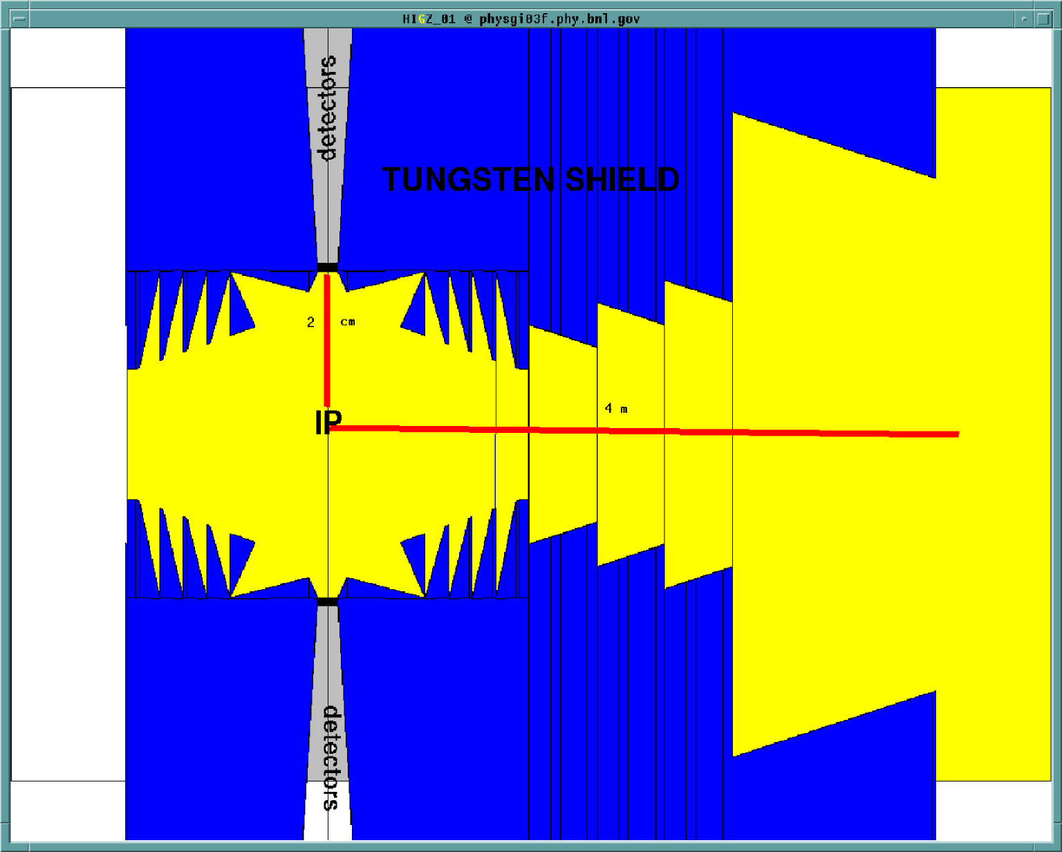
A “strawman” detector has been simulated in Geant [35]. To cope with high background rates from muon decay within the storage ring, pixel detectors are employed near the beamline, and an extensive series of tungsten shields are deployed around the interaction point (Fig. 11). At cm, pixels of dimensions m2 have estimated occupancies below 1%. Pattern recognition still needs study, but these occupancies are encouraging.
7 Neutrino Factory
Recently the possibility of a neutrino factory based on a muon storage ring has received much attention [18, 32, 36, 37, 38]. Such a facility could help unravel the mystery of neutrino mixing by providing neutrino beams of unprecedented intensity, brilliance, and purity. It could also serve as a stepping-stone to a muon collider. A neutrino factory should be easier and cheaper to construct and operate than a muon collider since it requires less cooling and less intense muon bunches. This follows straightforwardly from the fact that collider luminosity, being proportional to the square of the bunch intensity and inversely proportional to the transverse bunch size, requires as small and intense a bunch as possible, while the sensitivity of neutrino experiments is determined simply by the time-integrated flux. In practice this eases the six-dimensional cooling required by a factor , possibly obviating the need for longitudinal-transverse emittance exchange.
A muon collider contains various sources of intense neutrino beams, for example muon decays within the straight sections of the muon accelerators and collider storage ring. As mentioned above, for sufficiently high muon energies these “parasitic” neutrino beams may limit feasibility due to radiation-safety concerns. Such beams could be used to advance both “conventional” neutrino physics (structure functions, , etc.) and neutrino-oscillation studies. At high muon energies the flux of neutrinos is sufficient for useful detection rates on the other side of the earth. Options that have been discussed include beams aimed from Brookhaven, CERN, Fermilab, or KEK to Soudan, SLAC, and Gran Sasso, giving baselines ranging from 700 to 7000 km for neutrino-oscillation searches. Other options are also conceivable, for example use of a new detector at some suitable location.
Unlike a muon collider, in dedicated-neutrino-factory scenarios the muon storage ring would be designed to maximize the fraction of muons decaying in straight sections, leading to an oblong “racetrack” geometry. Other geometries have also been considered, e.g. a triangular or “bowtie-shaped” ring that could aim two neutrino beams simultaneously at two different remote detectors. The bowtie geometry has the virtue of preserving polarization, since it bends equally in both directions.
Table 2 (from Ref. [38]) exemplifies the physics reach that may be achievable assuming muon decays in a storage-ring straight section (1 year of neutrino-factory running) pointed at a 10 kiloton detector. Unlike conventional meson-decay neutrino beams, which are dominantly but with some contamination, neutrino beams from a stored beam are 50% and 50% , while those from are 50% and 50% . The availability of intense high-energy electron-neutrino beams makes possible tau- and muon-neutrino appearance experiments. The use of both muon polarities allows investigation of matter effects in neutrino oscillation. The phenomenology of three-flavor neutrino oscillation (as required if at least two of the three observed effects [39, 40, 41] are conclusively established) is quite complex [37, 38]. No other proposed facility has comparable power to pin down the details of mixing among three neutrino flavors.
| Survival | Appearance | ||||
| sin | sin | sin | |||
| statistical | statistical | 10 Event | 3 sign | ||
| (km) | (GeV) | precision | precision | sensitivity | |
| 732 | 10 | 7.6% | 6.7% | 0.002 | 0.1 |
| 732 | 30 | 14% | 8.9% | 0.0005 | 0.1 |
| 732 | 50 | 17% | 12% | 0.0003 | |
| 2800 | 10 | 1.1% | 2.4% | 0.008 | 0.1 |
| 2800 | 30 | 2.0% | 3.2% | 0.0007 | 0.005 |
| 2800 | 50 | 1.8% | 4.9% | 0.0004 | 0.003 |
| 7332 | 10 | 13% | 6.3% | 0.02 | 0.1 |
| 7332 | 30 | 0.57% | 1.2% | 0.001 | 0.04 |
| 7332 | 50 | 0.64% | 1.4% | 0.002 | 0.02 |
8 Conclusions
The prospect of a high-luminosity collider, once entirely speculative, has by dint of much work and study now been brought into the realm of possibility. While a collider is still a question for the long term (post-2010), ideas (most notably a neutrino factory) spun off from this effort may have a substantial impact on high-energy physics in the coming decade.
References
- [1] For a list of Neutrino Factory and Muon Collider Collaboration members, see http://pubweb.bnl.gov/people/gallardo/collaboration-list.ps.
- [2] V. Barger, M. Berger, J. Gunion, and T. Han, Phys. Rep. 286, 1 (1997).
- [3] See for example R. Casalbuoni et al., Phys. Lett. B 285, 103 (1992); C. T. Hill, Phys. Lett. B 345, 483 (1995); K. Lane and E. Eichten, Phys. Lett. B 352, 382 (1995); K. Lane, Phys. Rev. D 54, 2204 (1996); E. Eichten et al., Phys. Rev. Lett. 80, 5489 (1998).
- [4] R. B. Palmer and J. C. Gallardo, in Proc. XXVIII Int. Conf. on High Energy Physics, Z. Ajduk and A. K. Wroblewski, eds., World Scientific, Singapore (1997), p. 435.
- [5] See Workshop on Physics at the First Muon Collider and Front-End of a Muon Collider, S. Geer and R. Raja, eds., AIP Conf. Proc. 435 (American Institute of Physics, New York, 1998).
- [6] C. Ankenbrandt et al., Phys. Rev. ST Accel. Beams 2, 081001, 1–73 (1999); for a more concise summary see [35].
- [7] See for example G. Charpak, L. M. Lederman, J. C. Sens, A. Zichichi, Nuovo Cim. 17, 288 (1960); A. C. Melissinos (unpublished, 1960; scanned copy at http://www.hep.princeton.edu/mumu/physics/index.html); J. Tinlot and D. Green, UR-875-76 (1965).
- [8] F. F. Tikhonin, JINR Report P2-4120 (Dubna, 1968).
- [9] G. K. O’Neill, Phys. Rev. 102, 1418 (1956); A. A. Kolomensky, Sov. Atomic Energy 19, 1511 (1965); G. I. Budker and A. N. Skrinsky, Sov. Phys. Usp. 21, 277 (1978); D. Neuffer, FNAL Report FN-319 (1979); A. N. Skrinsky and V. V. Parkhomchuk, Sov. J. Nucl. Phys. 12, 223 (1981); D. Neuffer, Part. Acc. 14, 75 (1983); E. A. Perevedentsev and A. N. Skrinsky, in Proc. 12th Int. Conf. on High Energy Accelerators, F. T. Cole and R. Donaldson, eds. (1983), p. 485.
- [10] D. B. Lichtenberg, P. Stehle, and K. R. Symon, MURA-126 (unpublished, 1956; scanned copy at http://www.hep.princeton.edu/mumu/physics/index.html).
- [11] D. Neuffer, in Advanced Accelerator Concepts, F. E. Mills, ed., AIP Conf. Proc. 156 (American Institute of Physics, New York, 1987), p. 201.
- [12] J. Alessi et al., Brookhaven AGS Proposal 951, Sept. 28, 1998, http://www.hep.princeton.edu/mumu/target/targetprop.ps.
- [13] See http://www.ornl.gov/sns/sect6.htm.
- [14] T. Roser, in Workshop on Space Charge Physics in High Intensity Hadron Rings, A. U. Luccio and W. T. Weng, eds., AIP Conf. Proc. 448 (American Institute of Physics, New York, 1998), p. 135.
- [15] S. D. Holmes, Fermilab Report Fermilab-TM-2021 (1997); W. Chou, Proc. 1999 Particle Accelerator Conference, A. Luccio and W. MacKay, eds. (IEEE, New York, 1999), p. 3285.
- [16] Brookhaven National Laboratory Report BNL-60678 (1994).
- [17] A. Blondel, in “Prospective Study of Muon Storage Rings at CERN,” B. Autin, A. Blondel, and J. Ellis, eds., CERN 99-02, ECFA 99-197 (1999), p. 51.
- [18] S. Geer, Phys. Rev. D 57, 6989 (1998).
- [19] R. Raja and A. Tollestrup, Phys. Rev. D 58, 13005 (1998).
- [20] R. C. Fernow and J. C. Gallardo, Phys. Rev. E 52, 1039 (1995).
- [21] K. Desler and D. A. Edwards, “Accelerator Physics of Colliders,” in C. Caso et al., Eur. Phys. J. C3 (1998) 1.
- [22] C. Caso et al., ibid.
- [23] J. C. Gallardo et al., Proc. 1999 Particle Accelerator Conference, op. cit., p. 3032.
- [24] R. C. Fernow, J. C. Gallardo, H. G. Kirk, and R. B. Palmer http://pubweb.bnl.gov/people/fernow/reports/asol.ps (to be published).
- [25] J. W. Mark, SLAC-PUB-3169 (1984) and references therein; E. J. Beise et al., Nucl. Instrum. Meth. A378, 383 (1996).
- [26] D. J. Margaziotis, in Proc. CEBAF Summer 1992 Workshop, F. Gross and R. Holt, eds., AIP Conf. Proc. 269 (American Institute of Physics, New York, 1993), p. 531; R. Carr et al., SLAC-Proposal-E-158, July 1997.
- [27] R. M. Scanlan et al., Nucl. Instrum. Meth. A380, 544 (1996); M. Green, private communication; J. Miller, private communication.
- [28] R. B. Palmer, A. Sessler, and A. Tollestrup, in Proc. 1996 DPF/DPB Summer Study on High-Energy Physics, D. G. Cassel, L. T. Gennari, and R. H. Siemann, eds. (Stanford Linear Accelerator Center, Menlo Park, CA, 1997), p. 203; The Collider Collaboration, Report No. BNL-52503, Fermilab-Conf-96-092, LBNL-38946 (1996).
- [29] J. N. Corlett et al., Proc. 1999 Particle Accelerator Conference, op. cit., p. 3149.
- [30] C. N. Ankenbrandt et al., Fermilab Proposal 904 (April 15, 1998).
- [31] R. B. Palmer, C. Johnson, and E. Keil, BNL-6971, CERN SL/99-070 AP, to appear in Proc. Lyon Neutrino Factory Workshop (1999).
- [32] “Prospective Study of Muon Storage Rings at CERN,” B. Autin, A. Blondel, and J. Ellis, eds., CERN 99-02, ECFA 99-197 (1999); Nu-Fact’99, Lyon, 5–9 July 1999.
- [33] K. R. Symon et al., Phys. Rev. 103, 6 (1956).
- [34] Much more detail on acceleration and storage-ring designs is given in Ref. [6].
- [35] R. Raja, Fermilab-Conf-99/329, to appear in Proc. Worldwide Study on Physics and Experiments with Future Linear Colliders, Sitges (Barcelona), Spain, April 28–May 5, 1999.
- [36] S. Geer, in Workshop on Physics at the First Muon Collider and Front-End of a Muon Collider, op. cit., p. 384; V. Barger, S. Geer, and K. Whisnant, Fermilab-Pub-99-187-T (1999); Workshop on the Potential for Neutrino Physics at Future Muon Colliders, Brookhaven National Laboratory, Aug. 13–14, 1998, http://pubweb.bnl.gov/people/bking/nushop/workshop.html.
- [37] A. De Rujula, M. B. Gavela, and P. Hernandez, Nucl. Phys. B547, 21 (1999).
- [38] V. Barger, S. Geer, R. Raja, and K. Whisnant, Fermilab-Pub-99-341-T (1999), and references therein.
- [39] Super-Kamiokande collab., Y. Fukuda et al., Phys. Lett. B 433, 9 (1998); Phys. Lett. B 436, 33 (1998); Phys. Rev. Lett. 81, 1562 (1998); Phys. Rev. Lett. 82, 2644 (1999); Kamiokande collab., K. S. Hirata et al., Phys. Lett. B 280, 146 (1992); Y. Fukuda et al., Phys. Lett. B 335, 237 (1994); IMB collab., R. Becker-Szendy et al., Nucl. Phys. Proc. Suppl. 38B, 331 (1995); Soudan-2 collab., W. W. M. Allison et al., Phys. Lett. B 391, 491 (1997); MACRO collab., M. Ambrosio et al., Phys. Lett. B 434, 451 (1998).
- [40] B. T. Cleveland et al., Nucl. Phys. B Proc. Suppl. 38, 47 (1995); GALLEX collab., W. Hampel et al., Phys. Lett. B 388, 384 (1996); SAGE collab., J. N. Abdurashitov et al., Phys. Rev. Lett. 77, 4708 (1996); Kamiokande collab., Y. Fukuda et al., Phys. Rev. Lett. 77, 1683 (1996); Super-Kamiokande collab., Y. Fukuda et al., Phys. Rev. Lett. 82, 2430 (1999); Phys. Rev. Lett. 82, 1810 (1999); J. N. Bahcall, S. Basu, and M. H. Pinsonneault, Phys. Lett. B 433, 1 (1998), and references therein.
- [41] C. Athanassopoulos et al. (LSND collab.), Phys. Rev. Lett. 77, 3082 (1996); Phys. Rev. Lett. 81, 1774 (1998).