Fission modes of 256Fm and 258Fm in a microscopic approach
Abstract
A static microscopic study of potential-energy surfaces within the Skyrme-Hartree-Fock-plus-BCS model is carried out for the 256Fm and 258Fm isotopes with the goal of deducing some properties of spontaneous fission. The calculated fission modes are found to be in agreement with the experimentaly observed asymmetric-to-symmetric transition in the fragment-mass distributions and with the high- and low-total-kinetic-energy modes experimentally observed in 258Fm. Most of the results are similar to those obtained in macroscopic-microscopic models as well as in recent Hartree-Fock-Bogolyubov calculations with the Gogny interaction, with a few differences in their interpretations. In particular an alternative explanation is proposed for the low-energy fission mode of 258Fm.
pacs:
21.60.Jz,24.75.+i,27.90.+bI Introduction
Before the work of Brandt and collaborators Brandt in 1963, very little was experimentally known about detailed spontaneous-fission properties of isotopes other than 252Cf. These authors measured the mass-yield and kinetic-energy distributions for the spontaneous fission of 254Fm and obtained a well-marked asymmetric mass-yield curve. Later on, Balagna et al. Balagna and John et al. John showed independently that the experimental fragment-mass distribution for the spontaneous fission of 257Fm is essentially symmetric, with a very slight dip in a broad peak centered at the fragment mass 127–128. John and collaborators John also investigated the thermal-neutron-induced fission of 257Fm and obtained a sharper symmetric pattern. Based on the results from the Argonne group published the following year Flynn and showing the asymmetric character of the spontaneous fission of 256Fm, they concluded that “symmetric mass division in low-energy fission of heavy actinides appears abruptly at 257Fm”. This was confirmed later in the measurements by Hulet and collaborators Hulet_Fm259 ; Hoffman_systematics ; Hulet_Fm258_PRL1986 who found very narrow symmetric mass distributions in the spontaneous fission of 258Fm and 259Fm.
Another remarkable spontaneous-fission property that rapidly changes along the Fm isotopic chain is the fragment kinetic-energy distribution: it is very well reproduced by a single Gaussian for with an average total kinetic energy that follows the Viola systematics Hoffman_systematics ; Viola1985 , whereas heavier isotopes have a much higher -value. This is particularly the case for 258Fm where Hulet et al. Hulet_Fm258_PRC1989 found that the total-kinetic-energy distribution has a non-Gaussian shape which can be unfolded into two Gaussians. These authors named this behavior “bimodal fission” and showed that it corresponds to two different fission modes: one is a high-energy mode ( MeV) associated with a narrow symmetric mass distribution, the other one is a low-energy ( MeV) form of fission with a much broader (still symmetric) mass distribution, which even reverts to asymmetric when spontaneous-fission events associated with lower energies ( MeV) are selected. Interestingly both modes have about the same abundance.
From the theory side, a number of authors investigated these two spontaneous-fission properties in Fm isotopes. On the one hand, Lustig, Maruhn and Greiner Lustig studied the transition in the mass-distribution patterns. They calculated the mass-yield curves of even Fm isotopes from to and reproduced the observed transition. On the other hand, several groups investigated the bimodal fission of 258Fm, from the characteristics of its potential-energy surface. Four of them made use of a macroscopic-microscopic model, relying on a liquid-drop contribution to the binding energy (with different nuclear surface parametrizations) and the Strutinsky method with various single-particle potentials to calculate the microscopic correction to the macroscopic energy Brosa_ZPA1986 ; Moller_1987-1989 ; Moller_Nature ; Pashkevich ; Cwiok . Even though all of them did not agree on the height of the outer saddle point relative to the ground state of the fissioning nucleus, they all obtained two fission valleys leading to two different families of prescission shapes, namely elongated slightly asymmetrical configurations, and compact symmetrical configurations corresponding to two nearly spherical 129Sn nascent fragments. They were dubbed respectively as the “old path” and the “new path” in Refs. Moller_1987-1989 ; Moller_Nature . The existence of these two fission valleys is in agreement with the experimental observation of two energy modes. Pashkevich Pashkevich even showed that the difference between the Coulomb interaction energy between the nascent fragments estimated in both valleys for different neck radii (about 30 MeV) was reasonably close to the TKE difference between the fission modes (25 MeV).
More recently, two groups of authors performed calculations of potential-energy surfaces, covering the region of saddle points and beyond, within microscopic self-consistent mean-field approaches including residual pairing correlations and using density-dependent phenomenological effective nucleon-nucleon interactions. On the one hand, within the Hartree-Fock-Bogolyubov (HFB) approximation with the D1S Gogny interaction, Warda and collaborators Warda2002 ; Warda2003 ; Warda2004 carried out an extensive study addressing both spontaneous-fission properties discussed in the first two paragraphs. However some of their arguments do not seem to be consistent with their results, as will be shown in Sect. 3. On the other hand, Staszczak and coworkers Staszczak implemented the Hartree-Fock-plus-BCS (HFBCS) approximation, with the SLy4 Skyrme interaction in the mean-field channel and the seniority (constant-) force in the pairing channel. They also obtained a reflection-asymmetric path and a symmetric one in their fission-barrier calculations for the even Fm isotopes from to , but their claimed overall qualitative agreement with existing experimental data does not seem consistent with the results presented.
Finally it is worth mentioning that Asano and coworkers Asano recently performed dynamical calculations of fragment kinetic-energy and mass distributions, based on the multi-dimensional Langevin equation and a macroscopic-microscopic potential-energy surface, for the 264Fm isotope at a compound nucleus excitation energy of 10 MeV. They also calculated the mass distributions of 256Fm and 258Fm at the same excitation energy and obtained a good agreement with the experimental data for the thermal-neutron-induced fission of 255Fm Ragaini and 257Fm John .
Within the HFBCS microscopic approach, the present study aims at clarifying several points related to the above spontaneous-fission properties of 256Fm and 258Fm from a careful, static study of their potential-energy surfaces, extending the brief discussion in Ref. Cadarache_PES . After a short description of the HFBCS model and the method used to explore the energy surface, I will present the results in Sect. 3 and discuss them in Sect. 4. Finally I will draw the main conclusions in Sect. 5.
II Model and method for exploring the potential-energy surface
The microscopic approach followed in this study has already been applied to calculations of actinide fission barriers and presented in detail in Ref. papier_fission_EPJA . It is based on the Hartree-Fock-plus-BCS approximation implemented with a density-dependent nucleon-nucleon effective interaction. Such an approach is self-consistent owing to both the Hartree-Fock approximation itself and the density-dependence of the effective interaction. However, since very large elongations are involved up to and beyond scission (defined for example as in the recent works Goutte_U238 and Cadarache_scission_spin ), the approximate correction term for the zero-point rotational motion added in Ref. papier_fission_EPJA does not seem to be well suited for such deformations and is not taken into account. As for the spurious contribution from center-of-mass vibrations to the energy, thoroughly analyzed by Bender et al. in Ref. Bender_COMcorrection , only the traditional one-body contribution (leading simply to a renormalization factor in the kinetic energy) is considered since the SkM* force parameters were fitted within this framework. As we can see in Tab. 1, adding the two-body contribution (perturbatively calculated) to the Hamiltonian changes the deformation energy with respect to its ground-state value by about 1 MeV.
| (b) | total | |||||||
|---|---|---|---|---|---|---|---|---|
| 32.5 | 18.72 | 5.51 | ||||||
| 400.7 | 18.34 | 12.16 | 6.18 |
As long as we deal with one-cluster nuclear shapes, this effect can be considered to be small. However, the center-of-mass correction is expected to be important at and beyond scission, and a tractable correction appropriate for any configuration ranging from slightly deformed to well-separated fragment shapes has not yet been proposed.
To illustrate this, let us consider a configuration with two identical, well-separated fragments. On the one hand, we would expect the energy of the total system to be
| (1) |
where is the Coulomb interaction energy between the two fragments (which expression, not needed here, will be given after this discussion). In Eq. (1), denotes the energy of fragment obtained by subtracting the one- and two-body parts of the center-of-mass kinetic energy of fragment from the expectation value of the corresponding Hamiltonian:
| (2) |
Using the following estimates for and assumed to be independent of and the deformation coordinate (expressed as the quadrupole moment ) and deduced from Tab. 1:
| (3) | |||
| (4) |
we arrive at
| (5) |
On the other hand, a common application of the center-of-mass correction (even including the two-body part) leads to
| (6) |
with ; hence
| (7) |
The difference between , the intuitively correct result, and amounts to about 5 to 6 MeV in absolute value. In this work, where the two-body part of the center-of-mass correction is not taken into account, the energy actually calculated is
| (8) |
which underestimates by about 7 to 8 MeV. That means that, in the absence of a correct treatment of the spurious center-of-mass motion, the approximate corrected energy calculated here is off by at least 5 MeV at and beyond scission, even if the two-body contribution is taken into account. Nevertheless for the purpose of the present study this is not a serious limitation since it does not affect the existence of stable solutions at a given elongation.
Let us now be precise about how the Coulomb energy is calculated in this work and what expression of is used to estimate the fission-fragment total kinetic energy in Sect. 4. Firstly the direct Coulomb energy of the fissioning nucleus
| (9) | ||||
| (10) |
where , is the (local) proton density and is the Laplacian operator, is computed exactly by numerical integration of the well-behaved expression (10) as proposed by Vautherin Vautherin . Then the exchange part is calculated by combining the Slater approximation Slater with a kind of local density approximation, which leads to the expression Negele_Vautherin ; Gombas
| (11) | ||||
| (12) |
where is the nonlocal proton density (off-diagonal matrix elements of the one-body density operator). The two densities and , including the BCS occupation probabilities as in Ref. Vautherin , take the form
| (13) | |||
| (14) |
where the sums run over all the pairs of time-reversed conjugate states and stands for the component of spin of the single-particle wave function associated with the single-particle state . The Coulomb interaction energy between two complementary pieces and of the fissioning nucleus is defined by
| (15) |
and can be decomposed into direct and exchange parts and , respectively:
| (16) |
with
| (17) | |||
| (18) |
Eqs. (14) and (18) show that the exchange contribution vanishes when the single-particle wave functions are localized in either subset or , which is the case in separated-fragment configurations (at and beyond scission), but not before the neck ruptures. Since the exchange part of the Coulomb energy is calculated with the approximate expression (12), it gives no contribution to the Coulomb interaction energy. Indeed can be written as
| (19) |
where is given by
| (20) |
and is interpreted as the exchange term of the Coulomb self-energy of the subset . In consequence, is overestimated when its exchange contribution is calculated with the approximation (12), but by less and less as we approach scission.
In practice the phenomenological Skyrme SkM* interaction in the mean-field channel and the seniority force in the pairing channel are chosen, with the same set of parameters as in Ref. papier_fission_EPJA . The Hartree-Fock equations are solved by expansion of the single-particle states in a cylindrical harmonic-oscillator basis, which needs to be appropriately truncated for practical calculations. Appropriately means here that, given a truncation prescription and a maximal size parameter (see, e.g, Ref. FQKV ), the basis parameters for a given deformation should be chosen so as to minimize the energy. Following Ref. FQKV , I introduce a deformation parameter and the spherical-equivalent harmonic-oscillator constant , where is related to the oscillator frequencies (in the direction) and (in the plane perpendicular to the -axis) through . In particular 17 oscillator shells () are included throughout this work unless otherwise specified, as this basis size was shown in Ref. papier_fission_EPJA to be sufficient to within about 0.1 MeV for the relative energies (with respect to the ground state) up to the outer saddle point of 252Cf.
Given the variational character of the HFBCS approximation and the difficulty of computing energy on a mesh in an -dimensional deformation space with , I resort to implementing the method described in Ref. papier_fission_PRC where it was applied to calculations of fission paths for 70Se. Assuming axial symmetry, a limited number of shape degrees of freedom are retained, namely the elongation of the fissioning system expressed as the axial quadrupole moment or the center-of-mass distance between the (pre-)fragments, the mass asymmetry through either the axial octupole moment or the heavy (pre-)fragment mass , and the neck coordinate (introduced by Berger et al. Berger_QN and used by Warda et al. Warda2002 ). Under this assumption, the center of mass of the fissioning nucleus, located on the symmetry axis chosen to be the -axis, is fixed at the origin of the reference frame by adding to the Hamiltonian a constraint on the expectation value of . The definitions of the retained shape coordinates can be found in Ref. papier_fission_PRC , except for
| (21) |
where the mass of the right and left fragments are respectively defined by
| (22) | |||
| (23) |
In Eqs. (22) and (23), denotes the nuclear density (neutron plus proton contributions) and the mass of the fissioning nucleus. The neck abscissa is defined here as the -value at which the nuclear density integrated in the perpendicular plane is minimal. This definition holds only for sufficiently necked-in nuclear shapes and corresponds to the value of for which the neck radius is minimum. The light-fragment mass is thus simply given by . The number of protons in the heavy and light fragments and are defined in the same way.
Interpreting the fission modes in terms of valleys of the potential-energy surface, we do not need to explore the whole surface to find these valleys and a constrained variational approach like the HFBCS approximation seems suitable to this purpose. However, two limitations should be kept in mind. On the one hand, a partial exploration of the energy surface might not lead to the lowest valleys at a given elongation (the driving coordinate here), on the other hand such an approach does not guarantee to find the lowest saddle point between a pair of local minima (in a given deformation space), as already pointed out in Ref. papier_fission_PRC . It will therefore be verified a posteriori, by comparison with experiment, that the valleys obtained are the most relevant ones. An important point when using this approach is to take great care to check the stability of the solutions when looking for the relevant valleys. More precisely these solutions should correspond to significantly deep local minima for each constrained -value in the directions of mass asymmetry and neck coordinate. Finally, the point in a given fission valley where the solution corresponds to the larger constrained elongation is called the exit point of the fission valley. One can similarly define the exit point of a fusion valley upon considering the solution that corresponds to the smaller constrained elongation.
III Results
The model and method presented in the previous section are applied to the 256Fm and 258Fm isotopes. Earlier calculations papier_fission_EPJA were performed for these heavy nuclei in the same framework except that left-right symmetry was imposed (in addition to axial symmetry). The results reported here are obtained by releasing this constraint.
For the 256Fm isotope, only left-right reflection symmetric solutions are found between the spherical shape at and b. The corresponding deformation-energy curve is plotted in Fig. 1 as a solid line. A superdeformed minimum lies just beyond the inner fission barrier, around which preliminary calculations seem to indicate some softness in the direction of left-right asymmetric deformations (with a possible local minimum at a finite -value). Beyond this minimum, two kinds of valleys exist: the so-called fission valley, corresponding to one-body–shaped configurations, and the so-called fusion valley, corresponding to two separated fragments (see, for example, Refs. Berger_QN ; Berger_1984 ).

On the one hand, only one fission valley is obtained (dashed line labeled “asym. EF” – asymmetric elongated fission – in Fig. 1), along which the 256Fm nucleus exhibits left-right asymmetric shapes. The valley stretches from b to b, where the one-body–shaped solution becomes unstable against neck rupture.

As we can see in Fig. 2 showing slices of the potential-energy surface in the direction at three different fixed elongations , the transition between the symmetric path from the superdeformed minimum and the asymmetric fission valley occurs smoothly around b. At the exit point of the fission valley, the nascent fragments are calculated to be approximately Xe and Pd.
On the other hand, two fusion valleys corresponding to the symmetric Sn+Sn and slightly asymmetric In+Sb fragmentations are found in the potential-energy surface. They are represented in Fig. 1 as a solid line and a dotted line, labeled “sym. CF” (symmetric compact fission) and “asym. CF” (asymmetric compact fission), respectively. Although these valleys are plotted only for elongations less than b, they exist for larger elongations. In contrast their upper ends represent exit points as defined in the end of the previous section. The two fusion valleys can also be visualized in Fig. 3 showing a cut in the heavy-fragment mass direction at a fixed elongation b chosen as an example.
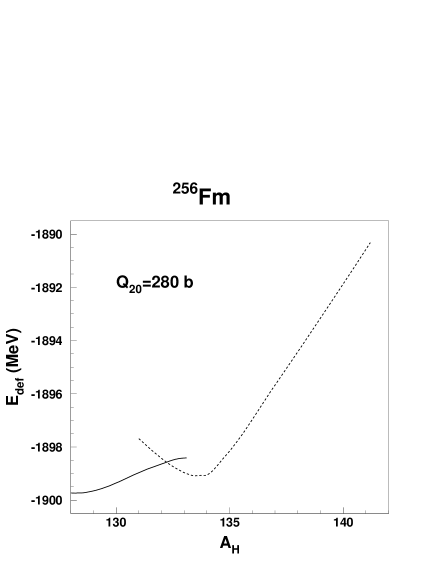
In this figure, the solid line represents solutions obtained by increasing the constraint on from 128 (symmetric solution) to about 133, beyond which these solutions become unstable. Similarly the dashed line corresponds to solutions obtained by decreasing the constraint on from about 141 to about 131, below which this kind of solutions does not exist. The two minima at and are therefore not connected through a continuous curve in Fig. 3, from which we learn that one or several additional degrees of freedom are missing in the description of this region of the energy surface (for example the fragment deformations). Nevertheless this does not cast any doubt on the existence of the two fusion valleys. Regarding the exact location of the asymmetric minimum on the dashed curve of Fig. 3, the present HFBCS calculations indicate that the mass of the heavy fragment varies very little in the asymmetric fusion valley, with an average integer value of 133.
Let us now turn to the 258Fm isotope. Its potential-energy surface presents some features in common with the one of 256Fm from the spherical point to the also present superdeformed minimum, with only symmetric solutions – corresponding to the solid line in Fig. 4 – in this elongation range.

As in 256Fm, octupole softness is observed around the top of the inner fission barrier. An asymmetric fission valley emerging in the vicinity of the superdeformed minimum is also present in 258Fm and plotted as a dashed line in Fig. 4. The nascent fragmentation around the exit point, namely approximately Xe+Pd, is similar to that obtained in 256Fm. However there are two major differences between 256Fm and 258Fm. The symmetrical solutions in 258Fm not only remain stable against left-right asymmetric deformations until scission, but they also give rise to two different families of nuclear shapes. The solutions with compact shapes constitute the symmetric compact fission (CF) path marked with full circles in Fig. 4 (labeled “sym. CF”) and those associated with elongated configurations form the symmetric elongated fission (EF) path marked with full triangles (labeled “sym. EF”).
A word of caution should be said here about the symmetric EF path. As mentioned in Sect. 2, the present calculations are done using a harmonic-oscillator basis size for the expansion of single-particle states. Even though this is large enough to show the existence of the symmetric EF path (that is, its stability with respect to left-right asymmetric deformations), it is not the case when addressing quantitative questions like the location of the exit point. This is why axial and left-right symmetric calculations are performed with a larger basis size . It then becomes possible to scan the potential-energy surface on a mesh , where and stand, respectively, for the center-of-mass distance and the fragment axial quadrupole moment (which is of course the same for each fragment because of the reflection symmetry). Since we deal here with very large elongations of the fissioning nucleus, the centers of mass of the pre-fragments (and a fortiori of the separated fragments) are well defined and it becomes more physical and intuitive to consider rather than . It is worth adding here that , and are not independent of each other since they obey the relation
| (24) |
where is the mass number of the fissioning nucleus.
In practice, it is extremely time consuming to optimize the basis parameters and at each grid point. Therefore I resort to an approximate procedure in which is optimized using a smaller basis corresponding to at an elongation b somewhat smaller than the elongation at which the symmetric EF valley appears. The resulting value of is then used over the whole range of deformations covered by the mesh ( and ). As we can see in Tab. 2, 0.42 is the approximate optimal value for .
| 1.6 | 1.8 | 2.0 | 2.2 | |||||||
|---|---|---|---|---|---|---|---|---|---|---|
| 0.38 | ||||||||||
| 0.40 | ||||||||||
| 0.42 | ||||||||||
| 0.44 | ||||||||||
| 0.46 |
As for , to which the results are not very sensitive (see Tab. 2), especially with the enlarged basis, an approximate variation with is taken into account (the actual values of appear in Fig. 7 discussed below). The resulting numerical uncertainties are not expected to drastically affect the relative position of the symmetric EF and CF valleys or the nuclear shape at the exit point of the EF valley.
The potential-energy surface obtained for 258Fm is displayed in three different forms: as a three-dimensional surface in Fig. 5, as a two-dimensional contour diagram in Fig. 6 and as a series of cuts at fixed -values in Fig. 7.


The deformation-energy curves as functions of in Fig. 7 exhibit two minima for fm. One at is associated with a configuration having very few nucleons in the neck (), corresponding thus to two separated, identical and nearly spherical fragments (symmetric CF valley). The other minimum varies with from 18 b to 45 b and the associated configuration has a finite neck radius (): it corresponds to the symmetric EF valley. The deformation-energy curves are all continuous except for fm (for which only the calculated points are plotted). Indeed two kinds of configurations coexist for . They are characterized by different -values: for the steep increasing branch (separated fragments) and for the other one (very elongated one-body-shaped configuration). From Fig. 7 we can approximately localize the exit point of the symmetric EF valley at about fm, with b.
From these results, we can deduce the variation of the deformation energy along the bottom of each valley as a function of the driving coordinate (see the upper panel of Fig. 8). It is also instructive to plot the same curves as functions of the quadrupole moment (see the lower panel of Fig. 8).

The variation of the energy is of course not affected by the choice of the driving coordinate since is a monotonically increasing function of as shown in Fig. 9, but the relative position of the two valleys can differ because of a projection effect. Indeed projecting the multidimensional energy surface onto a deformation subspace distorts it and the resulting pattern generally depends on the actual subspace. However, we can neglect this effect when comparing two valleys if the distortion is weak or the energy difference between the two valleys is large.

IV Discussion
IV.1 Asymmetric-to-symmetric transition in the fragment-mass distribution
From the features of the potential-energy surface we can obtain some information about the fragment-mass distribution in the spontaneous fission of 256Fm and 258Fm.
Starting from the ground state of 256Fm, the lowest and only continuous path leading to scission is asymmetric in its late stages, where the nascent fragments have a fairly constant mass ratio of beyond b. Under the assumption that the most probable fragmentation experimentally observed corresponds to the configuration just before neck rupture, that is, at the exit point of the fission valley, the mass distribution in the spontaneous fission of 256Fm is inferred to be asymmetric and peaked at and , only one mass unit away from the experimental value for the heavy fragment Flynn . This property has also been successfully described within the macroscopic-microscopic FRLDM model by Möller et al. Moller_Nature who found . Moreover, the calculations by Warda et al. Warda2002 have shown the same behavior in the transition from the ground-state symmetric path to the asymmetric fission valley. This can be seen in their Fig. 5 where their cuts in the direction at various elongations are similar to the HFBCS cuts along , since and turn out to be in a one-to-one correspondence along the cuts of Fig. 2 here. It is worth mentioning that the portion of the symmetric path between and b of their Fig. 3 does not correspond to local minima in the direction, as can be seen in their Fig. 5. Although the authors of Ref. Warda2002 found a clear left-right reflection asymmetry in their nuclear shapes along the EF path, they reported that the two nascent fragments have nearly equal masses, which they inferred in an unclear way from the integrated particle number as a function of plotted in their Fig. 4b. On the contrary, assuming that the neck most likely ruptures where its radius is minimum, the Figs. 4a and 4b of Ref. Warda2002 rather indicate that the heavy fragment has a mass of about 136 and an atomic number of about 52, in a much better agreement with the HFBCS results and the experimental data Flynn .
Contrary to 256Fm, the most favorable exit channel (i.e, the lowest continuous path) beyond the superdeformed minimum in 258Fm goes along the only symmetric path which eventually forks, instead of following the asymmetric EF valley because of the ridge separating them (at least 1.5 MeV high according to Warda et al. Warda2002 ). Whichever valley is eventually followed by the spontaneously fissioning nucleus towards scission, the outcome is the same in terms of mass fragmentation since in either valley the configurations are left-right symmetric. This leads thus to a symmetric mass distribution, as was obtained in all the other theoretical sudies and in agreement with experiment Hoffman_systematics ; Hulet_Fm258_PRL1986 .
IV.2 Bimodal fission in 258Fm
Let us now relate the properties of the valleys obtained in the potential-energy surface of 258Fm to the fragment total-kinetic-energy and mass distributions of this isotope.
The two symmetric valleys present a major difference associated with the nuclear shapes. Whereas the fissioning nucleus develops already in the early stages of the CF valley a narrow neck connecting two nearly spherical nascent fragments (see Fig. 10),
fm, b

fm, b

fm, b

fm, b

the neck of a fissioning nucleus following the symmetric EF valley persists over a much wider range of total elongation , with very elongated nascent fragments (see Fig. 11).
fm, b

fm, b

fm, b

fm, b

From a geometrical argument and approximating the total fragment kinetic energy by the Coulomb interaction energy (the dominant contribution) at scission, we can deduce that the fragments formed in the descent of the fissioning nucleus along the symmetric CF valley have a much higher kinetic energy than those associated with fission events from the symmetric EF valley. In both cases the fragment-mass distribution is expected to be symmetric since the parent nucleus fissions into two identical fragments in both valleys. More specifically, in the case where 258Fm undergoes fission through compact shapes like the ones displayed in Fig. 10, the high stiffness of the CF valley in the mass asymmetry direction, resulting from the strong shell effects in the nearly spherical and doubly magic nascent fragments, produces a mass distribution much narrower than the one corresponding to fission events through the symmetric EF valley.
These arguments show that the two HFBCS symmetric valleys are consistent with the kinetic-energy and mass-distribution properties of the two modes experimentally observed. Therefore it is natural to identify the symmetric EF path with the low-TKE mode, and the symmetric CF path with the high-TKE mode. Another argument in favor of the interpretation of the symmetric EF valley relies on the similarity between the nuclear shapes of Fig. 11 and those obtained in the liquid-drop model, with which the experimentally measured properties of the low-energy mode are consistent Hulet_Fm258_PRC1989 .
To provide more quantitative grounds to this interpretation, a discussion is now devoted to the estimation of the fragment total kinetic energy associated with each fission path. Let us assume that TKE is given by
| (25) |
where a small nuclear interaction energy and a somewhat larger prescission kinetic energy are added to the dominant Coulomb interaction energy . These three contributions have to be calculated just after neck rupture, that is, at scission. The Coulomb part does not pose any particular problem, so I focus on how to calculate the prescission kinetic and nuclear contributions. The relative energy of a scission configuration with respect to the initial energy of the fissioning nucleus (its ground-state energy in the present case of spontaneous fission) represents the available energy at scission. This energy can be shared among collective degrees of freedom other than deformation, essentially kinetic energy in the fission direction , and internal degrees of freedom as an “internal” excitation energy . We can thus write:
| (26) |
assuming that a physical scission configuration lies below the ground state to be accessible by tunneling from the ground-state well (). Since a static study is unable to provide the actual partitioning, I postulate an equipartition of between its two components
| (27) |
This approximation leads to values of prescission kinetic energy of about 10 MeV for the scission configurations considered in Tab. 3. This is of the same order as the one assumed by Brosa et al. Brosa_PhysRep1990 and consistent with the experimental average TKE-values, as well as the one found by Bonasera Bonasera in semi-classical dynamical calculations and by Abe et al. Abe from dynamical calculations based on the two-dimensional Langevin equation and the one-body dissipation mechanism. As for the nuclear interaction between the two fragments, it can be in principle calculated with the Skyrme force. This requires one to disentangle the three contributions of the nuclear energy of the whole system, namely the self-energies of the two fragments and the interaction energy between the fragments. This is ambiguous since one has to unfold the local densities into two sets of densities localized each in one of the fragments (with some overlap in the neck). However Pomorski and Dietrich Pomorski_Dietrich did the calculation in the case of two spherical nuclei and showed that the resulting potential is similar to the folded Yukawa-plus-exponential (YPE) potential proposed by Krappe, Nix and Sierk Krappe_Nix_Sierk . For this reason I use the latter potential, with the parameters of Ref. Sierk_rotating_nuclei .
The actual calculation of the different contributions of TKE for the three paths requires to determine a scission configuration for each path. As for the symmetric CF valley, I postulate that the shape at fm in Fig. 10 is the scission-point configuration. This is consistent with the criterion of Goutte et al. Goutte_U238 that, at scission, the nuclear density in the neck, at defined in Sect. 2, is 0.01 . In the CF valley this corresponds to fm. In fact it is remarkable that a scission point lies in the bottom of a valley. In contrast, no scission configurations are found along the symmetric or the asymmetric EF paths. It becomes more difficult and ambiguous to assign a scission point to each of these EF paths. However, in order to obtain an estimate of the associated kinetic energies, a kind of “sudden approximation” is used for an approximate calculation of . The two nascent fragments are approximated at the exit point by the equivalent coaxial spheroids having the same elongations and root-mean-square radii as the actual fragments. They result from a sudden neck rupture assumed to preserve the mass and charge asymmetries as well as the center-of-mass distance. The Coulomb interaction energy is calculated from the exact analytical expression of Quentin Quentin_Coulomb_interaction , whereas the nuclear interaction energy is calculated with the YPE potential by numerical integration.
The calculated results of , , and for each path are given in Tab. 3, together with the resulting kinetic-energy values rounded to the nearest integer.
| Valley | TKE | |||||||
|---|---|---|---|---|---|---|---|---|
| sym. CF | 15.0 | 289.26 | 1.27 | 238.6 | 1.7 | 7.1 | 244 | 129 |
| asym. EF | 18.2 | 462.14 | 1.55 | 204.7 | 1.4 | 11.7 | 215 | 141 |
| sym. EF | 22.0 | 714.36 | 1.86 | 178.5 | 5.2 | 10.4 | 184 | 129 |
The TKE-values for the symmetric CF and EF valleys lie in the ranges of the experimental high- and low-energy modes, respectively (see Fig. 7 of Ref. Hulet_Fm258_PRC1989 ). As for the asymmetric EF path, the HFBCS total kinetic energy is less than 220 MeV, which is consistent with the conclusion from Fig. 8 of Ref. Hulet_Fm258_PRC1989 that the fragments associated with the fission events above in the mass distribution have a TKE-value lower than 220 MeV. The authors of Ref. Hulet_Fm258_PRC1989 also reported that the mass-yield curve obtained by selecting spontaneous-fission events with MeV becomes asymmetric, from which it can be inferred that a significant number of symmetric pairs of fragments have a TKE-value between 200 and 220 MeV. However there is no evidence showing which type of symmetric configurations (elongated or compact) dominates in this kinetic energy range, or what the average TKE-value of fragment pairs with is. Therefore, based on kinetic-energy considerations, it seems possible that the asymmetric EF valley contributes to feed the low-energy mode, but probably less so than the symmetric EF one because of the ridge separating them.
Two recent studies support this suggestion. On the one hand, Zhao et al. Zhao_PRL1999 ; Zhao_PRC2000 deduced a deformation parameter of the scission configurations , which gives a measure of the deviation from two touching spheres, from experimental average total-kinetic-energy systematics. The value that these authors obtained from the average TKE-value of the low-energy mode in 258Fm is close to the average value corresponding to the asymmetric mode throughout the actinide region. It is interesting to note that the value I obtained for the asymmetric EF path is compatible with this systematics. On the other hand, Asano et al. Asano performed more recently dynamical calculations of the fragment kinetic-energy and mass distributions of 264Fm as well as the fragment-mass distributions of 256Fm and 258Fm, at an excitation energy of the compound nucleus of 10 MeV. These authors found that their distributions can be decomposed into three modes: a mass symmetric high-energy mode ( MeV), a mass asymmetric, low-energy mode (, MeV) and a symmetric, very low-energy mode ( MeV). Their calculated deformation parameters of the scission configurations associated with the first two modes are in very good agreement with the systematics of Zhao et al. Zhao_PRL1999 ; Zhao_PRC2000 . Despite the results obtained by Asano and collaborators correspond to a different isotope at a higher compound-nucleus excitation energy, they can be considered similar to those for 258Fm reported in Tab. 3.
Contrary to the above interpretation proposed for the calculated fission paths, Warda and collaborators Warda2002 ; Warda2003 identified the low-kinetic-energy mode with the asymmetric EF path only, since they do not seem to have found a symmetric EF path. In the same way as for 256Fm, they accounted for the symmetric character of the corresponding mass distribution by a mass symmetric division associated with left-right reflection asymmetric shapes. This explanation is not supported by the present HFBCS calculations. However, it would be very interesting to compare the exit points of the asymmetric EF valleys obtained in both models. Indeed the finite-range effect of the Gogny effective force may play a role in the nuclear interaction energy, therefore impacting the scission configurations and the total kinetic energies.
Finally the similar abundance experimentally observed for the two fission modes still needs to be explained. Since a static model cannot predict the branching ratio, I can only provide the following plausible qualitative argument. As we can see in Fig. 7, the symmetric EF path appears between fm and fm, at about the same energy as the CF path. This seems to indicate an equally important feeding of both valleys, leading to an expected branching ratio of about 1.
V Conclusion
The features of the potential-energy surface of the 256Fm and 258Fm
isotopes calculated within the HF(SkM*)+BCS(G) model successfully
account for the experimentally observed asymmetric-to-symmetric
transition in the mass distribution for spontaneous fission as
well as most of the measured properties of the bimodal spontaneous fission
in 258Fm. The HFBCS results suggest a different interpretation from
the one proposed by Warda et al. Warda2002 for the
low-energy mode in the spontaneous fission of 258Fm. This mode seems
to be better understood as a combination of a dominant one
corresponding to symmetric very elongated scission configurations,
and another one associated with asymmetric rather elongated
scission shapes (with a nearly spherical heavy fragment).
The estimates of the total kinetic energy for each component are compatible
with the experimental data Hulet_Fm258_PRC1989 as well as
with recent dynamical calculations Asano . As an alternate
dynamical approach, the virial-theorem-based approach, developped
and initially applied to heavy-ion collisions by I. N. Mikhailov
and collaborators virial_fusion , can also be applied to fission.
This work is underway for the symmetric fission of the 258Fm isotope
with microscopically calculated ingredients, namely the potential-energy surface obtained in the present study and the inertia parameters
calculated in the HFBCS framework as in Ref. mass_parameters .
ACKNOWLEDGEMENTS
I am deeply grateful to Arnie Sierk and Peter Möller for a careful reading of the manuscript and helpful comments, and I would like to thank Philippe Quentin and Patrick Talou for valuable discussions. This work has been supported by the U.S. Department of Energy under contract W-7405-ENG-36.
References
- (1) R. Brandt, S. G. Thompson, R. C. Gatti and L. Phillips, Phys. Rev. 131, 2617 (1963).
- (2) J. P. Balagna, G. P. Ford, D. C. Hoffman and J. D. Knight, Phys. Rev. Lett. 26, 145 (1971).
- (3) W. John, E. K. Hulet, R. W. Lougheed and J. J. Wesolowski, Phys. Rev. Lett. 27, 45 (1971).
- (4) K. F. Flynn, E. P. Horwitz, C. A. A. Bloomquist, R. F. Barnes, R. K. Sjoblom, P. R. Fields and L. E. Glendenin, Phys. Rev. C 5, 1725 (1972).
- (5) E. K. Hulet, R. W. Lougheed, J. H. Landrum, J. F. Wild, D. C. Hoffman, J. Weber and J. B. Wilhelmy, Phys. Rev. C 21, 966 (1980).
- (6) D. C. Hoffman, J. B. Wilhelmy, J. Weber, W. R. Daniels, E. K. Hulet, R. W. Lougheed, J. H. Landrum, J. F. Wild and R. J. Dupzyk, Phys. Rev. C 21, 972 (1980).
- (7) E. K. Hulet, J. F. Wild, R. J. Dougan, R. W. Lougheed, J. H. Landrum, A. D. Dougan, M. Schädel, R. L. Hahn, P. A. Baisden, C. M. Henderson, R. J. Dupzyk, K. Sümmerer and G. R. Bethune, Phys. Rev. Lett. 56, 313 (1986).
- (8) V. E. Viola, K. Kwiatkowski and M. Walker, Phys. Rev. C 31, 1550 (1985).
- (9) E. K. Hulet, J. F. Wild, R. J. Dougan, R. W. Lougheed, J. H. Landrum, A. D. Dougan, P. A. Baisden, C. M. Henderson, R. J. Dupzyk, R. L. Hahn, M. Schädel, K. Sümmerer and G. R. Bethune, Phys. Rev. C 40, 770 (1989).
- (10) H. J. Lustig, J. A. Maruhn and W. Greiner, J. Phys. G: Nucl. Phys. 6, L25 (1980).
- (11) U. Brosa, S. Grossman and A. Müller, Z. Phys. A 325, 241 (1986).
- (12) P. Möller, J. R. Nix and W. J. Swiatecki, Nucl. Phys. A469, 1 (1987); Nucl. Phys. A492, 349 (1989).
- (13) P. Möller, D. G. Madland, A. J. Sierk and A. Iwamoto, Nature (London) 409, 785 (2001).
- (14) V. V. Pashkevich, Nucl. Phys. A477, 1 (1988).
- (15) S. Ćwiok, P. Rozmej, A. Sobiczewski and Z. Patyk, Nucl. Phys. A491, 281 (1989).
- (16) M. Warda, J. L. Egido, L. M. Robledo and K. Pomorski, Phys. Rev. C 66, 014310 (2002).
- (17) M. Warda, J. L. Egido, L. M. Robledo and K. Pomorski, Phys. At. Nucl. 66, 1178 (2003).
- (18) M. Warda, K. Pomorski, J. L. Egido and L. M. Robledo, Int. J. Mod. Phys. E 13, 169 (2004).
- (19) A. Staszczak, J. Dobaczewski and W. Nazarewicz, Int. J. Mod. Phys. E 14, 395 (2005).
- (20) T. Asano, T. Wada, M. Ohta, T. Ichikawa, S. Yamaji and H. Nakahara, J. Nucl. Radiochem. Sci. 5, 1 (2004).
- (21) R. C. Ragaini, E. K. Hulet, R. W. Lougheed and J. Wild, Phys. Rev. C 9, 399 (1974).
- (22) L. Bonneau and P. Quentin, in Proceedings of the Third International Workshop on Nuclear Fission and Fission-Product Spectroscopy, Cadarache, France, 2005, edited by H. Goutte, H. Faust, G. Fionni and D. Goutte (AIP, Melville, New York, 2005), p. 77.
- (23) L. Bonneau, P. Quentin and D. Samsœn, Eur. Phys. J. A 21, 391 (2004).
- (24) H. Goutte, J.-F. Berger, P. Casoli and D. Gogny, Phys. Rev. C 71, 024316 (2005).
- (25) L. Bonneau and P. Quentin, in Proceedings of the Third International Workshop on Nuclear Fission and Fission-Product Spectroscopy, Cadarache, France, 2005, edited by H. Goutte, H. Faust, G. Fionni and D. Goutte (AIP, Melville, New York, 2005), p. 297.
- (26) M. Bender, K. Rutz, P.-G. Reinhard and J. A. Maruhn, Eur. Phys. J. A 7, 467 (2000).
- (27) D. Vautherin, Phys. Rev. C 7, 296 (1973).
- (28) J. C. Slater, Phys. Rev. 81, 385 (1951).
- (29) J. W. Negele and D. Vautherin, Phys. Rev. C 5, 1472 (1972).
- (30) P. Gombas, Ann. Phys. (Leipzig) 10, 253 (1952).
- (31) H. Flocard, P. Quentin, A. K. Kerman and D. Vautherin, Nucl. Phys. A203, 433 (1973).
- (32) L. Bonneau and P. Quentin, Phys. Rev. C 72, 014311 (2005).
- (33) J.-F. Berger, J. D. Anderson, P. Bonche and M. S. Weiss, Phys. Rev. C 41, R2483 (1990).
- (34) J.-F. Berger, M. Girod and D. Gogny, Nucl. Phys. A428, 23c (1989).
- (35) U. Brosa, S. Grossman and A. Müller, Phys. Rep. 197, 167 (1990).
- (36) A. Bonasera, Phys. Rev. C 34, 740 (1986).
- (37) Y. Abe, S. Ayik, P.-G. Reinhard and E. Suraud, Phys. Rep. 275, 49 (1996).
- (38) K. Pomorski and K. Dietrich, Z. Phys. A 295, 355 (1980).
- (39) H. J. Krappe, J. R. Nix and A. J. Sierk, Phys. Rev. C 20, 992 (1979).
- (40) A. J. Sierk, Phys. Rev. C 33, 2039 (1986).
- (41) P. Quentin, J. Phys. (Paris) 30, 497 (1969).
- (42) Y. L. Zhao, I. Nishinaka, Y. Nagame, M. Tanikawa, K. Tsukada, S. Ichikawa, K. Sueki, Y. Oura, H. Ikezoe, S. Mitsuoka, H. Kudo, T. Ohtsuki and H. Nakahara, Phys. Rev. Lett. 82, 3408 (1999).
- (43) Y. L. Zhao, Y. Nagame, I. Nishinaka, K. Sueki and H. Nakahara, Phys. Rev. C 62, 014612 (2000).
- (44) I. N. Mikhailov, T. I. Mikhailova, M. Di-Toro, V. Baran and Ch. Briançon, Nucl. Phys. A604, 358 (1996).
- (45) E. Kh. Yuldashbaeva, J. Libert, P. Quentin and M. Girod, Phys. Lett. B461, 1 (1999).