Also at]Instituut voor Kern- en Stralingsfysica, University of Leuven, Celestijnlaan 200 D, B-3001 Leuven, Belgium
Alpha Decay Hindrance Factors: A Probe of Mean Field Wave Functions
Abstract
A simple model to calculate -decay Hindrance Factors is presented. Using deformation values obtained from PES calculations as the only input, Hindrance Factors for the -decay of Rn- and Po-isotopes are calculated. It is found that the intrinsic structure around the Fermi surface determined by the deformed mean field plays an important role in determining the hindrance of -decay. The fair agreement between experimental and theoretical Hindrance Factors suggest that the wave function obtained from the energy minima of the PES calculations contains an important part of the correlations that play a role for the -decay. The calculated HF that emerges from these calculations render a different interpretation than the commonly assumed n-particle n-hole picture.
pacs:
23.60.+e decay 27.80.+wI INTRODUCTION:
The recent experimental exploration of the neutron deficient Pb-region has given new insight into the low lying excitations of atomic nucleiwau941 . In particular, the discovery of the triplet spin states as the lowest excitations in 186Pb reveals the coupling of single particle motion to the collective shape degree of freedom in a striking mannerand00 . The quantitative description of these excitations as well as their isotopic and isobaric dependence is a real challenge to nuclear structure models. The balance of prolate and oblate shapes e.g. depends crucially on the iso-spin dependence of the spin orbit interaction as well as the particular shape of the nuclear potentialtaj01 .
This paper will focus on the decay as a tool to understand the microscopic structure related to the different shapes in the Pb-region within the frame work of the mean field model. To calculate the absolute values of the decay rate is a problem which is still not fully solved. Instead, we will investigate the ratio of the Hindrance Factors of the decay to different states. In this manner, only parts of the absolute decay width needs to be taken into account making the problem more tractable. We limit the discussion to decay of the ground state of even-even nuclei to the states in the daughter nuclei; transitions.
The Hindrance Factor is the ratio between the reduced decay widths, labeled , of the ground state-to-ground state decay and the reduced decay width of the decay to an excited state in the daughter nucleus ras59 . The experimental reduced decay widths are calculated using a spherical potential barrier. In principle, using a deformed potential barrier could influence the calculated -value, but the effect is expected to be very small for the zero angular momentum decays treated in this work. The Hindrance Factor is independent of the -decay energy and can therefore be used to compare the intrinsic mechanisms that induce the -decay process. This is an important property in the study of shape coexisting nuclei, since the decay between states with similar single particle structure is thought to take place more easily than that between states with different single particle structure. In the present work the single particle structure is determined by the deformation parameters of the universal parameter Woods-Saxon potential, see ref. naz85 . A study of the Hindrance Factors can therefore help in establishing the deformation of the ground state and the excited states of the daughter nucleus if the deformation of the decaying nucleus is known or vice versa.
Earlier work on Hindrance Factors have used a two-level mixing model based on the spherical shell model kh87 . In this model the intrinsic decay rates have been related to each other through experimentally measured Hindrance Factors dup90 ; dup00 . A microscopic model based on RPA calculations has been presented in ref. del96 . In the present work we start from the mean field wave function as obtained from Potential Energy Surface (PES) calculations. In this way, the deformation of each state is derived microscopically and is not a free parameter of the calculations.
Section 1 of this paper gives an introduction to the subject of Hindrance Factors. Section 2 describes the model used in our calculations. In section 3 we show the dependency of Hindrance Factors on properties such as deformation, pairing correlations and particle number. Section 4 is a comparison between the spherical shell model picture and the mean-field approach applied in our model. In section 5 we present and discuss results from calculations using the model described in section 2.
II MODEL:
The -particle decay width can be factorized into two parts lov98 ,
| (1) |
where is the Coulomb penetrability at the distance between the center of mass and the -particle, and is the reduced decay width ras59 . Here is the cluster formation amplitude.
The Hindrance Factor is given by the ratio of the absolute value squared of the -particle formation amplitudes for the decays from the ground state of the mother nucleus to the ground state (gs) and the excited state (es) of the daughter nucleus. This can be written as
| (2) |
where the ground state to ground state decay is taken to be non hindered, i. e. the Hindrance Factor is equal to one. Further, the formation amplitude for a decay from state B in the mother nucleus to the state A in the daughter nucleus can be written as lov98
| (3) |
If we rewrite the equation 3 in Fock space we obtain
| (4) |
By using Thouless theorem, see rs80 , it is possible to connect two HFB vacuum states with different deformations. Therefore the mother nucleus can be expanded in terms of two pair excitations of the daughter nucleus, although the deformation of the two states may differ. For a more thorough investigation of the problem, see ref. del98 . An expression for the mother nucleus as a four particle excitation of the daughter nucleus is obtained,
| (5) |
where is a pair of protons and is a pair of neutrons. The factors and are related to the pairing densities
| (6) |
and can readily be evaluated using the Onishi formula rs80 , yielding the expression
| (7) |
where
| (8) |
and the and are the matrices of the Bogoliubov transform for the daughter and mother nuclei. This gives a total expression for the formation amplitudes as
| (9) |
The integral can be solved analytically by expressing the wave function of the -particle in terms of Harmonic Oscillator wave functions and using the Moshinsky brackets mos59 to transform to a center of mass system. However it turns out pog69 that for the special case of an -particle with angular momentum 0 all terms of the integral
| (10) |
are positive and can as a first approximation be replaced by an average value . If we now evaluate the expression 3 for the decays between two states we get
| (11) |
where the is the ground state and is the excited state. The physical meaning of equation II is that the pair transfer amplitude for protons times that for neutrons is the essential quantity that determines the ease with which the mother nucleus decays into a corresponding state of the daughter nucleus.
III DEPENDENCY OF THE HINDRANCE-FACTOR ON PAIRING AND DEFORMATION:
The deformation affects the Hindrance Factor in two ways. First, the degeneracy of levels at spherical shape is lifted. This means that two nuclei with different shapes have the levels rearranged and different levels become occupied at the Fermi surface. Without pairing interaction this would mean that the overlap between two wave functions describing a nucleus at different shapes becomes zero as soon as we encounter a level crossing.
Secondly, the spherical components building up each single particle level change smoothly with deformation. Therefore the hindrance factors are not constant even in absence of level crossings.
The pairing interaction results in a smoothing of the differences in level structure for nuclei with different shapes. This effect only occurs in the vicinity of the Fermi surface, in an energy window that is determined by the pairing strength. As a large part of this work focuses on the Pb-region we have the further complication of the large proton energy gap between proton numbers 82 and 84. The energy gap does not allow for a non trivial solution to the BCS-equation. Since the vanishing of the BCS solution is non physical and in order to mimic the correlations that are indeed present in the ground state wave function we have increased the pairing strength by 15% which guarantees a non trivial solution. The odd even mass difference we obtain are well within the experimental ones, see also the discussion in ref xu99 . This procedure is necessary in order to compare decays to different states in a meaningful manner.
Figure 1 shows that the HF is only weakly dependent on deformation in an interval from to . By comparing to Fig. 3, one notices that this is the range in deformation, where there are no level crossings for proton number Z=82. However, beyond these values in deformation, we encounter one level crossing at oblate shape and several at prolate shape. This is reflected in Fig. 1, where the increase in HF is considerably stronger at the prolate side compared to the oblate side. Note the increase around spherical shape due to reduced pairing correlations as a consequence of the Z=82 shell gap.
In fig. 2 the dependence on the deformation parameter is shown. Similarly to fig. 1, in a rather broad range of deformation, from to the increase in the HF is rather modest. However, for larger difference in between mother and daughter nucleus, the HF increases steeply. In fact, the increase in HF is exponential, as shown in the inset. In the calculations of Fig. 2 we choose the mother nucleus to be prolate. When starting from an oblate deformation for the mother nucleus, we obtain a similar curve, but reflected at . Our calculations imply, that the decay from oblate to prolate is essentially forbidden. However, we also investigated the case when the mother has maximum triaxial deformation, i.e. a value of -30. Then the hindrance increases only with a factor of when the daughter is prolate or oblate, respectively. Since true wave function has a certain spread in and , the decay from prolate to oblate will proceed via the tail of the wave function. This is of course beyond the mean field prescription. A soft potential in , resulting in a large spread of the wave function will result in a pronounced decrease of the HF.
IV COMPARISON BETWEEN THE PARTICLE-HOLE PICTURE AND THE MEAN-FIELD PICTURE
Shape coexistence has been described in the shell model in terms of specific particle-hole excitations with respect to the spherical core, see woo92 . In the Pb-region, the 2p-2h, 4p-4h or 6p-6h proton excitation across the magical shell gap induce deformation that can result in oblate or prolate shapes. The spherical ground states in the Polonium isotopes are characterized by the corresponding 2p-0h states and the 0p-2h states correspond to the spherical Hg-isotopes. The 2p-2h excitations are very costly in energy. On the other hand, the energy gain due to pairing interaction and iso-scalar quadrupole-quadrupole can partly balance the energy loss and result in low lying deformed states. Hence, in a qualitative fashion, one has been able to account for the parabolic dependence as a function of neutron number of the deformed states in the neutron deficient Pb region as well as other regions of the nuclear chart, see e.g. the discussion in Ref. kh89 .
The shell model description can be linked to the deformed Nilsson (or Hartree-Fock) scheme, by associating the particle hole excitations to the specific level crossings, present in the Nilsson diagram, which pin down the underlying structure of deformed states, see kh89 . This connection is very valuable, since it enables the comparison of the underlying structure for the two basic nuclear structure models. However, two aspects need to be clarified in this respect: i) within the shell model, there is no real distinction between oblate and prolate shapes. In the Sn-region e.g., 2p-2h excitations corresponds to prolate shapes in the mean field model, whereas the same excitation in the Pb region results in oblate shapes. ii) care has to be given to the labeling of the np-nh excitations. The 2p-2h configuration in the Pb-region e.g., does not agree at all with the microscopic structure of the corresponding oblate states in the mean-field. In fact, the ’’ hole state at oblate deformation is dominated by the according to the Woods-Saxon model, and has only a smaller contribution from the , see ref. and03 . The configuration mixing that is induced by deformation is very pronounced for this particular case. This is of course essential for a microscopic understanding of the deformed states, since the quadrupole moment of the hole is very different from that of the . Realistic shell model calculations in the Pb region with a broken proton and neutron core are far from being feasible, but structure information from the deformed mean field can be used as an important input to shell model calculations.

Allowed and forbidden decays in the np-nh model can be illustrated with figure 2. of ref. dup00 . The neutrons are considered as spectators not influencing the hindrance of the decay. Therefore the hindrance of the -decay is discussed in terms of two particle (proton) removal. An allowed decay is characterized by the removal of two particles from the mother nucleus forming an existing state in the daughter nucleus. The mother nucleus is in its ground state considered to be a 2-particle state of the daughter nucleus. There are two allowed decays from a spherical ground state; removal of the two valence particles gives a decay to the spherical state in the daughter nucleus; removal of two particles from the core forms a 2p-2h state in the daughter nucleus corresponding to an oblate shape. The decay to a prolate 4p-4h state is forbidden since it is a two step process. First two particles have to be removed from the core, and after that another 2p-2h excitation has to take place giving a final 4p-4h state. This means that the only allowed decay from a prolate state in the mother nucleus is to a prolate state in the daughter nucleus. One may also state that the -decay can only remove particles, not holes, i.e. a 4p-4h configuration will remain at least a 4h configuration in an allowed decay. The different decays are attributed with a hindrance taken from the assumed pure (unmixed) decay between and dup00 . Once these pure states are mixed, a formula for the Hindrance Factors can easily be obtained. The decay properties of these mixed states can be used to determine the mixing parameters.
In the mean-field picture the different states are viewed as 0-quasi particle states with different deformations, described by the standard deformation parameters and , see ref. rs80 . From figure 1, one can conclude that the underlying single particle structure is changing with deformation, due to the presence of distinct level crossings at oblate and prolate shapes. This is reflected by the slope of the hindrance factor as a function of . However, level crossings are not restricted to spherical shapes but a generic feature of a many-body fermionic system. In order to obtain a deeper understanding of the HF with respect to the shell model like description, we also investigated the neutron and proton contributions to the HF.
According to Eqs. 6,10, the HF are obtained as the product of proton and neutron contributions, respectively. Therefore, one can easily decompose the HF accordingly, see Figs. 4 and 5. Interestingly, the neutron contribution to the hindrance factor is of similar strength as the proton part. Minor differences are seen at spherical shape and at the largest deformations. Since the neutrons in general are treated as spectators, see e.g. Ref. dup00 our results suggest that this is not the case. Therefore, in spite of the appealing clarity of the intruder picture in terms of the np-nh excitations with respect to the magic shell gap at Z=82, there is little evidence that the Hindrance Factor is dominated by the change of the proton configuration. In other words, even if the proton Fermi level would be placed in the middle of the shell, as it is the case for the neutrons, the calculated HF would be similar. One may conclude, that the similarity of proton and neutron contribution to the HF indeed indicates that this is a generic feature of the nuclear spectrum, and not so sensitive to the details of the shell structure.
V RESULTS AND CONCLUSIONS
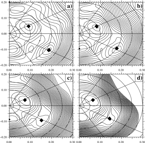
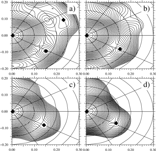
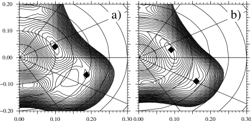
The deformation values used for the calculations of the hindrance factors in equation II are determined from the minima of the PESs, see figures 6, 7, 8. Extensive PES calculations of the isotopes have been presented earlier in ref. oro99 . We start with the decays of selected and nuclei, which are calculated to have well separated minima. The results of the calculations are presented in table 1. Given the simplicity of the model, the calculations agree surprisingly well with the data. The results for the decays of the heavier to are better reproduced than that of the to decays, possibly indicating that the deformation of the oblate states in the isotopes is slightly underestimated in the PES calculations. Still, the trend is nicely reproduced. For the lightest isotope, , the prolate state is calculated to have the lowest energy, which is why the hindrance of the decay to the excited (prolate) state in is less than one. Also for this case, we reproduce the trend of this change, but in absolute numbers the calculated Hindrance Factor is three orders of magnitude off.
| Mother Nucleus | ||
|---|---|---|
| 2.82 | 3.2(5)111Fromvel03 | |
| 2.38 | 2.6(2)111Fromvel03 | |
| 2.41 | 1.2(2)111Fromvel03 | |
| 1.9E-5 | 0.08(3)111Fromvel03 | |
| 5.46 | 19(6)222Fromwau941 | |
| 10.4 | 85(7)333From bij95 |
A remark is necessary concerning the important role played by the small quadrupole deformation, , of the isotopes, see fig. 6. This slight deformation, in combination with the reduced pairing correlations at spherical shape, is essential to reproduce the similar strengths of the decay to the spherical and oblate states, respectively, in the -isotopes. If the isotopes would be spherical in the mean field calculations the decay from spherical to oblate would be strongly suppressed. This is demonstrated in Fig. 9 showing that for spherical shapes, the decay to either oblate or prolate is essentially forbidden. This is also at variance with the simple np-nh shell model picture where the decay from spherical to oblate is allowed.
| Mother Nucleus | State in Daughter | 11footnotemark: 1 | |
| 1.0 | 1.0 | ||
| 1.9 | 0.56(7) | ||
| 2.8 | 50 | ||
| 57 | 1.0 | ||
| 0.20 | 0.56(7) | ||
| 8.4 | 50 | ||
| 1.0 | 1.0 | ||
| 1.3 | 0.57(12) | ||
| 3.5 | 2.4(9) | ||
| 44 | 1.0 | ||
| 0.17 | 0.57(12) | ||
| 63 | 2.4(9) | ||
| 300 | 1.0 | ||
| 3.4 | 0.57(12) | ||
| 0.20 | 2.4(9) |
The steep increase in hindrance for the decay of has earlier been attributed to a phase transition, see del96 , where the structure has changed from the decay of the heavier isotope . In our calculations the increase of hindrance is an effect of the increased deformation of the excited state in compared to that of the heavier isotope . Since we are in a region of a level crossing, see figures 1 and 3, the calculations are very sensitive to small deformation changes as they give a large change in single particle structure. This is also in good agreement with the PES calculations presented in figures 6 and 8, where only a slight difference in deformation between the two Radon isotopes doubles the hindrance of the decay. One notices from figures 2 and 1 that only slight changes in the equilibrium deformation are necessary in order to reproduce experimental data.
We also calculated the Hindrance Factors for the the decays and . For these decays the different minima in the PES of both mother and daughter nuclei are less well separated. In general, one expects the mean field to give a proper description only when the energy minima are sufficiently deep, and the spreading of the wave function can be neglected. Certainly this is not the case in the light and isotopes. However, for pedagogical reasons and also to indicate the limitations of the present approach, we compare the calculated and experimental values in table 2.
An interesting feature in table 2. is the coupling between states of different deformations which is not in agreement with the particle hole picture, see ref. dup00 . Note also the influence of triaxiality visible from the drastic change in hindrance for the decays oblate to prolate in the two different Po isotopes. The triaxiality parameter is for and for . The separation of the minima in deformation and energy obtained from the PES calculations is now the limiting factor of calculations. Creating a proper collective wave function by means of the Generator Coordinate Method (GCM) e.g. is a future project that may enable us to take into account the mixing of the wave functions at different deformation, resulting in meaningful calculations of all -decaying shape coexisting nuclei. GCM calculations has been performed for the mass region, see ref. dug03 , but has been restricted to axially deformed states.
To conclude, a simple model to calculate the Hindrance Factors for alpha decay is presented. Both the energy minima and the hindrance factor calculations are performed using the same Woods-Saxon potential with universal parameters. Deformation values are taken from microscopic calculations and not free parameters. In this respect, one may view the alpha decay as an important probe to the mean field wave function. Our calculations show that the HF factors depend only modestly on deformation changes, as long as these are not large. However, as soon as the underlying s.p. structure is changed due to a level crossing e.g., there appears an exponential increase in the HF with deformation. Our calculations reproduce the experimental trends for the cases where one deals with clearly separated minima in the PESs. This indicates that the mean field wave function contain an essential part of the correlations that are responsible for the formation of an alpha particle. In this context it is important to point out the role of the calculated small deformation values in the Po- and Rn-region which are normally treated as spherical. Our calculations also reveal that both protons and neutrons contribute to the HF in a similar fashion, which is in variance with the simple shell model like description.
References
- (1) J. Wauters, N. Bijnens, P. Dendooven, M. Huyse, H.-Y. Hwang, G. Reusen, J. von Schwarzenberg, P. Van Duppen, The ISOLDE Collaboration, R. Kirchner, and E. Roeckl. Phys. Rev. Lett., 72:1329, 1994.
- (2) A. N. Andreyev, M. Huyse, P. Van Duppen, L. Weissman, D. Ackermann, J. Gerl, F. P. Hessberger, S. Hofmann, A. Kleinböhl, G. Münzenberg, S. Reshitko, C. Schlegel, H. Schaffner, P. Cagarda, M. Matos, S. Saro, A. Keenan, C. Moore, C. D. O’Leary, R. D. Page, M. Taylor, H. Kettunen, M. Leino, A. Lavrentiev, R. Wyss, and K. Heyde. Nature, 405:430, 2000.
- (3) N. Tajima and N. Suzuki. Phys. Rev. C., 64:1, 2001.
- (4) J. O. Rasmussen. Phys. Rev., 113:1593, 1959.
- (5) W. Nazarewicz, J. Dudek, R. Bengtsson, T. Bengtsson, and I. Ragnarsson. Nucl. Phys. A, 435:397, 1985.
- (6) K. Heyde, J. Jolie, J. Moreau, J. Ryckebusch, and M. Waroquier. Nucl. Phys. A, 466:189, 1987.
- (7) P. Van Duppen, M. Huyse, and J. L. Wood. J. Phys. G, 16:441, 1990.
- (8) P. Van Duppen and M. Huyse. Hyp. Int., 129:149, 2000.
- (9) D. S. Delion, A. Florescu, M. Huyse, J. Wauters, P. Van Duppen, ISOLDE Collaboration, A. Insolia, and R. J. Liotta. Phys. Rev. C, 54:1169, 1996.
- (10) R. G. Lovas, R. J. Liotta, A. Insolia, K. Varga, and D. S. Delion. Phys. Rep., 294:265, 1998.
- (11) P. Ring and P. Schuck. The Nuclear Many-Body Problem. Springer-Verlag, Berlin, 1980.
- (12) D.S. Delion, , and R.J. Liotta. Phys. Rev. C, 58:2073, 1992.
- (13) M. Moshinsky. Nucl. Phys., 13:104, 1959.
- (14) J. K. Poggenburg, H. J. Lang, and J. O. Rasmussen. Phys. Rev., 181:1697, 1969.
- (15) F. R.Xu, R. Wyss, and P. M. Walker. Phys. Rev. C, 60:1, 1999.
- (16) J. L. Wood, K. Heyde, W. Nazarewicz, M. Huyse, and P. van Duppen. Phys. Rep., 215:101, 1992.
- (17) K. Heyde, C. De Coster, J. Ryckebusch, and M. Waroquier. Phys. Let. B, 218:287, 1989.
- (18) A. N. Andreyev, D. Ackermann, F.P. Heßberger, K. Heyde, S. Hofmann, M. Huyse, D. Karlgren, I. Kojouharov, B. Kindler, B. Lommel, G. Münzenberg, R. D. Page, K. Van de Vel, W. B. Walters, and R. Wyss. To be published.
- (19) A. M. Oros, K. Heyde, C. De Coster, B. Decroix, R. Wyss, B. R. Barett, and P. Navratil. Nucl. Phys. A, 645:107, 1999.
- (20) K. Van de Vel, A. N. Andreyev, D. Ackermann, H. J. Boardman, P. Cagardia, J. Gerl, F. P. Heßberger, S. Hofmann, M. Huyse, D. Karlgren, I. Kojouharov, M. Leino, B. Lommel, G. Münzenberg, C. Moore, R. D. Page, S. Saro, P. Van Duppen, and R. Wyss. Phys. Rev. C, 68, 2003.
- (21) N. Bijnens, P. Decrock, S. Franchoo, M. Gaelens, M. Huyse, H.-Y. Hwang, I. Reusen, J. Szerypo, J. von Schwarzenberg, J. Wauters, J.G. Correira, A. Jokinen, P. Van Duppen, and The ISOLDE Collaboration. Phys. Rev. Lett., 75:4571, 1995.
- (22) T. Duguet, M. Bender, P. Bonche, and P. H. Heenen. Phys. Lett. B, 559:201, 2003.