Left-handed nuclei
Abstract
The orientation of the angular momentum vector with respect to the triaxial density distribution selects a left-handed or right-handed system principal axes. This breaking of chiral symmetry manifests itself as pairs of nearly identical -bands. The chiral structures combine high-j particles and high-j holes with a triaxial rotor. Tilted axis cranking calculations predict the existence of such configurations in different mass regions. There is experimental evidence in odd-odd nuclei around mass 134. The quantized motion of the angular momentum vector between the left- and right-handed configurations, which causes the splitting between the chiral sister bands, can be classified as tunneling (chiral rotors) or oscillation (chiral vibrators).
1 Introduction
Chirality is a common property of molecules. Fig. 1 shows a simple example. The 2-iodubutene contains a stereo center - the C atom -, to which the four different groups are attached. If one selects the bond to the group CH3CH2, the three groups I, H, CH3 form a right-handed or a left-handed screw. These two ”enatiomers” are related to each other by mirror reflection. Complex bio-molecules are all chiral. Chirality is very obvious for the DNA double-helix. Although in principle two entantiomers exist, which have exactly the same binding energy, organisms synthesize only one. The reason is that the DNA blueprint provides only for one. Since the function of bio-molecules depends critical on their geometry, (e.g. the key-lock mechanism of enzymes) the other enantiomer with the mirror-geometry may not function in the organism. Life based on the opposite enantiomers of all bio-molecules should be possible. How came the choice about in the beginning of evolution? Most likely, it was just by accident. However, there are speculations that the chirality of elementary particles might have played a role.
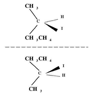
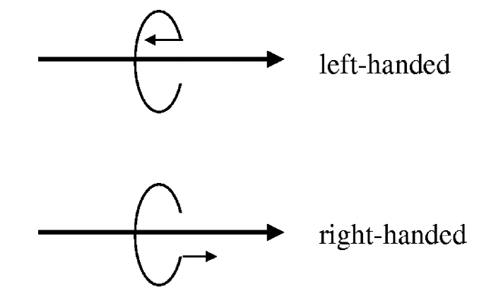
Fig. 2 illustrates chirality of a mass-less particle. The spin can be parallel or anti-parallel to particle momentum. Since the spin of the particle is an axial vector, it defines the a sense of rotation and the two orientations correspond to a right-handed and a left-handed system. The neutrinos, which appear only as left-handed species, introduce chiral asymmetry into the world. The chirality of molecules is of geometrical nature, the chirality of mass-less particles is dynamical.
Nuclei have been thought as being achiral, because they consist of only two species of nucleons and have relatively simple shapes as compared to molecules, However, Meng and Frauendorf chiral recently pointed out that angular momentum adds a new dimension, such that the rotation of triaxial nuclei may attain a chiral character. The lower panel of Fig. 3 illustrates this surprising possibility. We denote the three principal axes (PA) of triaxial density distribution by l, i, and s, which stand for long, intermediate and short, respectively. The angular momentum vector introduces chirality by selecting one of the octants. In four of the octants the axes l, i, and s form a left-handed and in the other four a right-handed system. This gives rise to two degenerate rotational bands because all octants are energetically equivalent. Hence the chirality of nuclear rotation results from a combination of dynamics (the angular momentum) and geometry (the triaxial shape).
2 Tilted Axis Cranking Calculations.
If we speak about the shape of a nucleus, we mean the shape of its density distribution. The symmetry of the density distribution -spherical or deformed- decides if the spectrum will be irregular or show rotational bands. The density distribution is found by means of mean field approaches, like the various types of the Hartree-Fock calculations or the Strutinsky method. For large angular momentum one has to use the Cranking generalizations of these methods, which describe an uniformly rotating mean field. In these studies, one used to assume that the axis of uniform rotation coincides with one of the principal axes of the density distribution, as it its the case for molecules. Frauendorf tac demonstrated that nuclei are different from molecules. They may uniformly rotate about an axis that is tilted with respect to the principal axes of the density distribution. The Tilted Axis Cranking model (TAC) Kerman ; Frisk ; tac allow us to calculate the orientation of the rotational axis. TAC consist in applying one of mean field approximations to the two-body Routhian
| (1) |
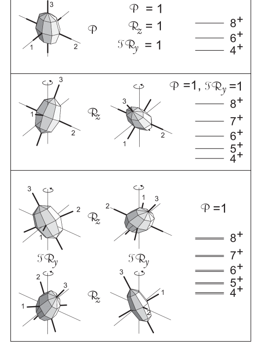
Here, is the two-body Hamiltonian of choice and the angular momentum component along the z-axis which is the rotational axis. The new element as compared to traditional cranking calculations is to allow for all orientations of the density distribution with respect to the z-axis. Fig. 3 illustrates how changing the orientation of the rotational axis leads to different discrete symmetries, which show up in the level sequence of rotational bands. In the upper panel the axis of rotation (which is chosen to be z) coincides with one of the PA, i. e. the finite rotation . This symmetry implies the signature quantum number , which restricts the total angular momentum to the values , with integer ( band) bf . In the middle panel the rotational axis lies in one of the planes spanned by two PA (planar tilt). Since now , there is no longer a restriction of the values can take. The band is a sequence of states the of which differ by 1 ( band). There is a second symmetry in the upper two panels: The rotation transforms the density into an identical position but changes the sign of the angular momentum vector . Since the latter is odd under the time reversal operation , the combination .
In the lower panel the axis of rotation is out of the three planes spanned by the PA. The operation . It changes the chirality of the axes l, i and s with respect to the axis of rotation . Since the left- and the right-handed solutions have a the same energy, they give rise to two degenerate bands. They are the linear combinations of the left- and right-handed configurations , which restore the spontaneously broken symmetry.
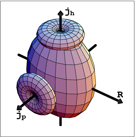
Fig. 4 illustrates how such a solution may arise. The proton aligns its angular momentum with the short axis of the density distribution. This orientation maximizes the overlap of its orbital with the triaxial density, which corresponds to minimal energy, because the core-particle interaction is attractive. The neutron hole aligns its angular momentum with the long axis. This orientation minimizes the overlap of its orbital with the triaxial density, which corresponds to minimal energy, because the core-hole interaction is repulsive. The angular momentum of the core is of collective nature. It likes to orient along the intermediate axis, which has the largest moment of inertia, because the density distribution deviates strongest from rotational symmetry with respect to this axis.
The chiral configuration is rather special. The shape must be triaxial, and there must be high-j particles and high-j holes. The existence of such a structures and their location in the nuclear chart must by studied by means of microscopic TAC calculations. The status of these explorations will be discussed in the last section. Dimitrov, Frauendorf and Dönau chiralprl found the first completely self-consistent chiral solution for Pr75 with the maximal triaxiality of . Fig. 5 shows that in this nucleus two bands, which are based on the configuration, merge forming a doublet structure pr134 . Consistent with the experiment, the TAC solution attains chiral character only for .
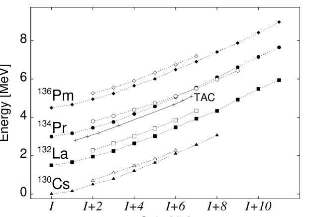
Pairs of close bands with the same parity are found in the neighboring odd-odd nuclei as well chiralsys ; bark ; starosta ; hecht ; hartley . Fig. 5 shows as examples the isotones ofPr75. The bands are close but do not merge. This means that the chirality cannot be broken in a static way as in molecules. There must be substantial tunneling between the left- and right handed configurations. As we discuss in the next section, the a weaker form of chirality may occur as a slow motion of the angular momentum vector into the left- and right handed sectors. The frequency of such a chiral vibration is less than 300 keV (cf. Fig. 5). In this respect, breaking of chiral symmetry is similar to breaking reflection symmetry by octupole deformation. The two branches of opposite parity do not completely merge into one rotational band (see e.g. octupole .
For most molecules tunneling between the two enatiomers is negligible; for complex molecules the tunneling time easily exceeds the age of the universe. We can separate the left-handed from the right-handed enantiomers (or other organisms do it for us) and can experiment with one specie. The turning of the polarization plane of light by organic sugar is a familiar example. The effect is caused by the chiral arrangement of the optical active atoms in the molecule. In nuclei, chirality is harder to demonstrate, because of the rapid motion between the left- and right-handed configurations. Therefore, one has to understand this motion. A microscopic description of this large amplitude motion is not yet available for the interpretation of the experiment. However, we may gain insight into the dynamics by further studying the particle-rotor model, in the context of which the possibility that rotating triaxial nuclei may become chiral was conceived chiral .
3 Dynamics of Chirality in the Particle-Rotor Model
The simplest chiral configuration is illustrated in Fig. 4. One high-j proton and one high-j neutron couple to a triaxial rotor. For the odd-odd nuclei in the mass 134 region, the high-j orbitals are . The generic case of a triaxial rotor with maximal asymmetry () and the irrotational flow relation between the moments of inertia was studied in chiral ; bark ; starosta .

Fig. 6 shows the result of such calculations. At the beginning of the lowest band the angular momentum originates from the particle and the hole, whose individual angular momenta are aligned with the s- and l-axes. These orientations correspond to a maximal overlap of the particle and hole densities with the triaxial potential, as illustrated in Fig. 4. A band is generated by adding the rotor momentum in the s-l plane (planar tilt). There is a second band representing a vibration of out of the s-l plane, which is generated by a wobbling of . This is a more precise description of the chiral vibration mentioned above. Higher in the band, reorients toward the i-axis, which has the maximal moment of inertia. The left- and the right-handed positions of separate. Since they couple only by some tunneling, the two bands come very close together in energy. This is the regime we called chiral rotation. The reorientation of , i. e. the transition from chiral vibration to rotation is well localized in the spectrum Fig. 6. It appears also in the higher bands at larger .
A more detailed picture of this transition emerges if we consider the classical orbits of the angular momentum vector . For a fixed value , the endpoint of is confined to the surface of the sphere
| (2) |
The energy of the triaxial rotor is given by
| (3) |
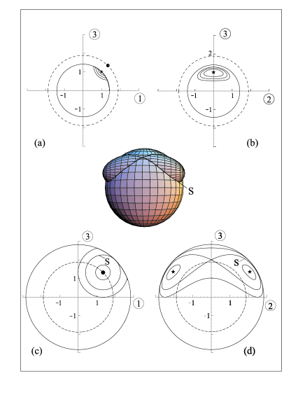
where 1, 2, 3 denote the s-, i- and l-axes, respectively. Further we assume that and have the same magnitude and are parallel to the s- and l-axes (cf. Fig. 4), and that they remain frozen in this orientation. In this “frozen alignment” approximation, the energy of the particle-rotor system, which is conserved, is given by (3) (up to a constant). Equation (3) defines an spheroidal energy surface on which the angular momentum vector has to end. The classical orbits of are given as the intersections of the angular momentum sphere and the energy spheroid. In Fig. 7 a typical set of classical orbits is plotted, where we introduce the dimensionless quantities and . Increasing the energy of the states for given , corresponds to increasing size of the spheroid. The symmetry axis of the spheroid is parallel to the 2-axis at . Its position defines a critical angular momentum . If , the axis lies outside the angular momentum sphere. As seen in the upper panel, the lowest energy correspond to the touching point of the sphere and spheroid, which is marked by the star. The lowest orbits revolve this point in the 1-3 plane. They are the chiral vibrations, which are seen as the lowest three bands in Fig. 6 for . The name alludes to the fact that the vector oscillates between the left- and right-handed sectors.
If , the axis lies inside the angular momentum sphere. As seen in the lower panel of Fig. 7, at the minimal energy, the energy spheroid touches the angular momentum sphere from inside at the two symmetric points marked by the stars. For somewhat larger energy, the spheroid penetrates the angular momentum sphere, which gives rise to two separate orbits around the two points of minimal energy. This case corresponds to static chirality or chiral rotation, where all three angular momentum components are non-zero. Fig. 6 shows a calculation for particles, i.e. and the critical angular momentum . Above this value, the two lowest bands quickly merge into a chiral doublet. The quantal tunneling smooths out the transition from the chiral vibrational to the chiral rotational regime. When is sufficiently larger than the critical angular momentum , there there are more than one orbit around the minima possible, which correspond to the excited doublets of bands in Fig. 6. These states are characterized by a wobbling motion around the two points of minimal energy. At still larger energy the front of the spheroid comes out of the sphere. The left-handed and right-handed orbits are no longer separated, i.e. we are back to the regime of only dynamical chirality without the characteristic doublets of bands. The energy of this transition corresponds to a special orbit, the separatrix, which is shown in the center of Fig. 7.
The static energy barrier between the left- and right-handed sectors is in the order of 100 for (cf. Fig.3 in chiral ). This seems very low. Nevertheless, the quantal calculation shows that the splitting between the bands is very small (cf. Fig. 6) and that the wavefunction is concentrated around the minima of the classical energy. Tunneling is determined by the ratio of the barrier height and the mass coefficient. The mass coefficient is small enough such that the tunneling through the low barrier is strongly reduced.
4 Predictions of chirality in various mass regions
Chirality becomes possible if high-j particles and high-j holes couple to a triaxial core. We have carried out TAC calculations in order to locate mass regions, where these conditions are met. Table 1 summarizes the results. The table shows only one representative nucleus for each region. Most TAC calculations have been carried out for the region around Pr75, which we discuss now. One can expect similar behavior in the regions around the other representative nuclei.
particle hole 35 44 9 0.19 26 43 65 13 0.21 14 59 75 13 0.18 26
particle hole 77 111 13 0.21 40 69 93 45 0.32 26
Both the experiment and the TAC calculations point to an island of chirality around and . In the chain, the shores seem to be and 51. The low- shoreline seems to be 72. The high- shore is not known yet. The center of the island is and . The TAC-barriers between the the left- and right handed sectors are in the order of 50- 100 . The Particle-Rotor calculations show that this leads to grouping into the chiral sister bands. However, for a quantitative estimate of the splitting one needs calculating the tunneling in a microscopic way, which we have not been able yet. Therfore, we only correlate the chiral TAC solutions with the appearance of pairs of bands, without trying to predict if they will be chiral vibrators or rotors.
The simplest chiral configurations appear in odd-odd nuclei, where a high-j particle and high-j hole couple to the triaxial rotor. Most of the experimental chiral sister bands in the mass 134 region have this structure. The positive parity orbits do not contribute strongly to the angular momentum . Combining the chiral high-j structure with one particle on such a spectator orbit gives a chiral configuration in an odd-A nucleus. As an example, TAC calculations predict chiral sister bands with the configuration in Nd75. Adding another spectator embeds the chiral skeleton into an even-even nucleus. TAC calculations give the chiral configuration in Nd76. For breaking the chiral symmetry, the particle and hole “legs” need not be of the same length, and they may be composed of more than one high-j orbital. As an example, we calculated the chiral configuration in Nd75. Zhu et al. nd135 found a pair of negative parity bands coming as close as 60 in this nucleus, which have this structure. Mergel et al. found a pair of negative parity bands in Nd76, which may be or, as suggested by the authors, .
| 67 | 68 | 69 | 70 | 71 | 72 | 73 | 74 | 75 | 76 | 77 | 78 | |
|---|---|---|---|---|---|---|---|---|---|---|---|---|
| 65 | ||||||||||||
| 64 | ||||||||||||
| 63 | S/CV | |||||||||||
| 62 | ||||||||||||
| 61 | L/CR | |||||||||||
| 60 | L/CR | L/CR | L/0 | |||||||||
| 59 | P/AC | 0/CV | L/CR | 0/CV | ||||||||
| 58 | L/0 | |||||||||||
| 57 | 0/CV | M/CV | 0/CV | |||||||||
| 56 | P/AC | |||||||||||
| 55 | 0/CV | S/CV | 0CV | |||||||||
| 54 |
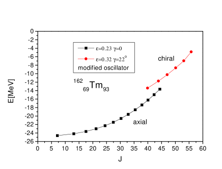
Much less TAC calculations have been carried out for the other regions in Table 2. The only experimental candidate for chiral sister bands is Rh59 rh104 . Strongly deformed triaxial shapes at high spin have been suggested for nuclei with and where evidence for the wobbling excitations has been found wobbler . The strongly deformed triaxial configurations contain the proton particle. For the lowest neutron numbers the hole becomes accessible and chirality a possibility. TAC calculations predict the existence of such a structure in Tm93. Fig. 8 shows that around spin 50 the chiral sister bands should approach the yrast line.
5 Conclusions
The quantal rotation of molecules has been the paradigm for the interpretation of nuclear rotational bands. However, for nuclei the relation between angular momentum and velocity is much more complex than for molecules. Nuclei contain nucleons on orbits with large angular momentum, which is kept constant by quantization. Due to the presence of these micro-gyroscopes the axis for uniform rotation (the angular momentum vector ) can take any direction with respect to the density distribution. The chiral symmetry is broken if does not lie in one of the three mirror planes planes of the triaxial density distribution. Chirality appears in geometric arrangement of atoms or chemical groups in in molecules. Chirality is also a dynamical property of mass-less elementary particles. The new example of chirality of rotating nuclei results from the combination geometrical (triaxial shape) and dynamical (orientation of ) features.
Chiral rotation manifest itself as a pair of nearly identical -bands with the same parity. Tunneling between the left- and right-handed configurations causes an energy splitting between the chiral sister bands. A weaker form chirality are the chiral vibrations, which are slow oscillations of between the left- and right-handed configurations. They show up as an equidistant sequence of -bands, separated by the (small) vibrational energy.
Microscopic tilted axis cranking calculations predict chirality in various mass regions. There is some systematic experimental evidence for chiral sister bands in odd-odd nuclei around mass 134, which is one of the predicted regions.
References
- (1) S. Frauendorf, and Meng, J., 1997, Nucl. Phys. A 617, 131 (1997)
- (2) S.Frauendorf, Nucl. Phys. A557, 259c (1993)
- (3) Kerman, A.K., and Onishi, N., Nucl. Phys. A 361, 179 (1981)
- (4) Frisk, H., and Bengtsson, R., Phys. Lett. 196B, 14 (1987)
- (5) Bengtsson, R., and Frauendorf, S., Nucl. Phys. A327, 139 (1979)
- (6) V.I.Dimitrov, S. Frauendorf, and F. Dönau, Phys. Rev. Lett. 84, 5732 (2000)
- (7) C. Petrache et al. , Nucl. Phys. A597, 106 (1996)
- (8) K. Starosta, et al, Phys. Rev. Lett. 86, 971 (2001)
- (9) R. A. Bark et al. Nucl. Phys. A 691, 577 (2001)
- (10) K. Starosta et al., Nucl. Phys. A682, 375c (2001)
- (11) A. A. Hecht et al., Phys. Rev. C63, 051302(R) (2001)
- (12) D. J. Hartley et al. Phys. Rev. C64, 31304(R) (2001)
- (13) P. A. Butler, and W. Nazarewicz, Rev. Mod. Phys. 68 (1996) 349.
- (14) E. Mergel et al. Eur. Phys. J. A, in print
- (15) S. Zhu, et al. private communication
- (16) see K. Koike et al., lecture at this conference
- (17) see G. Hagemann, L.L. Riedinger et al., lectures at this conference