A Compact Solid State Detector for Small Angle Particle Tracking
Abstract
MIDAS (MIcrostrip Detector Array System) is a compact silicon tracking telescope for charged particles emitted at small angles in intermediate energy photonuclear reactions.
It was realized to increase the angular acceptance of the DAPHNE detector and used in an experimental program to check the Gerasimov-Drell-Hearn sum rule at the Mainz electron microtron, MAMI.
MIDAS provides a trigger for charged hadrons, p/ identification and particle tracking in the region .
In this paper we present the main characteristics of MIDAS and its measured performances.
, , , , , , , ,
, ,
,
1 Introduction
An experimental program has been started at the MAMI tagged photon beam facility to verify the Gerasimov-Drell-Hearn (GDH) sum rule. A detailed description of the physical motivations are reported in refs. [1, 2, 3, 4]. The experiment requires the measurement of the total absorption cross section of circularly polarized photons on longitudinally polarized nucleons over a wide range of energy. The GDH sum rule is related to the difference of the two helicity dependent cross sections, considering target and beam spins parallel and antiparallel.
As a consequence a large angular and momentum acceptance detector is needed to reduce extrapolations and then minimize systematic errors in the total cross section evaluation.
The DAPHNE detector [5] already meets most of the above requirement, covering 94% of the total solid angle (; ). However in order to increase the acceptance in the angular region an upgrade of the detector was necessary. Since the DAPHNE structure includes a mechanical frame which shadows particle transmission in the region , the extension of the acceptance into this range required a set-up inside the frame. For angles beam-halo interference is a problem unless the detector is placed far downstream of the target.
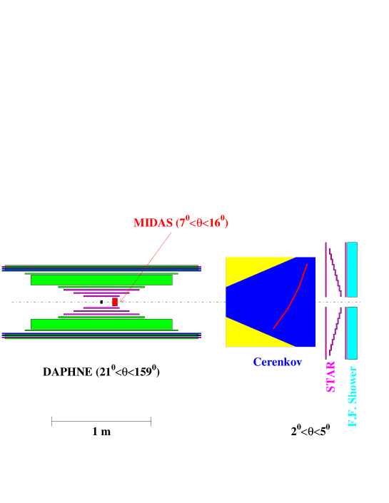
Thus the forward-angle system has two components: MIDAS, described here and in refs. [6, 8], covers the region and is placed deep inside the DAPHNE frame, close to the target, while the STAR detector and a scintillator-lead device [9] are placed externally to the frame covering the region . Between the two devices an aerogel and N2 gas Čerenkov detector enables electron detection with a threshold of about 15 MeV and an efficiency 99%. Its anti-coincident signal is used to suppress electromagnetic background from the trigger. The full experimental set-up is shown in Figure 1.
2 Detector design
The volume around the target was very limited, so we decided to use silicon detectors in order to obtain a compact geometry for MIDAS.
MIDAS includes two parts (see Figure 2): a tracking section consisting of two annular double sided silicon detectors (V1 and V2) and an annular silicon/lead sandwich (Q1, Pb, Q2, Pb, Q3) for energy measurement.
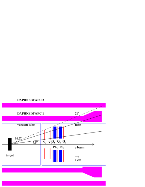
A central hole allows the primary beam to go through.
The p-side of the tracking detectors is divided into 48 concentric rings, while the n-side is segmented into 16 radial sectors. The signals are carried out by a flexi-rigid cable consisting of 5 overlapping layers each screened by a grounded wire-netting structure.
The remaining detectors Q1, Q2 and Q3 are single sided with the p-side segmented into 4 radial sectors (quadrants).
All detectors were manufactured by Micron Semiconductor Ltd, UK. Their main geometrical parameters are listed in table 1.
| Tracking Detectors | Quadrant Detectors | |
|---|---|---|
| Thickness | 1000 m | 1000 m |
| Geometry | Annular Ring | Annular Ring |
| inner radius | 11 mm | 14 mm |
| outer radius | 35 mm | 43 mm |
| Type | Double sided | Single sided |
| p side | 48 rings | 4 sectors |
| n side | 16 sectors | - |
The detectors and the lead absorbers were mounted inside an Aluminum tube fitted into the forward hole of the DAPHNE detector. The detector signal cables exit from the downstream opening of the tube leaving the region free for the particle transmission towards the other forward devices.
The tube was closed at both ends by 25 m thick Aluminum windows and supplied with an Argon flow of a few /h to ensure that the detectors current is stable and does not depend on atmospheric impurities or humidity.
3 Principle of operations
GEANT simulations were used to optimize the geometrical set-up by taking into account the experimental conditions at MAMI energy. MIDAS provides the following functions:
-
1.
charged-hadron triggering;
-
2.
charged-particle tracking;
-
3.
discrimination between e±, and p
3.1 Hadron trigger
Two trigger conditions were implemented to detect protons and pions with the minimum background contamination.
The most important source of background is due to electrons (and positrons) from pair production and Compton scattering processes occurring in the experimental target. The double lead sandwich, whose total thickness corresponds to 3 radiation lengths, was designed to absorb most of these electrons.
On the contrary, almost all the pions and high energy protons at forward angles are completely transmitted, giving a signal from all detectors. Therefore a good trigger for high energy hadrons was obtained by the coincidence of the 3 quadrant detectors Q1, Q2, Q3.
The low energy protons stopped inside MIDAS produce a Q1-Q2 coincidence. These particles have a large energy loss rate, so that in this case detection thresholds could be set high enough to cut most of the electromagnetic background.
Simulations showed that the above triggers allow the detection of protons and pions with energies 60 MeV and 50 MeV respectively, while electromagnetic background is suppressed with an efficiency of about 99%.
The remaining background comes mainly from pair production processes. In most of the cases only one of the two electrons enters MIDAS, while the other is emitted at a very small angle and then detected by the Čerenkov counter (see Figure 1). These events were eliminated by requiring an anticoincidence between the Čerenkov signal and the MIDAS trigger. With this configuration the background rate was reduced by about 3 orders of magnitude and kept comparable to the pion rate. Further suppression was performed off-line as discussed in Section 5.2.
3.2 Tracking
Particle tracking is performed by the V1 and V2 detectors. A charged particle passing through one of these detectors produces a signal from a single ring and a single sector.
The intersection between the hit ring and the hit sector determines the impact point of the particle on the detector. Then two detectors allow the complete reconstruction of the particle trajectory.
The polar and azimuthal angular resolution depends on the ring pitch and on the sector opening angle respectively, which were chosen to give and .
3.3 Particle identification
Most of the protons and pions entering MIDAS have momenta 1 GeV/c, so they can be identified by measuring their . In particular we apply the Range Method, previously developed for DAPHNE [7] and adapted to MIDAS geometry. A particle entering V1 can cross several layers before stopping or going through Q3 if its energy is high enough, the signal from each detector giving the particle along its path.
In the Range Method we use the Bethe-Bloch equation to calculate the mean energy loss of a given particle type (proton or pion) in the different MIDAS layers, as a function of the particle kinetic energy. Then a Least Squares Fit is used to determine the kinetic energy value which minimize the difference between the measured and calculated values of the samples. The analysis of the distribution of the fit allows the identification of the particle.
4 The electronics
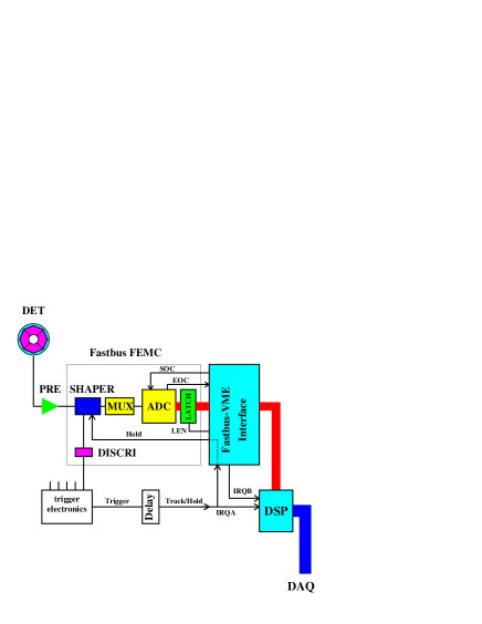
A block diagram of the electronics is shown in Figure 3. A detailed description can be found in ref. [8].
The silicon detectors are biased by a CAEN SY527, system remotely controlled via VME.
The readout electronics is based on Fastbus module FEMC described in refs. [10, 11]. These modules receive the differential signals from the preamplifiers and provide the shaping, the track & hold, the multiplexing and the digitization of the signals. There are four FEMC modules used in the electronics set-up, each module of 80 channels divided into 5 groups (rows) and each channel is equipped with a hybrid shaper, consisting of a (RC)2CR filter. It is followed by a hold circuit allowing the 80 signals to be multiplexed and serially digitized by a single 12-bit ADC.
After the first shaping stage a signal for trigger logic purposes is output. A double discriminator circuit allows to set two different threshold levels.
Data from the ADC’s are read and decoded into an interface, which contains control logic and then stored into a buffer memory under the control of a digital signal processor (DSP), Motorola type DSP56001 [12, 13, 14]. These data can be transfered to a host computer either via the VME bus or via the serial port of the DSP.
The first method, being faster, was used in the experimental data taking in which a master VMEbus computer handles the readout of the different sections of the whole apparatus. The second method was adopted to test MIDAS independently from the rest of the experimental apparatus.
5 Tests and performances
A series of runs at the MAMI tagged-photon beam facility allowed the set-up of the entire apparatus. Photoreactions induced on a Hydrogen target were used to test the response of the different detector sections.
In particular the response of MIDAS to pions and protons was studied using the double pion photoproduction reaction .
A clean sample of events with negligible background was obtained by a triple coincidence, detecting 2 charged particles in DAPHNE and one particle in MIDAS. Then two cases are possible:
-
1.
the two pions are detected in DAPHNE and the proton in MIDAS
-
2.
the proton and one pion are detected in DAPHNE and the other pion in MIDAS.
The reaction kinematics is completely defined when the emission angles and of both particles detected in DAPHNE are measured, together with one of their energies.
In both of the above cases it was possible to calculate precisely the energy and direction of the third particle by using DAPHNE only, since this detector has very good angular and momentum resolutions.
5.1 Angular resolution
The angular resolution of MIDAS was obtained by comparing the measured and angles of the forward emitted particle with the values calculated by kinematics on the basis of the DAPHNE measurements. The distributions of the difference between these two values are shown in Figure 4.

The contributions of the uncertainties induced by the DAPHNE resolutions to the distributions widths are and . They can be easily subtracted to give the overall MIDAS resolution of and .
5.2 Energy calibration and particle identification
Most of the selected pions entering MIDAS are relativistic and release almost the same energy (0.4 MeV) in each silicon detector. On the contrary proton energy losses range from about 0.5 MeV to several MeV, allowing the study of the response of the detectors at different energies.
The Bethe-Bloch formula was used to calculate the energy released by protons, of a given incident energy, in each detector. The correlation between the pulse height and the calculated energy loss determined the detector calibration.
The response of the Q1 detector to 125 MeV monoenergetic protons is shown in Figure 5.

The mean energy loss is 1.25 MeV, so its measured distribution width is 34 % (FWHM). The energy loss width of the same detector Q1 as a function of the proton energy is shown in Figure 6.

The distribution width is completely dominated by straggling, due to the small detector thickness. Straggling is the most serious limitation in particle identification using techniques.
However MIDAS provides measurements with enough resolution to discriminate protons and pions over most of the energy range covered in the experiment.
As an example, the stopping power of particles measured by Q3 is shown in Figure 7 as a function of the particle momentum. The pion and proton regions are clearly separated and discrimination is possible up to a momentum MeV/c.

The Range Method (RM) was used to obtain particle discrimination and energy reconstruction, as described in Section 3.3. The fit procedure was applied to the selected particles and a cut on the distribution was established in order to have good proton identification efficiency and minimum contamination of pions. Pion contamination, estimated by counting pions fulfilling the fit condition for protons, is significant only at high energy (3% for protons above =500 MeV/c.
The proton energy resolution was obtained by comparing the value calculated by kinematics with that reconstructed by the RM. The difference of the two for protons with kinetic energy around T105 MeV is shown in Figure 8. The curve is a gaussian fit whose parameters are reported in the upper box of the plot. The width of the distribution is 6 MeV which corresponds to a kinetic energy resolution 14% (FWHM).

The pion energy cannot be reconstructed with the RM because the stopping power of these particles is nearly independent of energy. In addition, the separation between pions and the residual electromagnetic background, discussed in Section 3.1, cannot be fully achieved by . However electrons and positrons, producing a shower in the lead absorbers, exhibit an energy loss spectrum different from pions, as shown in Figure 9. In this case the electron sample was obtained by requiring a coincidence between the Čerenkov signal and MIDAS, in order to detect e+e- events.

It turns out that we can reject about 40% of electrons while only loosing 10% of pions by selecting particles with an energy loss E0.6 MeV in a single detector. The same condition, applied to all the detector Q1, Q2 and Q3, produces the suppression of 70% of electrons while loosing 20% of pions.
6 Conclusions
The MIDAS device meets the main needs of the GDH experiment for which it was build.
The measured angular resolution ( and ) are in reasonable agreement with the expected values (see Section 3.2) with discrepancies attributable to multiple scattering.
The Range Method analysis provides a powerful tool to identify protons with 3% of pion contamination and to measure their energy with good resolution (14% at T=105 MeV) by the simultaneous use of all the available measurements of the particle energy losses.
The e± background was suppressed in the trigger logic by 3 orders of magnitude and further reduced off-line of 70% by applying a cut on the energy loss spectra. Under these conditions the background contamination to pion count rate is still about 50%. This value is acceptable, since the main goal of our experiment is the measurement of the hadronic reaction asymmetry and electromagnetic processes give a net null contribution to it. On the other hand the background contamination in the small angular region of MIDAS does not significantly increase the statistical error of the measurement.
References
- [1] J. Ahrens et al., Experimental check of the Gerasimov-Drell-Hearn sum rule, MAMI proposal A2/2-93
- [2] J. Ahrens et al., Helicity dependence of single pion photoproduction on the proton, MAMI proposal A2/2-95
- [3] J. Ahrens et al., Helicity dependence of double pion photoproduction on the proton, MAMI proposal A2/3-95
- [4] J. Ahrens et al., Helicity dependence of single and double pion photoproduction and the GDH sum rule on the neutron, MAMI proposal A2/1-97
- [5] G. Audit et al., Nucl. Instr. and Meth. A301 (1991), 473
- [6] A. Panzeri, Tesi di Laurea, Università di Pavia (1996)
- [7] A. Braghieri et al., Nucl. Instr. and Meth. A343 (1994), 623
- [8] S. Altieri et al, INFN/TC-98/30, 30-10-1998; internal report
- [9] M. Sauer et al., Nucl. Instr. and Meth. A378 (1996), 143
- [10] G. Barichello et al., Nucl. Instr. and Meth. A254 (1987), 111
- [11] I. Lippi et al., Nucl. Instr. and Meth. A286 (1990), 243
- [12] Acquisizione VME per la scheda di readout FEMC, INFN sezione di Pavia, Servizio Elettronico; internal report
- [13] CPU DSP56 and DSPbug 4.1, INFN sezione di Pavia, Servizio Elettronico; internal report
- [14] DSP56001 24-bit Digital Signal Processor User’s Manual, Motorola Inc