A high-precision polarimeter
M. Hauger, A. Honegger, J. Jourdan, G. Kubon, T. Petitjean,
D. Rohe, I. Sick, G. Warren, H. Wöhrle, J. Zhao
Dept. für Physik und Astronomie,
Universität Basel,
CH-4056 Basel, Switzerland
R. Ent, J. Mitchell,
Jefferson Laboratory
Newport News, VA, 23606, USA
D. Crabb, A. Tobias, M. Zeier, B. Zihlmann
Dept. of Physics, Univ. of Virginia
Charlottesville, VA, 22901, USA
Abstract
We have built a polarimeter in order to measure the electron beam polarization in hall C at JLAB. Using a superconducting solenoid to drive the pure-iron target foil into saturation, and a symmetrical setup to detect the Møller electrons in coincidence, we achieve an accuracy of 1%. This sets a new standard for Møller polarimeters.
PACS: 29.25.Pj, 29.27.Hj, 34.80.Nz, 33.55.Fi
1 Introduction
Today, electron scattering experiments often involve the use of high energy (GeV) polarized electrons. Recent examples are measurements of the spin structure of the nucleon via and deep inelastic scattering[1, 2], or measurements of the charge form factor of the neutron via neutron knockout experiments ( on or [3, 4]. Such experiments are becoming increasingly more practical as electron sources providing beams of high intensity and high polarization [5] become standard equipment at the various electron accelerator laboratories.
For these experiments with polarized electrons, one needs polarimeters to measure the polarization of the high-energy beam. Standard methods are based on Compton () or Møller ( ) scattering. For these processes the analyzing power can be accurately calculated, so a measurement of the polarization asymmetry of the cross section yields the beam polarization once the polarization of the photon or the -target is known. Compton scattering in general leads to rather low rates, thus Compton polarimeters are preferably used in connection with large electron beam intensities (storage rings) [6, 7]. Møller scattering allows for much larger rates, and therefore can also be used for cases where the beam intensity is low, such as required in connection with cryogenic polarized targets which typically are limited to beam currents 100nA. The polarimeter we describe in this paper belongs to the Møller scattering category[8, 9, 10], and has been built in connection with experiments using polarized cryogenic and targets at JLAB.
Møller polarimeters are based on scattering. Since this is a pure QED process, its cross-section can be calculated to very high precision. For longitudinally () polarized beam (polarization parallel to the z-axis) and target () electrons, the cross-section is expressed in the centre of mass (c.m.) frame as:
| (1) |
where the unpolarized cross-section is given by at high energy, and the analyzing power by . One can effectively measure the beam polarization by comparing the cross-section asymmetry for beam and target spins aligned parallel and anti-parallel:
| (2) |
At 90 degrees (c.m.), the analyzing power is large, , and so is the cross-section, =17.9 fm2 sr-1. Further, these quantities are energy independent for large .
The expressions used in eqn. 1 follow from the lowest order diagrams of this process. A calculation has been performed for all diagrams to order [11], and although a significant impact is found for , a negligible effect is found for .
Despite the large analyzing power of –7/9, Møller scattering is not easy to exploit. In ferromagnetic -targets, only 2 of the typically 25 electrons are polarized, leading to an effective target polarization of only 8%. The reliable determination of the beam polarization requires tight control over systematic errors, and high statistics.
In order to achieve a precision measurement of the beam polarization, certain limitations have to be overcome. In earlier polarimeter designs [8, 9], three factors contributed significantly to the overall error: achievable statistics, uncertainties due to background contributions (mainly Mott scattering), and the error in the determination of the target electron polarization . Up till recently, no system had obtained an uncertainty better than 3% [12] and many were much worse. Furthermore, almost all work neglected the influence of the atomic motion of the target electrons on the effective analyzing powers, an effect only recently identified by Levchuk [13].
In the present polarimeter we reduce the background contribution uncertainty by using a coincidence detection system; this allows us to eliminate the dominating background from Mott scattering which does not lead to coincident pairs. To enhance the statistical precision without requiring long data acquisition time, we employ a large acceptance for detection of the scattered electrons. Using a large acceptance at the same time allows us to reduce the influence of the atomic motion of the electrons in the Møller target on the effective analyzing powers Azz, to the point where it easily can be corrected for. In order to eliminate the then dominant error from the uncertainty in the polarization of the electrons in the magnetized ferromagnetic foil we use a novel approach [14, 15] which employs foils made from pure iron, magnetized out of plane to saturation using a 4T field. For pure iron in saturation, the electron polarization is known with great accuracy.
In the present paper, we describe the polarimeter built and used in hall C at JLAB. We show that with the approach taken we are able to reduce the uncertainty to below the 1%-level.
2 Set-up
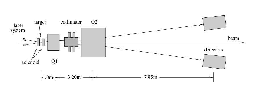
The general layout of the polarimeter is shown in fig.1. The incoming electron beam of energy of (typically) 1 – 6 GeV is focused onto the Møller target. This target is made from a thin foil of pure iron oriented perpendicular to the electron beam, and which is magnetized using a superconducting solenoid producing a 4T field in the direction of the beam. The scattered electron and the recoiling target electron, which emerge in the horizontal plane at angles between 1.83 and 0.75 degrees in the laboratory, are focused using a first quadrupole Q1. The desired scattering angles are selected by a set of collimators. The electrons then are defocused using the quadrupole Q2, and detected in coincidence using two symmetrically placed hodoscope counters and lead-glass detectors. We below describe the individual elements in more detail.
Target
The guiding principle for the choice of the target has been investigated by deBever et al [15]. As a source of polarized target electrons we use pure iron. The polarizable electrons, two of the 25 per atom, are polarized using a 4T field in beam direction, perpendicular to the iron foil. This setup differs in a number of ways from the standard one involving foils of an iron alloy, oriented at 20∘ relative to the beam and polarized in-plane using a magnetic field of the order of 0.01T.
-
•
The spin polarization for pure iron in saturation is known with excellent precision [16]. This precision basically comes from the fact that, in saturation, the properties of an isolated iron atom and the atoms in a foil are the same. In this case the spin polarization can be measured using large pieces of iron; measurements of the magnetization together with measurements exploiting the Einstein-deHaas effect allow to separate the spin contribution from the orbital contribution to the magnetization, the latter being the main source of uncertainty for alloys. The spin polarization for pure iron has been measured to about 1/4% accuracy [16].
-
•
Saturating a pure iron foil out of plane comes at the expense of requiring a high magnetic field, 4T. Such fields today can be produced easily using small superconducting split coils, and the longitudinal B-field has little effect on the incoming and scattered electrons.
-
•
Since the foil is saturated brute-force no delicate absolute measurements of the foil magnetization (polarization) using in-situ pickup coils are required.
-
•
Under conditions of high beam current, leading to heating of the iron target, the decrease in foil polarization can easily be measured using a Kerr apparatus [15]. (This Kerr apparatus has been built and tested, but was not employed in the first experiment described here as the currents used were very low).
-
•
The lack of need to measure the foil magnetization allows us to use a large dynamical range of foil thicknesses, as governed by the beam intensities used by the main experiment. At the same time, rotation of the foil to spread the heat could easily be performed if much larger beam intensities should be required.
-
•
Since the target is perpendicular to the beam, the usually needed corrections for the cosine of the angle between target polarization and beam direction are not needed; this also eliminates the measurements with symmetrical target orientation often required to eliminate uncertainties in the target angle when dealing with slightly warped target foils.
The Møller target is placed on a target ladder which, by remote control, can be moved horizontally into the beam. This target ladder carries foils of several different thicknesses, together with a viewing screen to check the alignment of the beam.
Solenoid
The superconducting split-coil solenoid used to polarize the iron target was purchased from Oxford, and is run using an IPS120-10 power supply. The split coils produce a maximal field of 4T. The coils have a 6.7cm diameter bore for the beam, and a sideways access of 3.5cm width and 7.6cm height for the target ladder. The liquid nitrogen and helium required for operation of the solenoid is supplied by the hall-C cryosystem.
Magneto-Optical System
We use a two-quadrupole system to increase the angles of the scattered- and recoil electrons such as to be able to place the detectors at a reasonable distance from the beamline. The quadrupoles deflect the Møller electrons, without affecting the incident beam which goes through the center of Q1, Q2 and is virtually undisturbed given its low emittance. Besides the increase of the separation between Møller electrons and beam, Q2 also provides, in combination with the collimator, an energy analysis of the Møller electrons. This greatly reduces backgrounds.
Studies of various layouts have shown that a system with two quadrupoles is much more flexible than the usual one-quadrupole or magnet plus septum systems; for the entire energy range of interest, 1 – 6 GeV, the Møller electrons can be imaged onto the detectors without any change in geometry. The main function of Q1 occurs at low incident electron energy. There, the Møller electrons for 90∘ CM-angle are produced at comparatively large angles in the laboratory system, and Q1 focuses these electrons into the acceptance of Q2. At large electron energy, Q1 has virtually no effect. With the two-quadrupole setup, Q2 can be placed at a larger distance from the target, thus maximizing the overall deflection of the Møller electrons.
This two-quadrupole system allows us to maintain, over the entire energy range of 1 – 6 GeV, an image of the 90∘ electrons of elliptical shape with an axis-ratio of 2 at the location of the detectors. With such an image, a clean selection of coincident electrons using slits in front of the detectors, and a useful measurement of the scattering angles using the hodoscope is possible. The optimal tuning of Q1, Q2, calculated using a MC simulation of the setup, is given in fig.2.


Adjustable collimators
Møller scattering produces a spectrum of scattering angles; for polarization measurement, angles around 90∘ in the CM system are of particular interest given the maximal analyzing power of 7/9. At the same time, Mott scattering (from nuclei) produces a large flux of scattered electrons at small scattering angle, which one would like to suppress as far as possible.
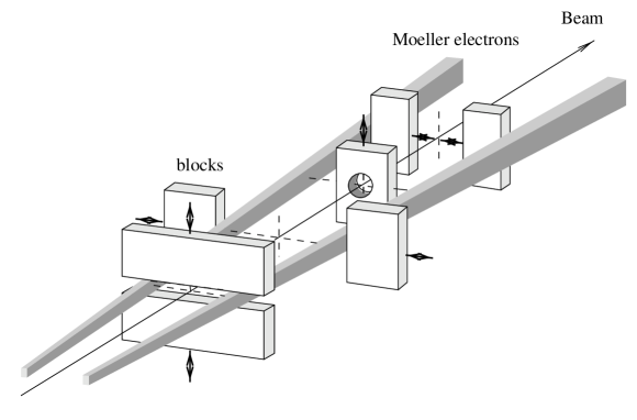
The collimator system has been designed to select a range of scattering angles, and to cut off electrons at both smaller and large angles. This is achieved by a set of six moveable jaws (see figure 3). A seventh collimator with fixed acceptance in the center eliminates the electrons that could pass on the small-angle side of the inner horizontal collimator. When the polarimeter is not in use, these collimators are all removed by remote control.
The collimator jaws are made from densimet, 8cm thick (22 radiation lengths). With this thickness, all unwanted electrons are removed, or loose so much energy that they can no longer give large enough a signal in the lead-glass total absorption counters.
The selection of scattering angles by the collimators is only a rough one, and is made such as to be less constraining than the selection made by the slits in front of the hodoscope. The main function of the collimators then is to stop electrons which otherwise could hit the vacuum enclosure and get, through uncontrolled pathways, to the detectors.
The collimators are placed before Q2, such that the energy-analysis performed by Q2 removes eventual low-energy electrons that are produced in the jaws.
Slits
In front of the detector package, two slits define the actual angular acceptance of the polarimeter. These slits are about 12cm wide in horizontal direction, and have a tapered opening of 2cm – 3cm in the vertical direction, such as to select a constant bin in out-of-plane angle . One of the slits has a somewhat larger acceptance, in order to insure that the other slit is the one that sets the angular acceptance. Simulations have shown that this arrangement minimizes the Levchuk effect (see below).
The slits are made from lead, and are 9 radiation lengths thick.
Detector package
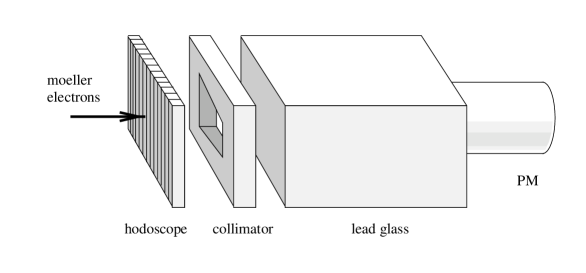
The main detectors identifying the Møller electrons are the lead-glass total absorption counters. The blocks have dimension of 20x14x23cm3 in order to contain the entire shower produced by the Møller electrons, and are made from SF2 lead glass. Measurement of the amplitude of the light signal, observed with one 5” photo tube for each block, provides a discriminating signal for the presence of an electron of the appropriate energy. Measurement of two such electrons in coincidence provides a virtually background-free identification of Møller electron pairs.
For the actual measurement of the beam polarization, only the coincidence rate of the total absorption counters is used. The number of coincidences can be measured over a very large dynamical range of the rate with very little dead time, and minimal investment in terms of electronics.
In front of the lead-glass total absorption counter, two hodoscopes provide information on the location of the coincident electrons. This information is used during the setup of the polarimeter mainly, it need not be recorded during the actual measurement of the polarization.
The hodoscopes have 14 horizontal channels each. Each channel consists of a bar of scintillator, 8x12mm2 in cross section and 80mm high, viewed by a 8mm diameter photomultiplier. Two of the channels, number 3 and 12, are vertically split into two halves, such as to also get information on the vertical tuning. The information from the hodoscopes is read out only once the pair of lead-glass detectors has identified a coincident Møller pair.
In front of the hodoscopes, we have placed a layer of lead, 1cm thick. This serves to remove low-energy background which could lead to high count rates in the hodoscope, and it leads to the development of a shower which causes an increased energy deposit in the hodoscope.
Electronics
The main information provided by the polarimeter is the rate of the two lead-glass detectors measured using two photo multipliers, fast *5 amplifiers, clipping of the analog signals and fast discriminators (5 and 10ns pulse width). Prompt and delayed Left-Right (L-R) coincidences are registered during a run using VME scalers. The scalers are read out upon completion of the run or a flip of the electron polarization at the source.
The analog signals from the hodoscopes are sent through ECLINE discriminators and the pattern of both hodoscopes is registered for valid L-R coincidences using fast CAMAC memories (LeCroy 4302) capable of storing 16k events. During data taking runs, the hodoscope information is recorded for a small fraction of the L-R coincidences only, as it only serves as a check of the proper alignment.
Control
The entire Møller system including the cryogenics needed for the solenoid is controlled from two Graphics User Interfaces (GUI). The GUIs use the Experimental Physics and Industrial Control System (EPICS), a set of software tools and applications jointly developed by Los Alamos National Laboratory and Argonne National Laboratory [17]. The control programs communicating with the hardware over various interfaces running on front-end computers in VME crates. The interface to the backend user program or GUIs is the EPICS data base.
3 Results
We have carried out a number of measurements of the beam polarization, accompanied by a number of sensitivity tests. Some of the results are described below.
For the measurements carried out, we have used beam currents of typically 1A; the main experiment ran usually at 100nA. In tests the polarimeter has been successfully used at currents up to 8A. As Møller target, we used pure iron foils, 4 and 10 m thick.
Tuneup for the polarization measurements involved focussing of the beam onto the polarimeter target, which was located some 30m upstream of the spectrometers used for the main experiment. Using the viewers on the polarimeter target ladder, and another viewer placed 12m upstream, the position and direction of the incoming electron beam were adjusted, to 0.5mm. For some of the actual measurements, the fast rastering of the electron was then turned on, leading to a beam distributed over 0.5 or 1mm. In order to keep the beam centered downstream of the polarimeter after ramping up the fields of the solenoid and Q1, Q2, only minor adjustments of steering coils downstream of the polarimeter were needed.
The beam current was measured using RF cavities with high bandwidth and signal to noise ratio. The cavities are temperature stabilized to 0.3∘. The 1.497 GHz signal from the cavity is down-converted to 100kHz and subsequently converted into a DC-voltage which is proportional to the beam current. The DC Voltage goes to a 1MHz voltage to frequency converter, the output of which is integrated using a VME scaler. An absolute calibration of these cavities is obtained using an independent Unser monitor [18]. In several calibration periods two-minute runs with alternating periods of beam-on and beam-off are made at various beam currents. The beam off periods allow to measure the zero offset of the cavity and Unser monitor, the comparison of the Unser monitor and the cavities during beam-on yields the gains of the cavities.
During the data reduction, we have also analyzed the asymmetry of the charge accumulated for the two polarization states. This asymmetry was usually below 5 10-4. This leads to negligible errors in the polarization measurements due to eventual non-linearities of the current monitors, or zero-offsets. The polarity of the electron polarization was flipped once a second at the polarized source.
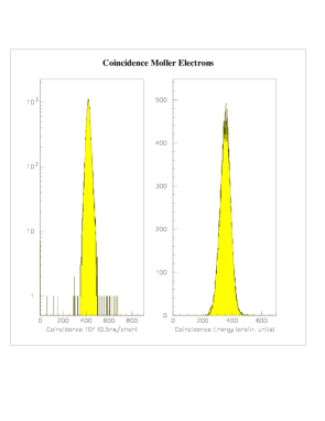
As pointed out above, the main observable used for the determination of the beam polarization is the coincidence rate between the two lead-glass detectors. Fig.5 shows the spectrum of the time difference between the signals in the two detectors registered in sampling-mode in parallel. Under the conditions used for these measurements, the rate of accidental coincidences is obviously very small. The accidentals have been measured via a delayed coincidence, and subtracted.
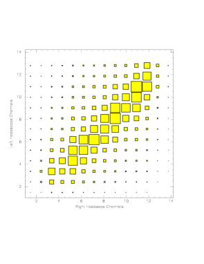
In fig. 6 we show the distribution of events on the hodoscopes. The coincidence signals of interest populate the region of the diagonal, as expected for Møller scattering. The higher density of events towards the upper left-hand side reflects electrons that have lost energy due to radiative processes.
Improper tuning of Q2 can lead to a shift of the ridge away from the diagonal, a shift that is very easy to observe. The same is true for a mistune of Q1. A combined mistune of Q1 and Q2 leads to a shift along the diagonal. This can easily be observed by looking at the projection of the events onto the diagonal, see fig. 7. Such a mistune leads to a shift of the
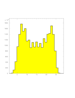
minimum along the diagonal.
We have investigated the effect of a mistune of Q1, Q2 both via our Monte-Carlo simulation, and experimentally. In fig. 8 we show the change of the analyzing power observed when detuning the current of Q1 (Q2) by 2%(1%).

The observed sensitivity to the tuning of Q1, Q2 corresponds to the one expected from the simulation.
The time needed to acquire the statistics for precise measurements of the beam polarization is quite short. At 70% beam polarization as available during the runs used here it took 5 minutes to acquire the 9106 events needed to get a 1% relative uncertainty on the beam polarization. If needed, this time could be further shortened by using iron foils thicker than 10m.
We have found that tuning of the polarimeter is very straightforward. Potential errors in the set-up are detected easily, and corrections to be applied to the raw asymmetry (accidentals, dead time, …) are very small.
4 Sensitivity studies
The uncertainty of the polarization measurement is determined by the knowledge of the foil polarization, the statistical error on the count rate asymmetry, and various errors in the set-up and tuning of the hardware.
We have described in the introduction the basic principle of our polarimeter which was chosen such as to minimize the usually dominating error of the spin polarization of the atomic electrons. For pure iron, the spin polarization in saturation is known to 0.25%.
The uncertainties due to the various potential mis-tuning of different elements have been minimized in the design, by selecting a set-up which is left-right symmetrical, and exploits the Møller angular distribution around the symmetry point at 90∘ CM angle. As a consequence, all errors from geometry and tuning drop out in first order; only quadratic terms come in. This makes the polarimeter very insensitive to the various errors.
In order to explore the sensitivity, we have used the Monte-Carlo simulation program. In table 1 we quote for the various potential sources of error due to alignment of the incoming beam, alignment of the quadrupoles, mistune of the quadrupoles and uncertainty in the angle-acceptance defining slits. We also quote the effect of the uncertainty due to imperfect corrections for the Levchuk effect (motion of the atomic electrons) and multiple scattering of electrons in the foil.
| source | uncertainty | effect A |
|---|---|---|
| beam position x | 0.5mm | 0.15% |
| beam position y | 0.5mm | 0.03% |
| beam direction x | 0.15mr | 0.04% |
| beam direction y | 0.15mr | 0.04% |
| current Q1 | 2% | 0.10% |
| current Q2 | 1% | 0.07% |
| position Q2 | 1mm | 0.02% |
| multiple scattering | 10% | 0.12% |
| Levchuk effect | 10% | 0.30% |
| position collimator | 0.5mm | 0.06% |
| target temperature | 50% | 0.05% |
| direction B-field | 2∘ | 0.06% |
| value B-field | 5% | 0.03% |
| spin polarization in Fe | 0.25% | |
| total | 0.47% |
For the alignment of the beam, we quote the effect of uncertainty due to the beam position measurement. For the placement of the elements such as quadrupoles and collimators, we use an uncertainty which is much larger than the uncertainty quoted by the surveyors. For the uncertainty in the focal strength of Q1, Q2 we use as values the deviations that can easily be recognized when looking at figs. 6,7.
For the Levchuk effect, we use 10% of the change in the analyzing power obtained when turning off the Levchuk effect entirely. The Levchuk effect has been calculated using the program of [19] adapted to our conditions; it amounts to 3.03% at 4GeV, and similar values over the entire energy range. The Levchuk effect in our case leads to a small change of the analyzing power as a consequence of the large acceptance of the polarimeter, and the fact that we use a slightly asymmetric collimator for the two sides. We give the calculated value a 10% uncertainty in order to account for potential uncertainties in the atomic wave functions employed in the calculation.
For the multiple scattering effect, we quote an uncertainty of 10% of the multiple scattering effect, in order to account for possible uncertainties in the Fe-foil thickness.
We also include an uncertainty for the local temperature of the Fe foil due to beam heating. This uncertainty is based on an assumed 50% uncertainty in the beam spot size. During test using rastering of the beam we have verified at higher beam currents that the effect of target heating on the foil polarization is indeed negligible.
At beam intensities much higher than the 1A used here, the uncertainty in the temperature could become a substantial source of error. It can be eliminated by using thinner foils (yielding better radiation cooling), and by putting into operation the Kerr apparatus we have developed for measuring the change of foil polarization occurring due to the electron beam [15].
Table 1 shows that the cumulated uncertainty in the beam polarization measurement is very small.
5 Conclusion
We have described in this paper a polarimeter designed to measure the polarization of the JLAB electron beam at energies between 1 and 6 GeV. This polarimeter exploits the measurement of the cross section asymmetry in electron-electron scattering, the analyzing power of which is accurately known. The polarimeter is based on the idea, put forward in [15], to use a pure iron foil in saturation at 4T field as a source of target electrons; for this system the target electron spin polarization has been very accurately measured.
The polarimeter designed and built for hall C detects the scattered and recoiling electron using total-absorption counters, and registers coincidence events only. This makes the setup very insensitive to all sorts of background (Mott scattering in particular). The polarimeter has an entirely symmetric set-up; this eliminates all potential errors in first order. The quadratic effect of errors then becomes very small.
This polarimeter allows us to measure the electron beam polarization with 1% statistical error in 5 minutes. The systematic error is 0.5%. This represents a major improvement in the accuracy of Møller polarimeters which up to now were limited to systematic uncertainties in the 3% range.
If needed, the accuracy of our polarimeter can, with little effort, be further increased. Measurement of the target electron depolarization at high beam intensities has been shown to work using the Kerr effect [15]. The contribution of most other sources of systematic errors can be reduced in a straightforward fashion, leaving as the main contribution ultimately the knowledge of the electron spin polarization in iron (0.25%).
References
- [1] K. Abe et al. Phys. Rev. Lett., 75:25, 1995.
- [2] K. Abe et al. Phys. Rev. Lett., 76:587, 1996.
- [3] D.Day, M. Farkondeh, K. Giovanetti, J. Lichtenstadt, R. Lindgreen, J.S. McCarthy, R.Minehart, B. Norum, D. Pocencic, R. Sealock, J.Jourdan, G. Masson, and I. Sick. CEBAF proposal 93-026.
- [4] D. Rohe. Thesis, University of Mainz, 1998.
- [5] R. Alley et al. Nucl. Instr. Meth., A365:1, 1995.
- [6] D. Gustavson, J.J. Murray, T.J. Phillips, R. Schwitters, C.K. Sinclair, J.R. Johnson, R. Prepost, and D.E. Wiser. Nucl. Instr. Meth., l65:177, 1979.
- [7] D.P. Barber et al. Nucl. Instr. Meth., A329:79, 1993.
- [8] B. Wagner, H.G. Andresen, K.H. Steffens, W. Hartmann, W. Heil, and E. Reichert. Nucl. Instr. Meth. A, 294:541, 1990.
- [9] J. Arrington, E.J. Beise, B.W. Filippone, T.G. O’Neill, W.R. Dodge, G.W. Dodson, K.A. Dow, and J.D. Zumbro. Nucl. Instr. Meth., A311:39, 1992.
- [10] P. Steiner, A. Feltham, I. Sick, and B. Zihlmann. Nucl. Instr. Meth. A, 419:105, 1998.
- [11] L.L. DeRaad and Y. Ng. Phys. Rev., D11:1586, 1975.
- [12] A. Feltham and Ph. Steiner. Proc. Trieste Conf. Int. En. Phys., World Scient.:p47, 1995.
- [13] L.G. Levchuk. Nucl. Instr. and Meth., A345:496, 1994.
- [14] S. Robinson. Thesis, Basel, 1994.
- [15] L. deBever, J. Jourdan, M. Loppacher, S. Robinson, I. Sick, and J. Zhao. Nucl. Instr. Meth. A, 400:379, 1997.
- [16] R.A. Reck and D.L. Fry. Phys. Rev., 184:492, 1969.
- [17] L.R. Dalesio, A.J. Kozubal, and M.R. Kraimer. Proc. Int. Conf. Accel. and Large Exp. Physics Contr. Syst., Tsukuba, page 11, 1991.
- [18] K. Unser. IEEE Trans. Nucl. Sci., NS-28:3, 1981.
- [19] M. Swartz et al. Nucl. Instr. Meth., A363:526, 1995.