The Proto Type of Shanghai Laser Electron Gamma Source at 100 MeV LINAC
Abstract
The design for the proto type of the Shanghai Laser Electron Gamma Source (SLEGS) at the Shanghai Synchrotron Radiation Facility (SSRF) is introduced. Some detailed descriptions for design of related instruments are provided. The proto type can produce X-ray with energy of 10 keV order. A description of the kinematics of Compton backscattering mechanism and the related simulation results are presented and discussed. The backgrounds from dipole magnet and bremsstrahlung are estimated and the signal-noise ratio is also given.
keywords:
Compton backscattering, 100 MeV LINAC, CO2 laser, X-rayPACS:
13.60.Fz, 41.60.Ap, 41.75.Ht, 42.55.Lt, 07.85.Fv, , , , , , , , , , , , , ,
1 Introduction
With the improvement of accelerator technology, various photon sources around the world are set up based on laser Compton scattering process CAS (1975); MAT (1977); FED (1980); BAB (1991); DAN (2000); PAR (2001); LIT (1997); OHK (2006); FUJ (2003); AOK (2004); LI (2004), which possesses several advantages, such as rather flat energy distribution with small spreading and high linear- or circular-polarization SAL (1995).
The Shanghai Synchrotron Radiation Facility (SSRF) is designed for the advanced third generation moderate energy synchrotron radiation facility ZHA (2004). The synchrotron radiation ray produced from the SSRF covers a broad wave band from far infrared to hard X-ray. It has a low emittance of moderate energy electrons. The Shanghai Laser Electron Gamma Source (SLEGS) will be built at one of the straight sections of the SSRF. Gamma-rays with energy up to 22 MeV will be produced by Compton backscattering of far infrared laser photons on the 3.5 GeV electrons circulating in the synchrotron ring. The SLEGS will be used for research in astrophysics, nuclear physics and applications for material sciences, etc. So the proposed construction of SLEGS will be able to provide us uncommon opportunities to probe deeply sub-nuclear structure and expand our research methods.
At present, The SLEGS is at the stage of construction of its proto type. The proto type will be set up at the terminal of a 100 MeV LINAC. X-rays at the energy of 10 keV order can be produced from the proto type. Due to the limited capabilities of the 100 MeV LINAC and the laser, the brightness of X-ray produced from the proto type will be low. However, this is not so serious, because the primary object for the construction of the proto type is to pave the way for the future setup of the SLEGS.
2 Basic physics
2.1 Energy of the Compton backscattered photon
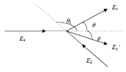
The scattering process between the CO2 laser photons and the electrons from 100 MeV LINAC is shown schematically in Fig. 1. Here and are the kinetic energies of incident and scattered electron and and are the energies of incident and scattered laser photon in the laboratory frame. (If equals , this scattering can be simplified to strict backscattering.) is the laser incident angle relative to the electron beam direction in the laboratory frame. After backscattering, the X-ray emerges in the laboratory frame at a small angle relative to the electron beam direction and the electron emerges at the angle .
The theoretical basic of Compton backscattering mechanism was described in Refs. FED80B ; SAN82 ; BLU92 . For a better understanding of this process, some important relationships will be displayed as below. One can obtain the energy of scattered photon with the help of equations for energy and momentum conservation:
| (1) |
where is the ratio of the electron and light velocities. Considering the electron energies above 50 MeV (1), and a small scattering angle (10 mrad), formula (2) can be simplified to
| (2) |
given by Federici et al. FED80B , Sandorifi et al. SAN82 and Blumberg BLU92 , where is the ratio of the total electron energy and its energy at rest: and is the electron mass at rest.
2.2 Compton scattering cross sections
The differential Compton scattering cross section for energetic electrons in the laboratory frame can be obtained starting with its form in the ER frame, in which the cross section was derived by Klein-Nishina KLE29 :
| (3) |
where , and are the classical electron radius, the ratio between the energies of scattered and incident photon, and the scattering angle in the ER frame, respectively. It can be obtained from Eq. (2) considering the electron to be at rest, i.e. . In this case, the ER and laboratory frame are equivalent. The result is:
| (4) |
Then one can obtain the Compton scattering cross section for energetic electrons in laboratory frame via Lorenz transformation:
| (5) | |||||
Energy differential cross-section of Compton backscattering X photons can be derived from formula (1) and (5):
| (6) | |||||
When injected laser beam is totally polarized, circular and linear polarization of BCS photons are presented as
| (7) |
3 The proto type of the SLEGS facility
The proto type of the SLEGS facility consists mainly of 100 MeV LINAC, CO2 laser optical system, target chamber, detector system and data acquisition system, etc. They will be introduced in detail in the following.
3.1 The 100 MeV LINAC
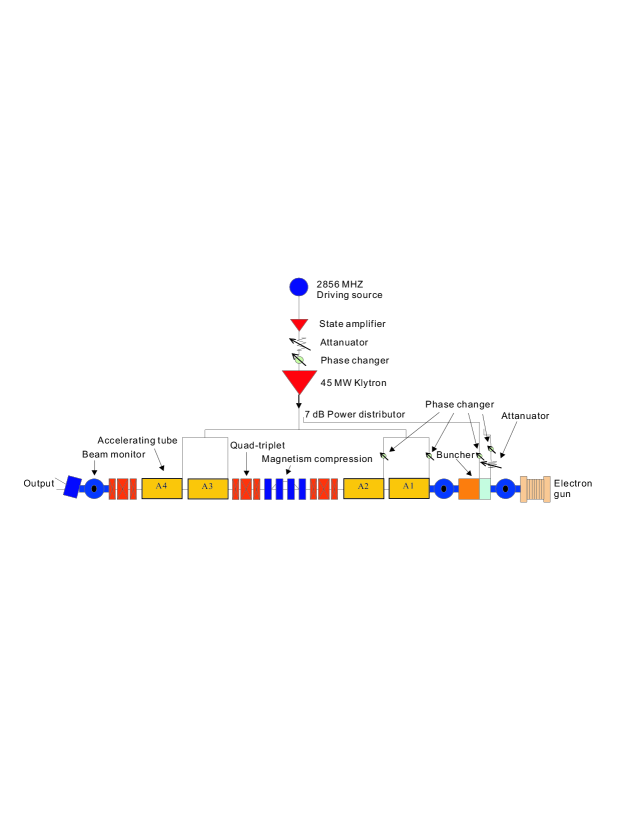
The schematic illustration for the 100 MeV LINAC is shown in Fig. 2. It is mainly composed by an electron gun, an pre-buncher and a buncher, four accelerating tubes, a focus coil, a klystron, a modulator, a microwave driving source, a phase control system, a vacuum system, a water-cooling system, a beam flux diagnosis system and a control system, etc. The total length is about 20 meters. Each accelerating tube may make the electronic energy to increase approximately 27.5 MeV. About 7 MW power from klystron is input to the buncher via the wave guide directional coupler. The klystron outputs the other microwave power to the four accelerating tubes via the wave guide merit minute, each accelerating tube power accepts about 7 MW.
3.2 Optical system
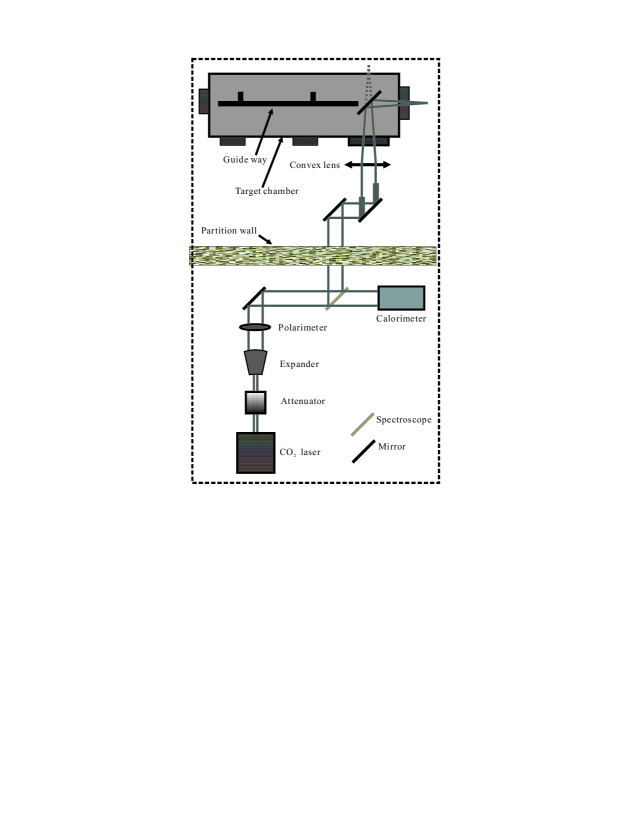
Fig. 3 display a schematic view for optical system of proto type. First, the CO2 laser will pass through an energy attenuator and then be expanded. A suitable adjustment of the positions of the two lenses will make the laser light be parallel. Then, the parallel light will be polarized linearly or circularly via the polarizing disc. Finally, the laser will be reflected and then be guided to the 100 MeV LINAC hall for the preparation of collision with electron beam. In the 100 MeV LINAC hall, the laser will be adjusted again, to make it pass vertically through target window. The details for the adjustment of laser and electron beam will be provide in following.
3.3 Target chamber
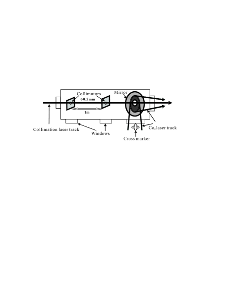
In order to reduce the loss of the CO2 laser power, the laser should transmit in a vacuum chamber. According to the present situation of 100 MeV LINAC, we plan to develop a vacuum target chamber, which is used for the entrance of laser. The schematic view for target chamber is displayed in Fig. 4. As well known, the collimation between the CO2 laser and the electron beam is very important, because it decides the energy region and the flux of X-ray. Fig. 4. displays step by step the aim between the CO2 laser and the electron beam. There are two flakes filmed fluorescence and a mirror with a hole at its center for the transmission of laser. First, one should initialize the aim via marking the track of electron beam on the two flakes. Second, another laser used for collimation will be imported and adjusted to be coaxial with the electron beam. Then the CO2 laser should be adjust to be coaxial with collimated laser. The cross marker should be used for the benchmark for the entrance of the CO2 laser. Third, to readjust the CO2 laser after the CO2 laser being fixed at the LINAC. Finally, to readjust the electron beam to make it be coaxial with the CO2 laser.
3.4 Detector system
The X-ray from Compton back scattering performed at the proto type has an energy range of 5 keV18 keV and the corresponding wave length range is about cm cm (2.50.7 Å). Therefore a HPGe detector or a Si (Li) detector is best suitable, because their survey energy scope is about 1 KeV30 KeV. The efficient area is larger than 12.5 mm2 and the energy resolution (FWHM) is smaller than 160 eV at 5.9 KeV. The related parameters for Si (Li) detector are listed in Table 1.
| Diameter | 16 mm |
|---|---|
| Efficient area | 200 mm |
| Energy resolution | 220 eV |
| Thickness of Be window | 50 m |
| Energy range | 1 30 KeV |
3.5 DAQ
Here the data acquisition refers mainly to the acquisition and processing for data from the detector terminal. So data acquisition system includes standard CAMAC and the VME data bus system, which are adopted frequently in nuclear physics as well as in high energy physics experiment.
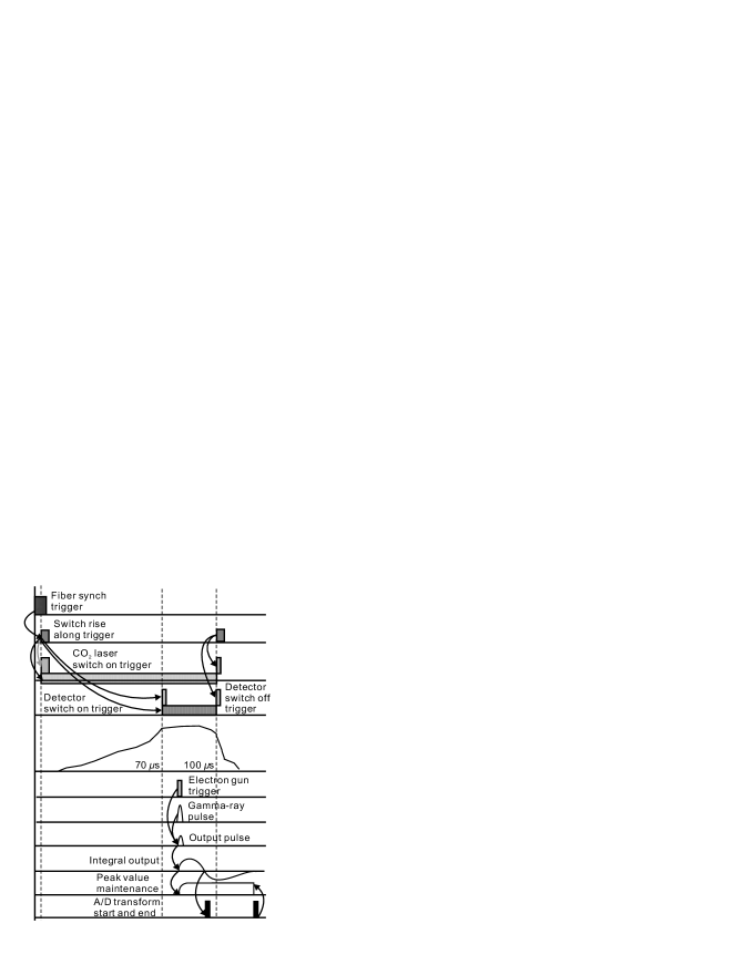
Fig. 5 displays the control illustration for DAQ. A synch trigger signal is provided by the optical fiber of the SSRF synch system. Then the light signal is transformed by the photoelectricity coupled apparatus into the switch quantity electrical signal, which is used to trigger the CO2 laser. When the laser output power approaches peak value after an exponential increase with 70 s, the CO2 laser synch system will trigger the permission logical gate of the gamma detector. The detecting time is 30 s.
When gamma rays are detected, they will be transformed into electricity pulse, which is proportional to the energy deposits of gamma rays in the detector. This pulse will be reshaped and enlarged with a maintenance of peak value. Then it passes through zero fixed time to output the A/D transformation logic pulse. After the A/D converter transforms being finished, a logic signal will be produced to end the maintenance of peak value.
4 Some simulated results and discussion
Various useful parameters for 100 MeV LINAC and for CO2 laser are listed in Table 2. All the required quantities are calculated based on the above formulas and the parameters listed in Table 2.
| 100 MeV LINAC | |
|---|---|
| Electron energy | 100 MeV |
| Pulse width | 324 ns (FHWM) |
| Normalized emittance | 107 (x)137 (y) mrad |
| Energy resolution | 0.9 |
| Mean current | 100 mA |
| CO2 laser | |
| Wave length | 10.62 m |
| Peak power | 0.251.5 kW |
| Rise/Fall time | 90 s |
| Stabilization of power | 8 |

Fig. 6a shows the relation between the energy of Compton backscattering photons and the scattered angle. The scattered angles of Compton backscattering photons above 10 keV are less than 4.6 mrad which corresponds to a beam size of 3.6 cm at the distance of 4 m from the collision point. Fig. 6b displays the differential cross section of Compton backscattering photons. It shows that the differential cross section increases sharply when the scattered angle is less than 5 mrad, which is consistent with interesting energy region above. The polarization of Compton backscattering photons is given in Fig. 6c. It can be seen that if laser light is 100% polarized, a Compton backscattered photon is highly polarized at the maximum energy. The polarization drops as the photon energy decreases as shown in Fig. 6c. However, the energy of laser photons is easily changed, so the polarization can remain be maintained reasonably high in the energy region of interest.
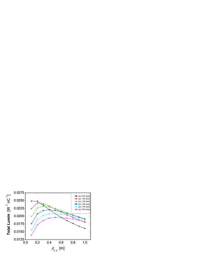
Differential luminous flux of Compton backscattering photon as a funtion of interaction length at different laser waist widths is shown in the upper part of Fig. 7. Here the electron beam is assumed to be zero emittance and its transverse widths are 200 m for direction and 100 m for direction. These two quantities will be perhaps changed a little in the real operation of the LINAC. In addition, the electron beam and the laser are assumed to be co-axis and co-focus. It is seen obviously that differential flux distributions along interaction length are different at different laser waist widths. Differential flux changes sharply with the transform of interaction position if laser waist width is very small but becomes insensitive when waist width of laser is large enough.
5 Estimation of background
The backgrounds from dipole magnet and bremsstrahlung for the proto type of SLEGS are estimated and the corresponding results are displayed in Figs. 8 and 9, respectively.


Since the radius of dipole magnet is not decided yet, three candidate radii are assumed in the calculations, which are performed using the program Xop 2.1 developed by European Synchrotron Radiation Facility (ESRF) group. The fluxes of photons from dipole magnet at three radii are much higher than that of X photons. But the energies of background are very small (less than 1 keV), which is lower than the energy of X photons of interest. So the background from dipole magnet will not cover up the X photons of interested energy region.
6 Conclusion
In conclusion, the design of proto type of SLEGS at SSRF is introduced. The related simulation results are presented and discussed. The backgrounds from dipole magnet and bremsstrahlung are estimated, respectively. From above calculations, the ideal obtained flux of X-ray is about 0.076 s-1W-1nC-1. However considering the limited reception of detector and other X-ray loss, the real flux of X-ray will be larger than 0.002 s-1W-1nC-1. If a K-500 CO2 laser is selected, its maximum power is about 1500 W. Based on the above estimation for background, the signal-noise ratio for the proto type will be larger than 30.
7 Acknowledgments
This work was supported by the Innovation Program of Science Technology of Chinese Academy of Sciences under Contract No. KJCX2-SW-N13, by the National Natural Science Foundation of China under Contract No. 10475108, and by the hundred talent project of SINAP.
References
- CAS (1975) L. Casano, et al., Laser Unconventional Optics J. 55 (1975) 3
- MAT (1977) G. Matone, et al., Lect. Notes Phys. 62 (1977) 149
- FED (1980) L. Federici, et al., Nuovo Cimento B 59 (1980) 247
- BAB (1991) D. Babusci, et al., Nucl. Instr. and Meth. A 305 (1991) 19
- DAN (2000) A. D’Angelo, et al., Nucl. Instr. and Meth. A 455 (2000) 1, and references therein.
- PAR (2001) S.H. Park, et al., Nucl. Instr. and Meth. A 475 (2001) 425
- LIT (1997) V.N. Litvinenko, et al., Phys. Rev. Lett. 78 (1997) 4569
- OHK (2006) H. Ohkuma, et al., Proceedings of EPAC 2006, Edinburgh, Scotland
- FUJ (2003) M. Fujiwara, Prog. Part. and Nucl. Phys. 50 (2003) 487
- AOK (2004) K. Aoki, et al., Nucl. Instr. and Meth. A 516 (2004) 228
- LI (2004) D. Li, et al., Nucl. Instr. and Meth. A 528 (2004) 516
- SAL (1995) E.L. Saldin, et al., Nucl. Instr. and Meth. A 362 (1995) 574
- ZHA (2004) Z.T. Zhao and H.J. Xu, Proceeding of EPAC 2004, Lucerne, Switzerland
- (14) L. Federici, G. Giordano, G. Pasquarello, and P. Picozza, Nuovo Cimento 27 (1980) 339.
- (15) A. M. Sandorfi, M. J. Levine, C. E. Thorn, G. Giordano, and G. Matone, The fabrication of a very high energy polarized gamma ray beam facility and a program of medium energy physics research at the national synchrotron light source, Brookhaven National Laboratory Report BNL-32717, BNL Physics Dept. Proposal to the Dept. of Energy (1982).
- (16) L. N. Blumberg, Kinematics of Compton backscattering X-ray source for angiography, Brookhaven National Laboratory Report BNL-47503 (1992).
- (17) O. Klein and Y. Nishina, Z. Physik 52 (1929) 853.