Determination of Deuteron Beam Polarizations at COSY
Abstract
The vector () and tensor () polarizations of a deuteron beam have been measured using elastic deuteron–carbon scattering at 75.6 MeV and deuteron–proton scattering at 270 MeV. After acceleration to 1170 MeV inside the COSY storage ring, the polarizations of the deuterons were remeasured by studying the analyzing powers of a variety of nuclear reactions. For this purpose a hydrogen cluster target was employed at the ANKE magnetic spectrometer, which is situated at an internal target position in the ring. The overall precisions obtained were about 4% for both and . Though all the measurements were consistent with the absence of depolarization during acceleration, only an upper limit of about 6% could be placed on such an effect.
pacs:
29.25.Lg, 29.27.Hj, 24.70.+s, 25.10.+sI Introduction
The COoler SYnchrotron (COSY) of the Forschungszentrum Jülich (FZJ) COSY accelerates and stores protons up to 2.88 GeV and deuterons up to 2.23 GeV both for experiments internal to the ring and for those using an extracted beam. In the case of protons, an extensive series of successful measurements with polarized beams and targets was carried out with the internal EDDA detector EDDA and, used as a polarimeter, it can determine the polarization of the beam with high precision. COSY is now embarking on a program of investigations glagolev ; STORI ; SPIN with polarized deuteron beams and polarized deuterium storage cell targets PIT at the ANKE magnetic spectrometer ANKE , placed at an internal target station of the COSY ring cosyring . Much valuable work has already been carried out to investigate the spin manipulation of the internal deuteron beams in COSY morozov . However, in order to accomplish the stated program SPIN , it is a priority to establish polarization standards for the deuteron beams, which are already available at COSY, to better than 5%. Higher precision than this has recently been achieved in ANKE for polarized proton beams yaschenko .
Due to their much smaller anomalous magnetic moment, deuterons, unlike protons, do not have to cross any first–order depolarizing resonances while being accelerated in COSY, where the typical working point tunes are through Lehrach ; morozov . Even in the case of protons, higher order resonances do not lead to any significant degradation. It is therefore expected that there should be little or no loss of polarization during acceleration and this has indeed been the experience over many years at the SATURNE synchrotron, which worked over a similar energy range Arvieux . Nevertheless, it is important to check that this is true at COSY. This has been done by measuring the beam polarization before and during the acceleration, using calibrated polarimeters, and then deriving the analyzing powers for four distinct nuclear reactions at 1170 MeV that were studied simultaneously with the ANKE spectrometer: He, elastic scattering, , and quasi–free . In all these cases consistency was found with previously published data. This confirms that we can use the Low Energy Polarimeter (LEP) to monitor accurately the beam polarization though, for its accurate determination at high energies, greater reliance would be placed upon measurements within ANKE itself. The secondary calibration standards established at 1170 MeV can, when necessary, be exported to other energies, as is routinely done for protons pollock ; yaschenko .
In Sec. II we describe the construction and operation of the polarized ion source, which is based upon the charge exchange with cesium atoms. In the configuration of the radiofrequency transitions used here, the polarized ion source provides one unpolarized plus seven other states. For each of these states there is an optimal beam vector and tensor polarization. However, these are never reached in practice and the actual values have to be established using a beam polarimeter. The deuteron beam is injected into the COSY ring at 75.6 MeV. The LEP of Sec. III, which is based upon scattering from a carbon target, is used to measure the beam polarization at this energy. Unfortunately, the LEP is only sensitive to the vector polarization of the beam, but this drawback is well made up by measurements with the EDDA polarimeter EDDA using elastic deuteron–proton scattering at 270 MeV, for which accurate analyzing powers are available sekiguchi . Consistency is found state–by–state for these two lower energy measurements, though the calibration standard is more precise for the 270 MeV data.
Only the principal elements of the ANKE spectrometer, including the Silicon Tracking Telescopes (STT) used to measure very slow particles emerging from the thin targets, are discussed in Sec. IV. The following section V describes the study of the four nuclear reactions of interest in ANKE and shows that the results obtained from the two measurements of the vector analyzing power and three of the tensor are in complete agreement with previously published results. Our conclusions are drawn in Sec. VI.
II Polarized Ion Source
II.1 Set–up of the Source
The polarized colliding beams source at COSY Gebel1 ; Gebel2 ; Gebel3 comprises three major groups of components, the pulsed atomic beam source, the cesium beam source, and the charge–exchange and extraction region. The set–up is shown schematically in Fig. 1.
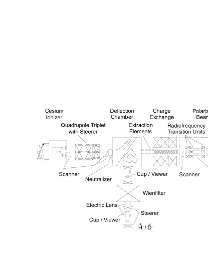
The atomic beam source produces an intense pulsed polarized atomic hydrogen or deuterium beam. The gas molecules are dissociated in an inductively coupled rf discharge and a high degree of dissociation is maintained by having a special admixture of small amounts of nitrogen and oxygen that reduces surface and volume recombination. The current output of the source depends sensitively on the relative fluxes of the gases and on their timing with respect to the dissociator radio frequency. The atoms are cooled to about 30 K by passing through an aluminum nozzle of 20 mm length and 3 mm diameter and the resulting beam is focused by an optimized set of permanent hexapoles into the charge–exchange region. By cooling the supersonic atomic beam, the acceptance of the hexapole system and the dwell time in the charge–exchange region are increased, though scattering in the vicinity of the nozzle reduces partially these beneficial effects. A peak intensity of atoms/s has been measured within a diameter of 10 mm at the exit of the hexapole chamber.
The atomic beam with high nuclear polarization collides with the fast neutral beam inside the charge–exchange region and an electron is transferred through the reaction. The ions are extracted from this region by electric fields before being deflected magnetically through , subsequently they pass a Wien filter that provides the proper spin alignment for injection into the cyclotron JULIC, which is the pre–accelerator for COSY.
The fast neutral cesium beam is produced in a two–step process. Cesium vapor is thermally ionized on a hot porous tungsten surface at a beam potential around 45 kV and the beam is then focused by a quadrupole triplet to the charge–exchange region. The space–charge compensation of the intense beam is improved by feeding mbars-1 argon to the beam tube following the extraction. Cesium sputtering and contamination generally impedes long–term reliability so that pulsed operation of the cesium ionizer has been included in the source Gebel4 . The cesium pulses reach peak intensities of over 10 mA with a width of about 10 ms. For routine operation, cesium pulses with a 5 mA flat shape of 20 ms width and a repetition rate of 0.5 Hz are used Gebel3 , matched to the COSY injection scheme. A neutralizer is placed between the quadrupoles and the cesium deflector. This consists of a cesium oven, a cell filled with cesium vapor, and a magnetically driven flapper valve between the oven and the cell. The remaining beam is deflected in front of the solenoid to the cesium cup. Routinely, a neutralizer efficiency of over 90% is achieved.
The highly selective charge–exchange ionization produces only little unpolarized background that would reduce the nuclear beam polarization. In the charge–exchange region, various beam properties can be adjusted. Transverse emittance can be traded for polarization by varying the solenoid’s magnetic field. The field strength during normal operation is 1.8 kG. The magnitude of the electrical drift field inside the solenoid can be tuned to optimize the energy spread of the beam. The electric field gradient amounts to 0.5–1.0 V. A monotonic gradient, in combination with a double buncher system in the injection beam line to the cyclotron, leads to an improved bunching factor of about four, compared to a factor of two for unpolarized beams.
Without modification of the system, the colliding–beams ion source can provide negatively–charged polarized hydrogen and deuterium beams of comparable intensities. To prepare polarized deuterons with the desired combinations of vector and tensor polarization, the atomic beam part of the source is equipped with new radiofrequency transitions (RFTs). These transition units are operated at the magnetic fields and radiofrequencies that allow exchange of occupation numbers of the different hyperfine states in deuterium haeberli . A set of three installed devices, RFT1 to RFT3, allows a large number of combinations to be delivered to experiments, as described in the following section.
II.2 Operation of the Source
The polarized or ion beam delivered by the source, is pre–accelerated in the cyclotron JULIC and injected by charge exchange into the COSY ring. The acceleration of vertically polarized protons and deuterons at COSY is discussed in detail for example in Ref. Lehrach .
The scheme used to produce the polarized deuteron beam consists of eight different states, including one unpolarized state and seven combinations of vector and tensor polarizations, obtained by switching on or off the three radiofrequency transitions RFTi, where . The states and the nominal (ideal) values of the polarizations ( and ) and relative intensities () are listed in Table 1. The polarized ion source was switched to a different polarization state for each injection into COSY, in order to reduce the systematic errors. The duration of a COSY cycle was sufficiently long ( s) to ensure stable conditions for the injection of the next state rf-switch . After the seventh state, the source was reset to the zeroth mode and the pattern repeated for the next injection. The ANKE data acquisition system received status bits from the source, latched during injection. This ensured the correct identification of the polarization states during the experiment.
III Beam Polarimetry
III.1 Low Energy Polarimeter
To assist in the optimization of the polarization of the beams inside COSY, a Low Energy Polarimeter (LEP, located in the injection beam line) consisting of a UHV chamber with eight flanges covered with thin stainless steel foils has been used cracow . The moveable target frame is equipped with viewers, allowing adjustment of the beam position. Several carbon targets can be used for polarimetry measurements based on C elastic scattering. It is possible to place detectors at azimuthal angles , , and in the ranges of polar angles to and to . NaI scintillators, directly coupled to photomultipliers, are used for particle identification. A set of exchangeable apertures, placed in front of the scintillators, defines the acceptance of the detector to be for the measurements discussed here.
The LEP is used at the COSY injection energy of MeV ( MeV/c). Studies of the cross section, analyzing power , and the resulting figure of merit for 70 MeV Kato and 76 MeV Stephenson deuterons suggest that the polarimeter should work best if the detectors are placed to accept polar angles near . Unfortunately, under such conditions the tensor analyzing powers are very small for this reaction so that the LEP is only sensitive to the vector polarization of the beam improvement . Taking the two data sets Kato ; Stephenson together, we deduce that at 75.6 MeV.
| Mode | RFT1 | RFT2 | RFT3 | |||||||
|---|---|---|---|---|---|---|---|---|---|---|
| 0 | 0 | 1 | Off | Off | Off | — | ||||
| – | 0 | 1 | Off | Off | On | |||||
| + | +1 | 1 | Off | On | Off | |||||
| – | –1 | 1 | Off | On | On | |||||
| + | – | On | On | Off | ||||||
| –1 | +1 | On | On | On | ||||||
| +1 | +1 | On | Off | Off | ||||||
| – | – | On | Off | On |
After pulse height analysis of the detector signals, the recorded spectra were fitted with a Gaussian plus a small residual linear background. The LEP set–up is operated with appropriate intensity to ensure that the dead–time of the data acquisition system (DAQ) is negligible. With the stable spin axis of the beam oriented along the –direction, the number of particles scattered through a polar angle and an azimuthal angle , after corrections for beam luminosity, can be written as Ohlsen
| (1) |
The beam vector and tensor polarizations, and , are labeled conventionally in the reference frame of the source, whereas the vector and tensor analyzing powers, , , and , refer to the reaction frame, where and lie respectively within and perpendicular to the plane of the COSY ring.
Confining to the case of right () and left () counters placed at and , respectively, this reduces to:
| (2) |
Using the measured values of Kato , together with an expected tensor polarization of the deuteron beam of , it is seen that the contribution of a tensor polarized beam to the number of scattered particles is on the percent level so that, to the desired level of accuracy, we can take
| (3) |
The results of the measurements with the LEP for the different states are shown in Table 1. Also given are the ratios of to the ideal polarization that could be provided by the source for that state. The variation from 66% to 82% depends, among other things, on the number of RFTs involved, as indicated in the table.
III.2 EDDA Polarimeter
The EDDA detector has been used to provide a wealth of high quality polarized proton–proton elastic scattering data over a wide range of energies (0.5–2.5 GeV) by using a thin internal target and measuring during the energy ramp of the COSY accelerator EDDA . With the same apparatus, elastic scattering of polarized deuterons from hydrogen was studied at MeV ( MeV/c) EPAC , where precise values are known for both tensor and vector analyzing powers sekiguchi . In this way values of both vector and tensor polarizations of the circulating deuteron beam could be obtained at this energy.
A fit to the data with the polarizations for all eight states being left as free parameters yields for state–0. Any non–zero result might reflect a residual polarization of state–0 or could be due to an instrumental asymmetry, e.g. caused by detector efficiencies. The data cannot distinguish between these two possibilities. Therefore, the EDDA values for the polarizations of the seven states shown in Table I, were extracted under the assumption that state–0 is unpolarized. Although supported by direct measurements with the LEP, the uncertainty of about has to be considered as a systematic uncertainty on all the polarizations extracted using EDDA.
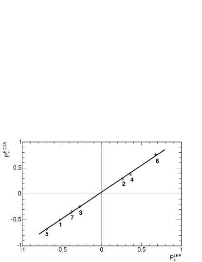
Since the EDDA and LEP data sets were taken with the same conditions in the source, in order to determine the systematic uncertainty of the polarizations, we compare quantitatively the two sets of results for . This is done for the seven states in Fig. 2 using the data of Table 1. A linear fit of the two sets of results with gives . The value of the offset constant is compatible with the precision of the EDDA calibration, as shown by the error bar in the polarization of state–0. The total systematic error of the slope in Fig. 2 amounts to , where the accuracy of the analysing powers and the EDDA polarization determination has been taken into account. Within these uncertainties, the observed slope is consistent with unity. The typical fractions of the ideal vector and tensor polarizations were 74% and 59% respectively, though values from the individual polarization states were used in the subsequent analysis of the ANKE results.
IV Experimental Set–up
IV.1 ANKE Magnetic Spectrometer
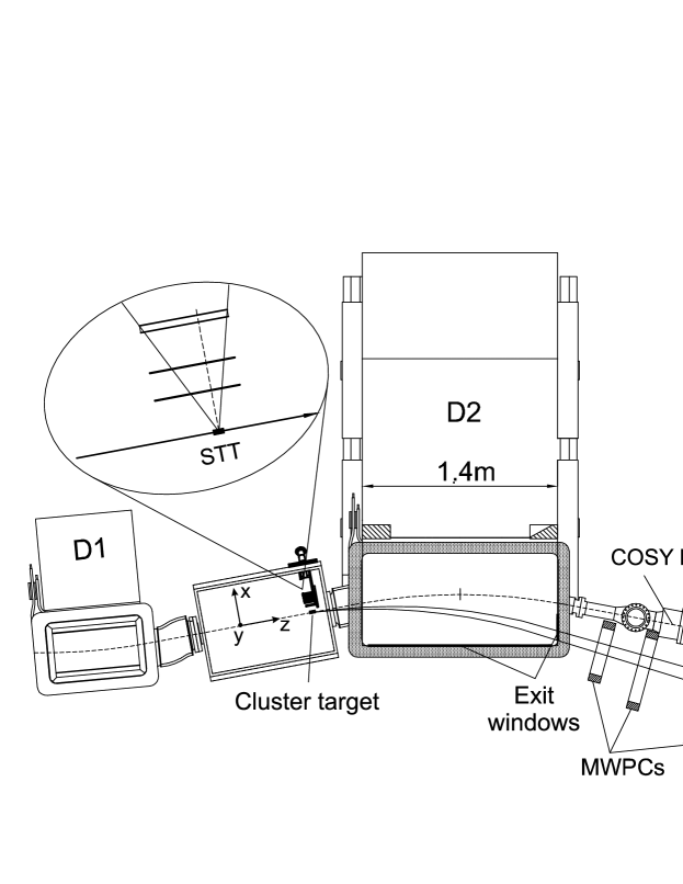
After being accelerated in the COSY ring COSY , the values of the deuteron beam polarizations provided by EDDA and LEP can be checked by measuring various nuclear reactions at MeV ( MeV/c) using the ANKE spectrometer. This apparatus is described in Ref. ANKE and we shall merely discuss the details of its additional features. Thus Fig. 3 shows only those parts of the spectrometer that are relevant for the present experiment. The hydrogen cluster–jet target of areal density atoms/cm2 khoukaz , combined with an internal beam of about stored vertically polarized deuterons, provides a luminosity of up to cm-2s-1.
The reactions that are pertinent to this polarization study are:
-
,
-
Quasi–free with a fast spectator proton,
-
producing a fast pair of protons with low excitation energy, and
-
at small angles.
The first three reactions can be measured using foremost information from the ANKE Forward Detector (FD) system chil ; dymov . This comprises a set of three multi–wire proportional chambers (MWPCs) and a three–plane scintillation hodoscope, consisting of vertically oriented counters (8 in the first plane, 9 in the second, and 6 in the third). The third layer was implemented mainly to identify 3He. The hodoscope system is capable of detecting also pairs of particles, such as the protons emerging from the deuteron charge–exchange reaction komarov . Though deuteron–proton elastic scattering can also be identified largely by using the FD information, coincidence measurements with the slow recoil proton being detected in a Silicon Tracking Telescope (STT) yields more precise information.
IV.2 Silicon Tracking Telescope
For the identification and tracking of slow recoil protons, a Silicon Tracking Telescope (STT) has been developed schleichert that can be operated inside the ultra–high vacuum of the accelerator. The basic detection concept of the STT combines proton identification with tracking over a wide range in energy. The tracking is accomplished by three layers of double–sided micro–structured silicon strip detectors that can be placed close to the target inside the vacuum chamber (see Fig. 3). The set–up of the STT is shown in Fig. 4.
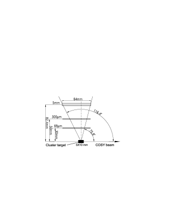
Measuring the energy loss in the individual layers allows identification of stopped particles by the method. A proton is registered when it passes through the inner layer and is stopped in the second layer, so that the minimum energy of a proton that can be tracked is determined by the thickness of the innermost layer. The maximum energy of tracked protons is given by the range within the telescope and hence by the total thickness of all detection layers. Therefore, the primary design goal in the development of the STT was to combine the thinnest possible innermost with the thickest available outermost layer of silicon detector.
A first generation STT inti was already equipped with three detection layers: a non–structured 60 m thick layer, a single–sided structured 300 m, and a 5100 m thick detector. Although serving mainly as a prototype system with limited size and poor tracking capabilities, it allowed us to study the reactions inti , barsov , and it was also used as a polarimeter yaschenko .
The new STT employs the well–established thickness of the first generation system, but overcomes the limited tracking capabilities by using double–sided micro–structured detectors. The angular coverage in the forward hemisphere was small, because the position of the STT with respect to the target was optimized to detect slow recoil protons in the backward hemisphere. Nevertheless, protons emitted at angles from about to were unambiguously identified in the STT in coincidence with elastically scattered deuterons in the FD.
The new STT facilitates proton identification from 2.5 up to 40 MeV with an energy resolution of 150–250 keV (FWHM). Particle tracking is possible over a wide range of energies with an angular resolution varying from 1∘ to 6∘ (FWHM). The resolution is limited by angular straggling within the detectors and therefore depends on particle type, energy, and track inclination. The geometrical limit is defined by the strip pitch (ranging from 400 to 666 m) and the distances between the detectors. The STT has self–triggering capabilities. It identifies a particle passage within 100 ns and provides the possibility for fast timing coincidences with other detector components of the ANKE spectrometer, whereby accidental coincidences can be suppressed significantly. The high rate capabilities of the STT will be especially important for the upcoming polarization experiments SPIN , because then two or more STTs have to be placed in the forward hemisphere. The recent development of very thick ( mm) double–sided micro–structured Si(Li) detectors will allow us to extend further the accessible energy range of the STT protic .
V Measurements with ANKE
V.1 Identification of Nuclear Reactions
Figure 5 shows the ANKE experimental acceptance for charged particles as function of the laboratory production angle and magnetic rigidity. From the loci of the kinematics of the four reactions that we investigated in this polarization study it was seen that all of them had reasonable acceptances over some angular domain.
The main trigger used in the experiment consisted of a coincidence of different layers in the hodoscope of the FD. The 3He were identified by means of a special energy loss trigger in the FD. In parallel, self–triggering of the STT was employed to identify unambiguously elastic scattering.
Candidate events for different reaction channels can be identified in a plot of the time of flight difference between target and hodoscope () vs the calculated time of flight difference (), assuming the two forward particles hitting different hodoscope counters are protons, as shown in Fig. 6. Real proton pairs from the charge–exchange breakup are located along the diagonal of the scatter plot, where for illustration, it also shows how events from other reactions are transformed by this procedure.
V.2 Extraction of the Analyzing Powers
After classifying the events shown in Figs. 5 and 6 in terms of various nuclear reactions, these were binned in intervals of center–of–mass polar angle (), or equivalently the three–momentum transfer (), and azimuthal angle (). The resulting counts or were corrected for the dead–time of the DAQ system, which was typically 10–15%, and which was measured with a precision of better than 1%.
In order to establish the relative integrated luminosity of each of the polarization states involved, we normalized the data using the beam current information. The signal from the beam current transformer (BCT) was fed into a voltage–to–frequency converter within the EDDA electronics and transformed into an optical signal to avoid deterioration. This information was transported to ANKE where, after conversion back to a NIM–signal, it was fed into the ANKE scaler system. In this way the BCT signal was available in the normal ANKE data stream for each of the polarization states. The BCT signal is known to about 1%.
After further correction of the measured counts for luminosity, with the help of the above beam current information, the various analyzing powers of the reactions were extracted by fitting Eq. (1) simultaneously to the data obtained for all the source states, which have different values of the beam polarizations and . The details of such a fit in the case are discussed extensively in Ref. Chil1 .
Reliable values of can only be extracted provided that the apparatus has useful –acceptance away from or , but there are significant differences in this for the four reactions presented below.
V.3 He Reaction
It is seen from Fig. 5 that there is a large acceptance for the reaction when the 3He are emitted very close to the initial beam direction. In this region there are very detailed measurements of the sole non–vanishing deuteron (tensor) analyzing power as a function of energy Kerboul . The high–momentum branch of particles could be selected in off–line analysis by applying two–dimensional cuts in vs momentum and vs momentum for individual layers of the forward hodoscope. The was identified through the missing mass derived from the measurement, as described in Ref. wronska . The mean value of the missing mass distribution (Fig. 7) was close to the pion mass, with stable background of less than 3%. Though the resulting peak has a large width, this is not critical since, apart from the radiative capture, there should be no physical background in this region, and no significant amount is seen in the figure.
Using the counts within a missing–mass range of the peak in Fig. 7, we find an analyzing power of , where the statistical and systematical uncertainties in the EDDA beam polarizations given in Table 1 have not been included. Interpolation of the SATURNE data to our energy leads to a value of Kerboul .
V.4 Quasi–Free Scattering
In the bulk of reactions involving collisions with a deuteron at intermediate energies the process is driven by the interaction with either the proton or neutron in the nucleus. The other particle is a spectator, a fact that has led to the extensive use of deuterium as a replacement for a free neutron target. In the case of a deuteron beam, a spectator proton () would have roughly half the momentum of the beam and be detectable over a range of angles, as shown in Fig. 5.
The first step in extracting quasi–free events from our data is to choose two–track events on the basis of the MWPC information. The momentum vectors were determined with the help of the magnetic field map of the spectrometer, assuming a point–like source placed in the center of the beam–target interaction region. The smallness of the FD solid angle acceptance leads to a kinematic correlation for events with two or three particles in the final state. The candidates can be clearly identified from the correlation of the measured time difference and the calculated time of flight difference (see Fig. 6). The reaction shows up as isolated regions in a two–dimensional plot without having to identify positively the deuterons beforehand. For both the high deuteron momentum part (forward production in the cm system), and the low momentum region (backward production) the missing masses corresponding to the unobserved are clearly seen in Fig. 8.
For small deuteron cm angles the spectrometer provides useful –acceptance over the full angular range. However, for events in the backward hemisphere, this is restricted rather to , which is quite sufficient to extract the vector analyzing power .
Provided that the spectator momentum in the deuteron rest frame is small, the vector polarization of the deuteron is completely given by that of the constituent nucleons. The shape of the spectator momentum distribution follows the expectation for a reasonable deuteron wave function paris . By selecting events below 60 MeV/c, dilution of the neutron polarization due to –state effects in the deuteron becomes negligible.
Due to isospin invariance, the neutron analyzing power in the reaction should be identical to that of the proton in , for which extensive data compilations are available SAID . As shown in Fig. 9, the agreement of our result with the SAID data base is very good for both small and large deuteron cm angles. (Numerical values can be found in Table 2.) This result is therefore consistent with the EDDA measurements of the vector polarization of the deuteron beam. Within small error bars, typically 2%, there is no sign of any effect arising from the tensor polarization of the deuteron beam. This is as expected for a quasi–free reaction and provides an extra check on the systematics.
V.5 Charge–Exchange Reaction
The deuteron charge exchange on hydrogen, is defined to be the reaction when the di–proton emerges with low excitation energy . It has been argued that for small momentum transfers from the deuteron to the di–proton, the counting rates should depend sensitively upon the tensor polarization of the beam and that the relatively large analyzing powers could be estimated reliably in terms of neutron–proton elastic amplitudes Bugg-Wilkin . These impulse approximation predictions were successfully tested at 1.6 GeV using the SPES-IV spectrometer at SATURNE Sams95a . Similar measurements at 200 MeV and 350 MeV with the EMRIC device Kox were equally well described by the model, which was subsequently extended to include final–state interactions in several of the partial waves Carbonell . The reaction also provides the basis for the design of the POLDER polarimeter POLDER , which has been used for the determination of the polarization of the recoil deuteron in elastic electron–deuteron scattering at JLab JLab . In addition to a large analyzing power, the signal for the reaction of two fast protons emerging both with momenta close to half of the beam, is very distinctive and in our case these fall within the acceptance of the FD system (Fig. 5).
The detection of proton pairs was already successfully exploited during earlier measurements komarov ; yaschenko . The charge–exchange breakup events can be isolated from the scatter plot in Fig. 6 in exactly the same way that the reaction was studied. The identification of the charge–exchange process was finally confirmed from the missing mass with respect to the observed proton pairs (see Fig. 10) and the time–difference information. The spectra for all spin modes reveal a well defined peak at M equal to the neutron mass within 1%. The background was less than and stable.
As shown in Ref. Chil1 , there is sufficiently large acceptance for all azimuthal angles when events with MeV are selected. Large values are obtained for both and , whereas is consistent with zero to better than 1%, as expected from theory Bugg-Wilkin . The results are presented in Fig. 11 as a function of the momentum transfer from the proton to the neutron. They are compared to the predictions of the impulse approximation, using the same computer program as that in Ref. Carbonell , though with modern values of the amplitudes taken from the SAID phase shift analysis SAID ; Igor1 . Since, for small , this reaction only depends upon the tensor polarization of the beam Bugg-Wilkin , the agreement shown in Fig. 11 is an excellent confirmation of the EDDA values of that we have used.
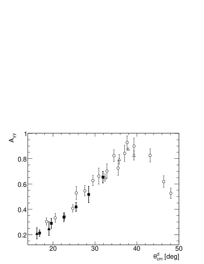
V.6 Deuteron–Proton Elastic Scattering
It is obvious from Fig. 5 that deuteron–proton elastic scattering has a significant acceptance in ANKE for . Because of the very large cross section, the reaction stands out very clearly in the momentum and angle–momentum spectra, and is thus easily selected. The elastic peak region in the momentum spectrum of the single track events, shown in the left panel of Fig. 12, was fit by a Gaussian. Values within of the mean momentum were considered to be good elastic scattering events. An example of such a fit is shown in the right panel of the figure.
In contrast to the three reactions measured in ANKE that we have discussed thus far, elastic scattering depends upon both the vector and tensor polarizations of the deuteron beam. Fortunately the analyzing powers , , and of this reaction have been measured at Argonne Argonne for MeV and SATURNE Arvieux for MeV.
There is good azimuthal coverage of this reaction in ANKE for . This is quite sufficient to extract the values of the vector analyzing power shown in Fig. 13 (left panel). Comparing with the Argonne and SATURNE results, the agreement is very good, with all points coinciding within the published statistical errors.
The situation is not quite as clean in the case of the tensor analyzing power since the small –acceptance does not allow us to obtain . Nevertheless, the finite acceptance does lead to a small contamination of the measurement from the term. We therefore introduced a correction of about 4% to account for this effect using information derived from the ratio determined at Argonne Argonne , where it should be noted that this ratio does not depend on the beam polarization used in their analysis. The agreement presented in Fig. 13 (right panel) is very satisfactory; Numerical values of and are given in Table 2.

Though the events identified from the FD information shown in Fig. 12 are very clean, some of the systematics of the experiment can be checked from the data where the slow recoil proton from the elastic scattering was detected in the silicon telescope in coincidence with the deuteron in the FD. Though this restricts both the acceptance and the statistics, the determination of the angles and the total lack of any background presents in principle many advantages. However, as shown in the figure, the results hardly change when this coincidence is introduced.
V.7 Precision of the ANKE Results
The numerical results from the measurements described in this section are given in Table 2 of Appendix A. We here discuss separately the precisions with which each of the reactions determines one of the beam polarizations with the aim of extracting the best values and errors for and at MeV. This will also allow us to put limits on the amount of depolarization by the beam through acceleration to this energy.
Though the reaction in the forward direction has a very strong tensor analyzing power signal, the statistical error achieved so far at ANKE does not allow us to make a strong statement on the basis of these results. Comparing with the precise results from SATURNE Kerboul , we find that
| (4) |
The reaction is only sensitive to the vector polarization of the beam. We find that the analyzing power at different angles is proportional to the SAID prediction for SAID with
| (5) |
where . Although the SAID database does not allow one to extract errors, the numerous experiments in this range suggest an overall precision of about 3% Furget . Allowing also for a possible small violation of charge independence that links the and analyzing powers, a very conservative estimate on the error in from this reaction is about 5%.
The statistical precision that can be achieved for the tensor analyzing powers in the reaction is very high. Assuming the validity of the impulse approximation predictions Carbonell illustrated in Fig. 11, we obtain
| (6) |
Since there are some uncertainties in the theoretical model as well as in the input, a more cautious limit on the tensor polarization of the beam would be 5%. However, it should be noted that some of the uncertainty might cancel if the reaction were used to extract information about the amplitudes at other energies.
Elastic deuteron–proton scattering is sensitive to the vector and tensor polarizations of the beam. Comparing our measurements of for with those of Argonne Argonne shown in Fig. 13a, the average over the points near the maximum yields
| (7) |
Unlike the case for the vector analyzing power of , there are clear discrepancies between the measurements of Argonne Argonne and SATURNE Arvieux for the tensor analyzing power shown in Fig. 13b, with the latter being lower. This was remarked upon in the SATURNE paper and great care was then taken to establish very accurate values of the beam polarizations. Using the SATURNE and renormalized Argonne values, we find for this reaction that
| (8) |
However, for neither of the two analyzing powers have we tried to include corrections for the small differences in beam energy between the different experiments.
Putting all these results together, we see that
| (9) |
The error bars on the “Expected” results are obtained from theory and a variety of experiments around MeV. However, they do not explicitly include the uncertainties of and in the SATURNE values of and . If one takes these into account then the uncertainties in the vector and tensor polarizations of the deuteron beam in ANKE are both on the 4% level.
The central values shown in Eq. (9) reflect the possible loss of polarization during the acceleration of the deuterons from the EDDA energy to that of ANKE. Though these indicate very little depolarization, one cannot draw very tight limits on this effect because of the uncertainties introduced by the calibration of the EDDA polarimeter. Taking just the systematic errors of 4% here, we suggest that any polarization loss is below 6% for both the vector and tensor parameters.
VI Conclusion and Outlook
By measuring five analyzing powers in ANKE, we have shown that it is possible to determine both the vector and tensor polarizations of the deuteron beam at 1170 MeV with precisions of about 4% each. The vector and tensor polarizations are typically about 74% and 59%, respectively, of the ideal values that could be provided by the source. Taking these results in conjunction with the values of the polarizations measured with the EDDA polarimeter, we find no evidence for any depolarization in the acceleration from EDDA to ANKE. However, we can only put limits of about 6% on such effects because of the extra uncertainty in the absolute calibration of EDDA. A somewhat stronger limit might be found if we assumed that any degradation of were associated with one of , though this argument should be taken with some caution morozov . One way to eliminate calibration effects completely would be by decelerating the beam and remeasuring in EDDA itself.
Since ANKE can accept many nuclear reactions simultaneously there are, of course, other processes that might be used to check the beam polarizations. One of these is proton–deuteron backward elastic scattering, for which tensor analyzing powers are available A-B . However, the cross section is rather low and our measurement of the analyzing power has a 15% statistical error, which make the reaction of very limited use for the present purposes. One might think of using quasi–elastic proton–proton scattering to determine , with one particle being detected in ANKE and the other in the STT. Though we have high statistics measurements of this reaction, it is not appropriate to use this to calibrate the vector polarization. In the small momentum transfer region allowed by the ANKE acceptance, there are large corrections to the quasi–free picture coming from final–state interactions Chil1 , so that one cannot use free scattering to determine the polarization. Nevertheless the reaction might be useful to provide on–line monitoring of .
The results achieved here allow us to extend our measurements to higher energy, where they can be used to add to the existing scattering data base. It is known that in the forward direction provides similar information to that of the spin–transfer parameter in neutron–proton elastic scattering in the backward direction Bugg-Wilkin . At 788 MeV this parameter has been measured with a systematic precision of better than 3% but the statistical error bars were at the 8–15% level McNaughton . Nevertheless, these data represent a significant contribution to the amplitude analysis at this energy. Hence, the measurements of and in the reaction with systematic errors below 5% should provide useful data at this and especially at higher energies, where the existing information is poorer.
The deuteron charge exchange is just one part of the polarization
schedule at the COSY–ANKE facility SPIN . Polarized
hydrogen and deuterium targets are currently being commissioned,
and the combination of polarized beams and targets will lead
to a very rich physics program.
Acknowledgements.
We would like to thank the accelerator crew for the operation of COSY, the injector cyclotron, and the polarized ion source. We are grateful to I.I. Strakovsky for providing us with up–to–date neutron–proton amplitudes, and to E.J. Stephenson for valuable information regarding deuteron analyzing powers at low energies. We thank D. Protić and Th. Krings (FZJ) for providing the Si(Li) detectors.Appendix A Tabulated Results
In Table 2, we give the numerical results of the measurements of analyzing powers and of elastic scattering (Sec. V.6), analyzing power of the quasi–free reaction (Sec. V.4), and the value of the analyzing power of the He reaction from ANKE (Sec. V.3), together with the previously obtained SATURNE result Kerboul .
| FD | |||
| FD+STT | |||
| He | |||
| ANKE | |||
| SATURNE |
References
- (1) R. Maier, Nucl. Instr. Meth. A 390, 1 (1997).
- (2) M. Altmeier et al., Eur. Phys. J. A 23, 354 (2005), and references therein.
- (3) V. Glagolev (for the ANKE Collaboration), Proc. XVII Int. Baldin Seminar on High Energy Physics Problems, Relativistic Nuclear Physics and Quantum Chromodynamics, eds. A.N. Sissakian, V.V. Burov, A.I. Malakhov, Dubna, Russia, 2004, JINR, p. 192 (2005)
- (4) A. Kacharava et al., Proc. 6th Int. Conf. on Nuclear Physics at Storage Rings, eds. D. Chiladze, A. Kacharava, and H. Ströher, Bonn, Germany, 2005, Schriften des Forschungszentrums Jülich, 30, 104 (2005).
- (5) A. Kacharava, F. Rathmann, and C. Wilkin for the ANKE Collaboration, COSY Proposal #152, Spin Physics from COSY to FAIR, arXiv:nucl-ex:0511028.
- (6) F. Rathmann et al., Proc. 15th Int. Spin Physics Symp., eds. Y.I. Makdisi, A.U. Lucio, and W.W. MacKay, Upton, New York, 2002, AIP Conf. Proc. 675, 924 (2003).
- (7) S. Barsov et al., Nucl. Instr. Meth. A 462, 364 (2001).
- (8) A floorplan of the COSY accelerator complex can be found in Fig. 1 of ref. morozov .
- (9) V.S. Morozov et al., Phys. Rev. ST Accel. Beams 8, 061001 (2005).
- (10) S. Yaschenko et al., Phys. Rev. Lett. 94, 072304 (2005).
- (11) A. Lehrach et al., p. 153 of ref. PIT .
- (12) J. Arvieux et al., Nucl. Instr. Meth. A 273, 48 (1988).
- (13) R.E. Pollock et al., Phys. Rev. E 55, 7606 (1997).
- (14) K. Sekiguchi et al., Phys. Rev. C 65, 034003 (2002).
- (15) P.D. Eversheim et al., Proc. Int. Symp. High Energy Spin Physics, eds. C.W. De Jager, J.E. Oberski, and P.J. Mulders, Amsterdam, The Netherlands, 1996, p. 306 (World Scientific, Singapore, 1997).
- (16) R. Weidmann et al., Rev. Sci. Instr. 67, 1357 (1996).
- (17) O. Felden et al., Proc. Int. Workshop on Polarized Sources and Targets, Nashville, 2001, eds. V.P. Derenchuk and B. von Przewoski, Nashville, USA, 2001, (World Scientific, Singapore, 2002) p. 200.
- (18) M. Eggert et al., Nucl. Instr. Meth. A 453, 514 (2000).
- (19) W. Haeberli, Ann. Rev. Nucl. Sci. 17, 373 (1967).
- (20) The time it takes for the atomic beam polarization to stabilize after a change of state is very short compared to the cycle time. When only the rf is switched in an RFT, the atomic beam polarization becomes stable within 0.02 s, and within 0.5 s, if in addition the magnetic field is changed.
- (21) P.D. Eversheim, Proc. of the Workshop on Polarized Ion Sources and Polarized Gas Targets, eds. L.W. Anderson and W. Haeberli, Madison, Wisconsin, USA, 1993, AIP Conf. Proc. 293, 92 (1993). M. Eggert, PhD thesis, University of Cologne (1999).
- (22) S. Kato et al., Nucl. Instr. Meth. A 238, 453 (1985).
- (23) E.J. Stephenson, Deuteron Polarimeter for Electric Dipole Moment Search, Proc. XIth Int. Workshop on Polarized Sources and Targets, Tokyo (2005) (in press), available from http://www.iucf.indiana.edu/~dedm/conferences/pst05.ppt, and private communication.
- (24) In order to improve the polarimetry directly at the COSY ion source, a new polarimeter for proton and deuteron beams, based on the concept of the ANKE Lamb–shift polarimeter engels , is presently being installed.
- (25) G.G. Ohlsen, Rep. Prog. Phys. 35, 717 (1972).
- (26) B. Lorentz et al., Proc. European Particle Accelerator Conference, Lucerne, Switzerland, 2004, ISBN 92-9083-231-2, p.1246 (2005).
- (27) A. Khoukaz et al., Eur. Phys. J. D 5, 275 (1999).
- (28) B. Chiladze et al., Part. Nucl., Lett. 4, 95 (2002).
- (29) S. Dymov et al., Part. Nucl. Lett. 2, 40 (2004).
- (30) V. Komarov et al., Phys. Lett. B 553, 179 (2003).
- (31) R. Schleichert et al., IEEE Trans. Nucl. Sci. 50, 301 (2003).
- (32) I. Lehmann et al., Nucl. Instr. Meth. A 530, 275 (2004).
- (33) S. Barsov et al., Eur. Phys. J. A 21, 521 (2004).
- (34) D. Protić et al., accepted for publication in IEEE Trans. Nucl. Sci. (2005).
- (35) D. Chiladze et al., submitted for publication (nucl-ex/0601038 v2).
- (36) C. Kerboul et al., Phys. Lett. B 181, 28 (1986). C. Kerboul, PhD thesis, University of Strasbourg (1987); A. Boudard (private communication).
- (37) A. Wrońska et al., Eur. Phys. J. A 26, 421 (2005).
- (38) M. Lacombe et al., Phys. Lett. B 101, 139 (1981).
- (39) R.A. Arndt, W.J. Briscoe, R.L. Workman, and I.I. Strakovsky, http://gwdac.phys.gwu.edu/analysis/nn_analysis.html
- (40) D.V. Bugg and C. Wilkin, Nucl. Phys. A 467, 575 (1987).
- (41) T. Sams et al., Phys. Rev. C 51, 1945 (1995).
- (42) S. Kox et al., Nucl. Phys. A 556, 621 (1993).
- (43) J. Carbonell, M.B. Barbaro and C. Wilkin, Nucl. Phys. A 529, 653, (1991).
- (44) S. Kox et al., Nucl. Instr. Meth. A 346, 527 (1994).
- (45) D. Abbott et al., Phys. Rev. Lett. 84, 5053 (2000).
- (46) I.I. Strakovsky (private communication).
- (47) M. Haji-Said et al., Phys. Rev. C 36, 2010 (1987).
- (48) see e.g. C. Furget et al., Nucl. Phys. A 655, 495 (1999).
- (49) J. Arvieux et al., Phys. Rev. Lett. 50, 19 (1983).
- (50) R. Engels et al., Rev. Sci. Instrum. 74, 4607 (2003); R. Engels et al., Rev. Sci. Instrum. 76, 053305 (2005).
- (51) M.W. McNaughton et al., Phys. Rev. 48, 256 (1993).