The Laser Calibration System of the ALICE Time Projection Chamber
Abstract
A Large Ion Collider Experiment (ALICE) is the only experiment at the Large Hadron Collider (LHC) dedicated to the study of heavy ion collisions. The Time Projection Chamber (TPC) is the main tracking detector covering the pseudo rapidity range . It is designed for a maximum multiplicity dN/dy= 8000. The aim of the laser system is to simulate ionizing tracks at predifined positions throughout the drift volume in order to monitor the TPC response to a known source. In particular, the alignment of the read-out chambers will be performed, and variations of the drift velocity due to drift field imperfections can be measured and used as calibration data in the physics data analysis. In this paper we present the design of the pulsed UV laser and optical system, together with the control and monitoring systems.
pacs:
25.75.-q, 25.75.Nq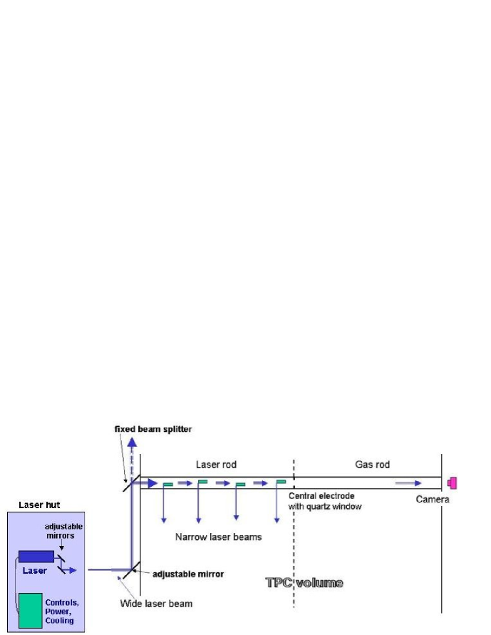
The ALICE experiment will study heavy ion collisions at LHC. The main tracking detector of the ALICE experiment is the TPC[1]. The aim of the laser system is to generate straight tracks at known positions in the drift volume of the TPC. These tracks will be generated by two-photon ionization of the drift gas by a pulsed UV laser beam with a wave length of 266 nm. Other electrons are emitted by photoelectric effect when the laser beam hits metallic surfaces such as the central electrode, the aluminized mylar strips of the electric field cage, or wires and pads of the readout system. After readout and track reconstruction using the TPC detector, distorsions related to ExB effects and mechanical misalignment will be measured and corrected using these tracks. The spatial and temporal variations of the drift velocity due to the drift field will be measured within a relative error of and used as calibration data in the physics analysis.

The calibration system is composed of a static optical system and of adjustable parts. The static optics is composed of beam splitters, mirrors and bending prisms guiding the laser beam around the TPC field cage before it enters the TPC volume. The guiding system ends with cameras that are able to take pictures of the laser beam in order to monitor the position and the beam intensity. The adjustable part is mainly composed of remotely adjustable mirrors that will guide the beam into the static optics system. In order to generate multiple tracks in the TPC, the laser beam goes through several steps. First, a 25 mm diameter laser beam is divided into 6 secondary beams by splitters before entering the TPC from one side (Fig. 2). Each beam enters the TPC in a rod (Fig. 1), passes through the central electrode and, for monitoring purposes, is detected by a camera located on the other side of the TPC. In each rod, there are 4 fixed micro-mirror bundles. Each of them extracts seven 1 mm-diameter beams (20-40 J/pulse) from the secondary beam and reflects them as rays into the drift volume. A second laser beam generates similar rays in the second half of the TPC. Thus 336 laser beams on the whole (Fig. 2) will be created inside the TPC volume [2].
The actual laser is from Spectron Laser Systems Ltd, model SL805-UPG. The RS232 laser connections are converted into a TCP/IP connection with an interface from Digi International[3] company in order to be able to control the laser over long distances. The laser is controled by a C++ serial port driver included in a DIM[4] server under Windows XP. This server communicates with a DIM client included in the user interface. The laser delivers 5 ns pulses at a repetition rate of 10Hz. The energy of a pulse is 100 mJ for a wave length of 266 nm at the entrance of the end cap. A second laser will be installed in the laser hut, at z m. Both lasers can be used in parallel, one for each end cap, or one for both end caps, the other one being kept as a backup [2, 5].
Two adjustable mirrors are used to align the laser beam in the guiding system on the TPC endplates. They are controlled by New Focus hardware and software for TCP/IP connections.
Cameras (up to 16) will monitor the laser beams. At each end cap one camera is placed behind the movable mirror. Two others can be placed at the end of the two bends. Moreover, 12 extra cameras are at the end of each rod. All these cameras will take pictures of the laser beam in order to monitor its intensity and its position.
A synchronization board will synchronize laser pulses and cameras with the LHC clock. This board was developed for the Detector Control System of the TPC and TRD detector in ALICE[1, 6].
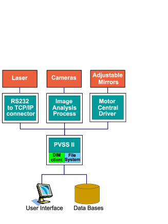
The Calibration Laser Control System (Fig. 3) is set up to provide an easy and safe structure to use the laser from the control room. It will be integrated into the Detector Control System of ALICE. Images of the laser spot recorded by cameras can be processed in order to move mirrors to align laser beams inside rods. All sub-systems (the laser, cameras and adjustable mirrors) will be controlled by a common Supervisory Control And Data Acquisition called PVSS (Prozessvisualisierungs-und Steuerungs-System) inside the Join Controls Project framework[7], giving a trustable user interface.
As a conclusion, all optical elements will be set up and aligned in the TPC from november 2005 to february 2006. This includes micro-mirror bundles in rods, mirrors and prisms in support wheels, adjustable mirrors and cameras. The laser will be operational in spring 2006, ready for generating multiple tracks for TPC tests with cosmic rays in summer 2006.
References
- [1] ALICE Collaboration:ALICE Technical Design Report of the Time Projection Chamber, CERN/LHCC 2000-001 (2000).
- [2] B.S. Nielsen, J. Westergaard, J.J. Gaardhøje, A. Lebedev and ALICE TPC Collaboration: Design Note on the ALICE TPC laser calibration system, ALICE-INT-2002-022 (2002).
- [3] http://www.digi.com/
- [4] http://dim.web.cern.ch/dim/
- [5] D. Beck: DCS User Requirement an Architectural Design Specifications for the Calibration Laser Sub-System for the ALICE TPC.
- [6] ALICE Collaboration:ALICE Technical Design Report of the Transition Radiation Detector, CERN/LHCC 2001-021 (2001).
- [7] http://itcobe.web.cern.ch/itcobe/Services/Pvss/