Optical calibration hardware for the Sudbury Neutrino Observatory
Abstract
The optical properties of the Sudbury Neutrino Observatory (SNO) heavy water Cherenkov neutrino detector are measured in situ using a light diffusing sphere (“laserball”). This diffuser is connected to a pulsed nitrogen/dye laser via specially developed underwater optical fibre umbilical cables. The umbilical cables are designed to have a small bending radius, and can be easily adapted for a variety of calibration sources in SNO. The laserball is remotely manipulated to many positions in the D2O and H2O volumes, where data at six different wavelengths are acquired. These data are analysed to determine the absorption and scattering of light in the heavy water and light water, and the angular dependence of the response of the detector’s photomultiplier tubes. This paper gives details of the physical properties, construction, and optical characteristics of the laserball and its associated hardware.
keywords:
Sudbury Neutrino Observatory , water Cherenkov detector , pulsed optical source , light diffusing sphere , laserball , underwater umbilical cable , detector calibration , photomultiplier angular response , timing calibration of large PMT arrayPACS:
06.60.Sx , 07.60.Vg , 29.40.Ka , 42.72.Bj , 78.20.Ci , 95.55.Vj, , , , , , , ††thanks: Present address: Laboratório de Instrumentação e Física Experimental de Partículas (LIP), Av. Elias Garcia, 14, 1∘, 1000-149 Lisboa, Portugal.
1 Introduction
The Sudbury Neutrino Observatory (SNO) detector is designed to detect Cherenkov light produced by solar neutrino interactions in heavy water (D2O). The accuracy of the solar neutrino measurements depends on a detailed knowledge of the detector operating conditions, of which the optical properties play a dominant role.
The SNO detector distinguishes itself from other large-volume water Cherenkov detectors in its use of 1 kt of D2O contained in a 12 m diameter acrylic vessel (AV) [1]. The AV is suspended in H2O which provides shielding from natural radioactivity in the detector components and the surrounding rock cavity. To provide shielding from cosmic rays, the detector is located 2 km underground in the INCO Creighton mine near Sudbury, Canada. Light emitted in the detector is captured by 9456 photomultiplier tubes (PMTs) arranged on a 17 m diameter geodesic support structure (PSUP). The determination of light attenuation in the heavy and light water and the PMT response as a function of incident angle are part of the optical calibration (OCA) [2, 3, 4, 5]. The determination of the relative timing offsets of the PMT electronic channels are part of the PMT calibration (PCA). These calibrations determine crucial parameters for the precise reconstruction of the energy, position and direction of neutrino candidate events used in the analyses of solar neutrinos [6, 7, 8, 9, 10, 11], as well as for the searches for nucleon decay via ’invisible’ modes [12], electron antineutrinos [13], supernova neutrinos [14] and analyses of atmospheric neutrinos and muons [15].
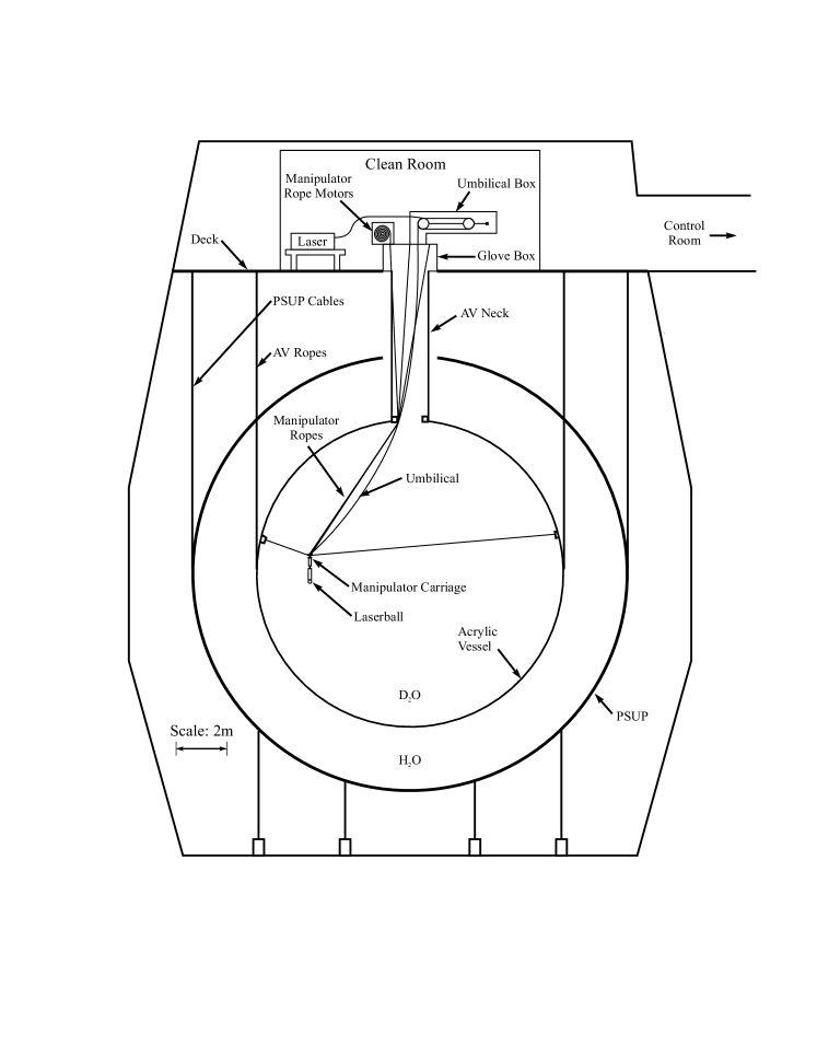
The optical calibration hardware described in this paper consists of a light diffusing sphere (“laserball”), an underwater optical fibre umbilical cable and a pulsed dye-laser light source. These components are shown in Figure 1, along with the source manipulator system that is used to manoeuvre different calibration sources, including the laserball, inside the AV. An overview of the SNO detector design, including a description of the manipulator system, is given in Ref. [1]. The overall system requirements are briefly described in the next section. The following three sections contain a detailed description of the design and construction of each of the optical calibration subsystems, followed by a brief summary of the laserball performance in SNO.
2 System requirements
The OCA hardware must provide good coverage of the detectable Cherenkov spectrum, which extends from 300 to 700 nm. The pulse intensity must be adjustable for single photoelectron level, at of PMTs triggered per laser pulse, equivalent to a ratio of multi- to single-photon hits of , in order to maximize the timing measurement precision.
While the OCA uses data taken at many laserball positions, the PCA is done with the laserball only at the centre of the detector and at 505 nm only. The choice of this wavelength for the PCA is done for several reasons:
-
•
minimum effects from scattering (Rayleigh scattering coefficient is about cm-1 at 505 nm);
-
•
reduced time-delayed fluorescence in the optical fibres (low level below 400 nm, reaching at 337 nm [3], below detection above 400 nm);
-
•
high PMT quantum efficiency (85% of the peak value, which is at 440 nm);
-
•
good transmission in all the materials: acrylic ( above 370 nm), H2O ( between 280 and 540 nm) and D2O ( above 340 nm).
Good timing of the detected photons is required by both the OCA and the PCA to allow the discrimination between light coming directly from the source and late light which has been scattered or reflected from other detector elements [2]. Since the PMT hit times are used in the event reconstruction, the PCA requires the optical pulse timing width – determined essentially by the laser pulse width and by the dispersion in the fibres and the laserball – to be small relative to the intrinsic 1.5 ns resolution of the PMTs [1].
3 Laserball
The laserball was designed and built to calibrate the optical characteristics of the SNO detector by emitting a quasi-isotropic light distribution in the far-field (i.e., at distances large compared to the laserball’s dimensions) [4, 3, 2, 5]. The final design of the laserball, described in this paper and shown schematically in Figure 2, was achieved after a series of iterations.
The laserball consists of a 10.9 cm diameter quartz flask filled with 0.5 kg of silicone gel [16], in which 2 g of 50 m diameter air-filled hollow glass spheres [17] are suspended. In the assembly of the laserball, uniform distribution of the scattering spheres is achieved by continuous agitation of the flask during the 15 minutes cure time of the silicone gel. It was verified that bubbles formed in the gel (so it had to be refilled) if the laserball was brought to the surface from the underground SNO laboratory.
The mounting hardware is made of stainless steel except for the acrylic window (for inspection of the fibre loop during assembly). The quartz flask has a straight neck with a restraining ring, and is completely filled with silicone gel.

The polished tip of the fibre bundle coming from the umbilical cable (see Section 4) is coupled to a single rigid fibre, the bottom tip of which is placed slightly above the centre of the laserball such that the light emitted by the fibres is redirected by refraction and total internal reflection at the glass-air interface inside the hollow glass spheres. This results in a smoothly varying, quasi-isotropic far-field intensity distribution. This distribution is only weakly dependent on the wavelength even for low concentrations of scatterers. The mean free path of light between the hollow glass spheres is cm, which is a compromise between guaranteeing far-field uniformity and reducing time dispersion and light absorption. Monte Carlo simulations of the laserball [4] indicate that the light appears to come from a diffuse region with an effective diameter of 4 cm.
The far-field light distribution of the laserball can be adjusted by moving the fibre tip: a displacement of 1 mm results in a change of approximately 10% in the intensity pattern at 385 nm. Only a coarse adjustment is required, since the PCA depends only on the timing, and for the OCA the laserball light distribution is fit along with the optical parameters using an optical model of the detector [2] (as it will be described in Section 6).
In addition to the small residual anisotropy in the light distribution of the laserball due to the placement of the optical fibres, there is a larger asymmetry due to shadowing by the mounting hardware. The light within approximately 60∘ of the vertical is progressively shadowed, reaching a reduction of directly above the laserball. To minimize reflections from the mounting hardware and to prevent the detection of light emitted from the neck of the flask, a cylindrical polished stainless steel light shield extends to just above the ball surface.
4 Umbilical cables
The multi-purpose underwater “umbilical” cables were designed to be flexible and robust for use with the source manipulator system, and to provide services for the operation of all the SNO calibration sources [2]. The optical fibre umbilical contains a bundle of optical fibres for transmitting light from the laser down to the laserball. This section describes the requirements, design and fabrication process of the umbilical cables.

4.1 Requirements and design
Design requirements for the umbilicals included:
-
•
Radioactivity cleanliness: suitable for deployment in SNO for periods of up to several weeks at a time without introducing a significant 222Rn contamination (emanation lower than 10 mBq, which correspond to 10% of the level in the D2O);
-
•
Impermeability to water to protect cable components and the source itself;
-
•
High flexibility with a small bending radius, for use with the manipulator;
-
•
Length of 30 m, to reach the farthest available positions inside SNO;
-
•
Neutral buoyancy in D2O with constant linear density over its length.
Cables with these specifications were not available commercially, so the expertise to construct them was developed within the SNO Collaboration. A short length of umbilical cable is shown in Figure 3, with its cross-sectional view depicted in Figure 4.
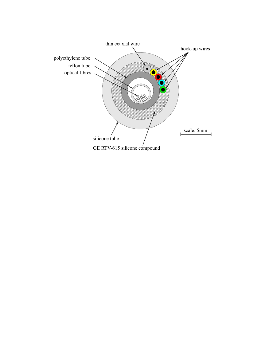
An umbilical consists of a 30.5 m long silicone tube with an outer diameter (OD) of 12.7 mm containing a smaller 6.35 mm OD polyethylene tube [18] helically wrapped with four thin Teflon-insulated hook-up wires and a thin coaxial cable [19]. The four wires and the coaxial cable centre the polyethylene tube inside the umbilical, and the helical wrapping permits longitudinal tensile and compressive forces on the wires to be relieved locally as the umbilical goes over the pulleys of the manipulator system. Both of these effects are important in reducing the minimum bending radius for use with the manipulator system with its 15.2 cm and 20.3 cm diameter pulleys. Additionally, the central polyethylene tube provides mechanical support to the fibres, both radially (against crushing) as well as longitudinally (against stretching).
For the laserball umbilical, 20 optical fibres [20] were used to allow for redundancy in the case of breakage, and to simplify the injection of light from the laser while preserving adequate light intensity at the laserball. The high-OH (hydroxyl) core fibres provide low attenuation and low time dispersion over the wavelength range 337–619 nm probed in the optical calibration.
The optical fibres are put in a small Teflon tube [18], which protects them during assembly and deployment. The fibres are deliberately kept loose inside the Teflon tube so that they do not take any load and can move relative to the umbilical. Having the fibres on the neutral bending axis of the umbilical also greatly reduces mechanical stresses during deployment.
Variations on the basic umbilical design include replacing the fibre bundle with a gas capillary for two short-lived radioactive gas sources (16N [21] and 8Li [22]), replacing the 6.35 mm polyethylene tube with a high-voltage cable [19] for a small proton-tritium accelerator source [23], or a fast coaxial cable [24] for a thoriated anode proportional counter source [1]. Thus one basic umbilical design has been adapted to provide services to all the SNO calibration sources.
4.2 Umbilical Fabrication
The umbilicals are made by first wrapping the four small hook-up wires and the thin coaxial wire around the polyethylene tube, and this assembly is then drawn into the silicone tube. The volume between the silicone tube and the polyethylene tube is filled with a clear, transparent, two-component liquid silicone [16] which forms a robust, impermeable layer between the silicone tube and the inner components. The filling of the umbilicals with silicone is a critical step in their manufacturing. At room temperature, the highly viscous ( Pas) RTV615 silicone remains fluid for four to six hours after its components are mixed. During this time, the viscosity increases steadily until the fluid stops flowing freely. Therefore, a high-pressure injection system was developed to force the RTV615 into the umbilical within the first hour after mixing.
To hold the silicone tubing in place, it is inserted into eight 3.65 m and one 1.3 m sections (total length: 30.5 m) of thin-walled 15.875 mm OD copper piping. The inner diameter of the copper piping is only slightly larger than the OD of the silicone tube. The silicone tube is wrapped back around the ends of the copper pipe to form a seal and is “inflated” by evacuating the volume between the copper pipes and the outside of the silicone tubing. This anchors the silicone tube to the copper pipe by friction and allows the helically-wrapped polyethylene tube to be drawn through the silicone tube without stretching the latter.
The umbilical in its copper pipe housing is connected at one end to an injection piston and at the other to an evacuated drum, which eliminates trapped air between cables or at the front edge of the flow of liquid silicone. At the injection end of the umbilical, a special “T”-fitting is used to ensure the silicone is forced into the annular region between the polyethylene and the silicone tubes. The injection piston was designed to fulfill two goals: degassing the silicone immediately after mixing at partial vacuum pressure ( kPa), and then injecting the silicone into the umbilical at relatively high pressure ( MPa). Because of the limited time available for the umbilical filling, the degassing step was kept short ( minutes). In consequence, a long horizontal acrylic piston (183 cm 7.62 cm OD, wall thickness 6.35 mm) was used, exposing a large surface area of fluid to the vacuum and permitting visual monitoring during the degassing and injection steps.
Under the injection pressure, the umbilical is expanded against the constraining copper pipes by the silicone. The remaining time until the silicone stops flowing freely allows this pressure to be relieved (the silicone is permitted to escape from both ends). The finished umbilical can be easily removed from the copper pipes once the RTV615 is fully cured two days later.
5 Laser system
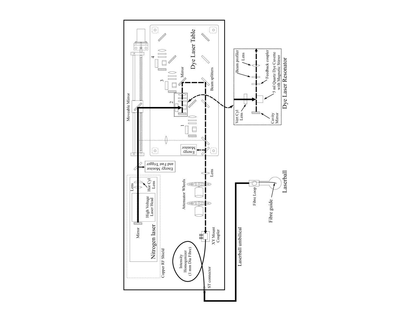
The laser system consists of a short pulse-length nitrogen laser ( nm) which can be made to pump a series of up to five laser dyes at longer wavelengths ( = 369, 385, 420, 505 and 619 nm). Figure 5 shows the layout of the laser system, consisting of the following components:
-
1.
Commercial N2 TEA (Transversely Excited Atmosphere) thyratron triggered ultraviolet pump laser (Class IIIb [25]).
The laser head is a channel 10 cm long with a 4 mm electrode gap and a feedback mirror at one end of a high voltage (15 kV) parallel plate capacitor. The output is super-radiant and therefore lacks the coherence of a cavity mode laser. The laser is enclosed in a copper radio-frequency (RF) shield, which attenuates the high levels of RF radiation emitted during the rapid high voltage discharge across the gas cell. This is critical because the RF noise is synchronous with the laser light.
-
2.
Optical table where four dye laser resonator units and associated beam optics are mounted. The dye laser cell is selected by moving a mirror mounted on a computer controlled lead screw carriage. The fifth dye cell is swapped manually.
The nitrogen laser beam is focused through a cylindrical lens to a line just inside the dye cell cuvette wall. The cavity mirror and feedback coupler generate a well defined beam along the focused edge of the cuvette (mounted at an angle so that feedback from internal reflections are not amplified). The resulting beam is approximately 2 mm in diameter with a half-angle divergence of 3 mrad and rectangular diffraction fringes. The cuvette holders incorporate a motor that magnetically drives a stirring agitator in the bottom of the cuvette.
The beam optics are set so that the beams from the four dye laser units converge on a single axis using four semi-reflective mirrors. By putting the longest wavelength in the fourth dye cell and the shortest in the first, these steering mirrors partially compensate for the higher attenuation of shorter wavelengths in the optical fibres.
-
3.
Two computer controlled attenuator wheels with 8 positions each: open, beam stop, 6 coarse adjustment neutral density (ND) filters in the first wheel, and 6 finely spaced ND filters in the second wheel. The combined neutral density is adjusted to produce pulses with an intensity equivalent on average to single photoelectron illumination of all the tubes (as mentioned before, this allows about 5% of all the PMTs to be illuminated by each pulse).
-
4.
An intensity homogenizer (1 mm diameter fibre, 1 m long) to remove pulse-to-pulse beam pattern instabilities.
-
5.
Remote and local system power control and trigger control of pump laser and trigger lockout.
-
6.
Pump beam and dye beam laser energy monitors, amplifiers, and a fast beam activated event trigger. The latter is generated by a fast reverse biased MRD500 PIN diode, that produces a negative pulse of 0.8 ns full width. This provides superior timing compared to command triggering of the laser, which would include about 5 ns timing jitter due to the logic circuits and the thyratron switch.
-
7.
Heavy aluminum box consisting of a cm base plate, an angle frame and 1.5 mm thick sheet aluminum covers on all sides. This box provides mechanical stability for the optical components and prevents dust from getting in, and RF or laser radiation from getting out.
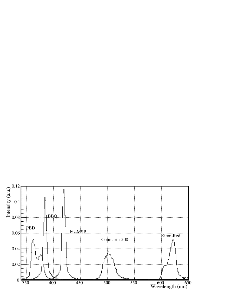
The dye wavelengths used are listed with other key parameters of the laser system in Table 1. Figure 6 shows the stimulated emission spectra of each of the dyes. The spectra were measured by using the dyes in a commercial N2/dye laser unit [26] coupled to a spectrophotometer that has a 2 nm resolution. The measured peak positions and widths are compatible with the manufacturer’s nominal values. Differences in peak wavelength of about 1% or lower are observed when comparing the spectra of dyes used for 3 years in SNO with those of newly mixed dyes. Such differences can cause a negligible systematic effect of about 0.1% in the refractive index, so the impact of dye degradation in the analysis of SNO data is not significant.
Table 2 shows the relevant contributions to timing dispersion in the laser system coupled through optical fibres (total length 45 m) to the laserball. The fibre dispersion measurements [3] were made by using a setup in which the fibre is looped over a large drum and a small PMT detects photons that scatter out of the fibre for each pass of a light pulse produced by a fast N2 pulser lamp. The PMT timing spectrum contains multiple peaks offset by the loop transit time and the width of those gives the dispersion as a function of the distance.
| Pulse width | ns |
|---|---|
| to 0.5 ns | |
| Pulse Energy | E J/pulse or photons |
| E to 30 J/pulse | |
| Pulse Rate | 1 to 45 Hz |
| 337.1 nm | N2 laser fundamental, nm |
| 369 nm | PBD, nm |
| 385 nm | BBQ, nm |
| 420 nm | Bis-MSB, nm |
| 505 nm | Coumarin 500, nm |
| 619 nm | Kiton Red, nm |
| Wavelength | Laser width | Fibre optic | Laserball | Net width |
|---|---|---|---|---|
| dispersion | dispersion | |||
| 337.1 nm | 0.6 ns | 0.5 ns | 0.3 ns | 0.8 ns |
| 369 nm | 0.3 – 0.5 ns | 0.5 ns | 0.3 ns | 0.7 – 0.8 ns |
All the source manipulation operations can be done remotely, except for the actual source insertion (and removal) within the AV. A fifth resonator unit was recently added to the optical table, so all wavelengths can be selected with no manual intervention. Therefore, with the exception of the occasional replacement of the laser N2 supply, the optical calibration system can be operated remotely, which makes it easier to conduct around-the-clock, multiple-day calibrations since access to the SNO underground laboratory is limited.
6 Performance of the optical source
The laserball (LB) distribution is implemented in the OCA model as a combination of a a 2-dimensional matrix of the polar angle cosine versus the azimuthal angle and a sixth-order polynomial function on only. The polynomial function allows the model to accomodate a rapidly varying distribution without increasing the size of the matrix.
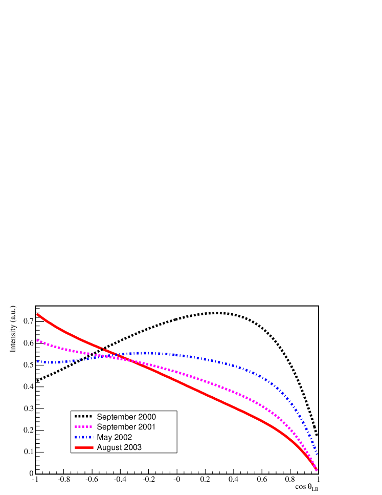
Figure 7 shows the far-field laserball intensity distribution, determined by the OCA for four different calibration scans at 505 nm, as a function of the polar angle cosine. A strong variation of the polar light distribution is expected at close to 1 due to shadowing by the source support hardware. Away from the top region, the polar variation of the light intensity can be up to % and is likely determined at assembly by the exact configuration of gaps between the fibre bundle and the rigid fibre (since this can influence the angular distribution of light arriving to the gel). The laserball used in the September 2000 scan is different from the one used in the later scans. The variations between the September 2001, May 2002 and August 2003 are likely due to variations in the laserball-umbilical coupling and degradation of the gel.
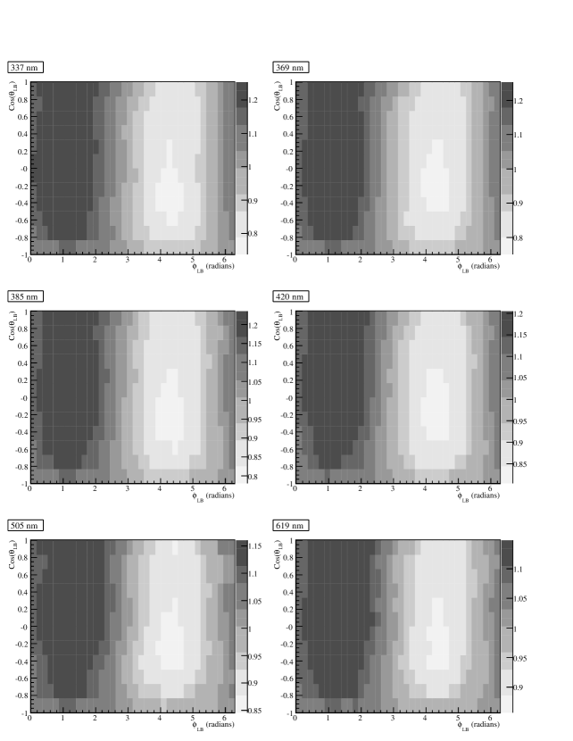
Figure 8 shows the laserball intensity distribution determined by the OCA for each wavelength [2], after taking into account the polar angle dependence shown in Figure 7. The grey scale indicates the relative light intensity as a function of the cosine of the polar angle, , and azimuthal angle, . The light intensity varies by % at 619 nm, increasing to % at 337.1 nm The azimuthal light distribution is dominated by a dipole distribution, caused by misalignment of the fibre tip inside the laserball. The larger asymmetry at shorter wavelengths is likely the effect of increased absorption in the laserball gel and glass spheres.
The OCA must determine average optical properties of the whole detector. So it is important for the variation in azimuthal distribution to be smooth and relatively small, as shown in Figure 8, to guarantee a good sampling of all the PMTs. Fluctuations in the laserball intensity that occur in a short timescale (less than a week) can affect the accuracy of the OCA during a multi-day scan. Hence, runs are repeated at specific positions throughout the scan to ensure the stability of the light intensity.
7 Conclusions
An accurate calibration of the optical properties of SNO is a vital step in understanding the performance of the detector. Measurements with the laserball system at six wavelengths from 337.1 nm to 619 nm allow the optical properties to be sampled over the detectable Cherenkov light spectrum. These optical data for the OCA are taken approximately twice per year, each time for one week around the clock. The system is fully remotely controlled so that continuous underground access to the SNO laboratory is not necessary.
The short pulse length and good uniformity characteristics of the light distribution permit the simultaneous relative timing and collected charge calibrations(PCA) of all 9456 PMT channels to be accomplished efficiently. The timing calibration is performed at 505 nm because the light intensity varies by only 15%, and absorption and scattering are low in all three media (D2O, H2O and acrylic). These calibrations are done monthly.
The laserball system has proven very robust over more than 2500 hours of operation. Limited maintenance has been required, such as new charge transfer boards for the laser head and realignment of the mirrors. The umbilical cables, made using a novel manufacturing technique, are flexible, clean, robust and versatile: the basic umbilical design was easily modified to provide gas, electrical connections or simply act as a support line for each of the eight other SNO calibration devices.
The optical calibration hardware enables the detector optics to be probed in situ and provides the essential timing reference for all PMT channels. These calibrations are crucial to the energy and position reconstruction of events, and are essential to the precision of SNO’s solar neutrino data analysis.
Acknowledgements
This research was supported in part by the Natural Sciences and Engineering Research Council of Canada, and the Fonds pour les Chercheurs et l’Aide à la Recherche of the province of Québec, Canada.
References
- SNO Collaboration [2000] SNO Collaboration, Nucl. Instr. and Meth. A449, 172 (2000).
- Moffat [2001] B.A. Moffat, The Optical Calibration of the Sudbury Neutrino Observatory. PhD thesis, Queen’s University, Kingston, Ontario, Canada, July 2001.
- Ford [1998] R.J Ford, Calibration of SNO for the Detection of 8B Neutrinos. PhD thesis, Queen’s University, Kingston, Ontario, Canada, December 1998.
- Ford [1993] R.J. Ford, Nitrogen/Dye Laser System for the Optical Calibration of SNO. Master’s thesis, Queen’s University, Kingston, Ontario, Canada, October 1993.
- Grant [2004] D.R. Grant, Optical Calibration of the Sudbury Neutrino Observatory and Determination of the 8B Solar Neutrino Flux in the Salt Phase. PhD thesis, Carleton University, Ottawa, Ontario, Canada, March 2004.
- SNO Collaboration [2001a] SNO Collaboration, Phys. Rev. Lett. 87, 071301 (2001)a.
- SNO Collaboration [2001b] SNO Collaboration, Phys. Rev. Lett. 89, 011301 (2002)b.
- SNO Collaboration [2001c] SNO Collaboration, Phys. Rev. Lett. 89, 011302 (2002)c.
- SNO Collaboration [2004c] SNO Collaboration, Phys. Rev. Lett. 92, 181301 (2004)c.
- SNO Collaboration [2005c] SNO Collaboration, nucl-ex/0502021, submitted to Phys. Rev. Cc.
- SNO Collaboration [2005c] SNO Collaboration, hep-ex/0507079, submitted to Phys. Rev. Dc.
- SNO Collaboration [2004c] SNO Collaboration, Phys. Rev. Lett. 92, 102004 (2004)c.
- SNO Collaboration [2004c] SNO Collaboration, Phys. Rev. D70, 093014 (2004)c.
- Heise [2001] J. Heise, A Search for Supernova Neutrinos with the Sudbury Neutrino Observatory. PhD thesis, University of British Columbia, December 2001.
- Tagg [2001] N. Tagg, The 8Li Calibration Source and Through-going Muon Analysis in the Sudbury Neutrino Observatory. PhD thesis, University of Guelph, January 2001.
- [16] GE Silicones, Silicone gel RTV6196 for the laserball, Silicone rubber RTV615 for the umbilicals.
- [17] 3M Company, 3M Scotchlite Glass Bubbles.
- [18] McMaster-Carr, Silicone rubber tubing: translucent, medium hard (50 Shore A Durometer), 9.53 mm ID, 12.7 mm OD. Low-density polyethylene tubing: black, 4.32 mm ID, 6.35 mm OD. TFE Spaghetti tubing: 11 AWG TW, 3.30 mm OD, 0.30 mm wall thickness.
- [19] Belden Inc., Hook-up wires: Belden 83003, 24 AWG (American Wire Gauge) stranded 1936, 1.12 mm OD. Thin coaxial cable: Belden 83265, 50, 1.27 mm OD with outer insulation removed (1.80 mm nominal OD with white FEP (Fluorinated Ethylene Propylene) outer insulation. High-voltage cable: Belden 8866, 18 AWG stranded 1630, 5.28 mm OD, 40 kV suggested working voltage.
- [20] Fiberguide Industries, Superguide G high-OH fibres with a core/cladding/jacket geometry of 100/140/250 m, part number SFS 100/140Y.
- Dragowsky et al. [2002] M.R. Dragowsky et al., Nucl. Instr. and Meth. A481, 284 (2002).
- Tagg et al. [2002] N. Tagg et al., Nucl. Instr. and Meth. A489, 178 (2002).
- Poon et al. [2000] A.W.P. Poon, R.J. Komar, C.E. Waltham, M.C. Browne, R.G.H. Robertson, N.P. Kherani, and H.B. Mak, Nucl. Instr. and Meth. A452, 115 (2000).
- [24] Times Microwave Systems, Times Microwave Systems LMR-200, 4.95 mm OD, 50.
- [25] Laser Photonics Inc., LN203C nitrogen TEA laser.
- [26] Photon Technology International, GL-3300 laser; GL-302 dye module.