Two–photon exchange and elastic scattering
of electrons/positrons on the proton.
(Proposal for the experiment at VEPP-3.)
J. Arringtona, V.F. Dmitrievb,
R.J. Holta, D.M. Nikolenkob,
I.A. Rachekb, Yu.V.Shestakovb, V.N. Stibunovc, D.K. Toporkovb,
H.de Vriesd.
a ANL, Argonne, IL 60439-4843, USA,
b BINP, 630090 Novosibirsk, Russia,
c NPI at TPU, 634050 Tomsk, Russia,
d NIKHEF, P.O. Box 41882, 1009 DB Amsterdam, The Netherlands
1 Introduction.
The study of the electromagnetic form factors of the proton – important properties of this fundamental object – allows increased understanding of the nature of the proton, as well as the nature of interactions of its constituents - the quarks. Until recently, the electric () and magnetic () form factors, which describe the distribution of charge and current inside the proton, were determined by the separation of longitudinal and transversal contributions to the electron–proton scattering cross section. Differential cross section of the elastic scattering in one–photon approximation, assuming and invariance, can be written [1] as:
where is the Mott cross section, is electron scattering angle, is transfered four-momentum, and . Introducing the longitudinal virtual photon polarization, , one can re-write the above formula as:
The two form factors can be disentangled by measuring scattering cross sections at different initial electron energies and scattering angles while keeping momentum transfer () the same. Such a procedure is called Rosenbluth separation or Rosenbluth technique. As is seen from the last formula, the contribution of the electric form factor to the cross section drops down with increasing . Therefore it becomes difficult to measure using the Rosenbluth method at high .
In the mid-nineties, it became possible to use polarization transfer experiments to study nucleon electromagnetic form factors. Through such measurements contributions of interference terms into the scattering cross-section become accessible, hence the contribution of the small form factors can be enhanced resulting in increased accuracy of their determination. A series of precise measurements of the ratio of proton form factors for a wide range of transfered momentum was carried out recently at TJNAF [2]. In these experiments a ratio of transverse () and longitudinal () polarization of recoil protons from elastic scattering of longitudinally polarized electrons on an unpolarized hydrogen target was measured. In such a case the ratio of proton form factors can be extracted directly from the ratio of and :
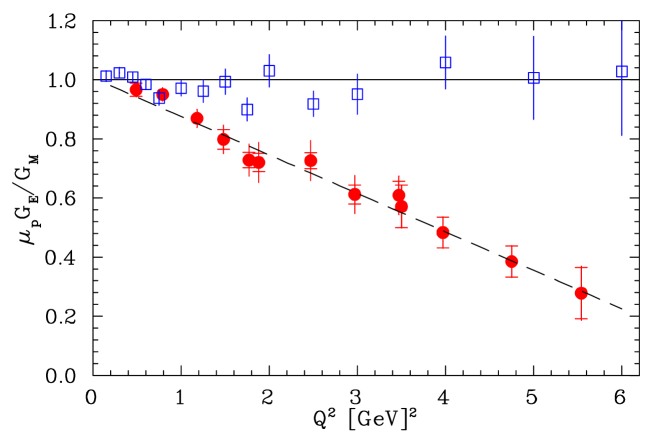
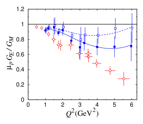
where are the electron energy before and after scattering and is the proton mass. These polarization experiments yielded unexpected results, indicating that the ratio depends strongly on , while before it had been assumed to be nearly constant, close to unity (see Fig. 1).
A thorough reanalysis of the available unpolarized experimental data [3], as well as new precise unpolarized measurements done at TJNAF [4] have clearly shown that these two methods deliver contradictory results.
2 Two–photon exchange.
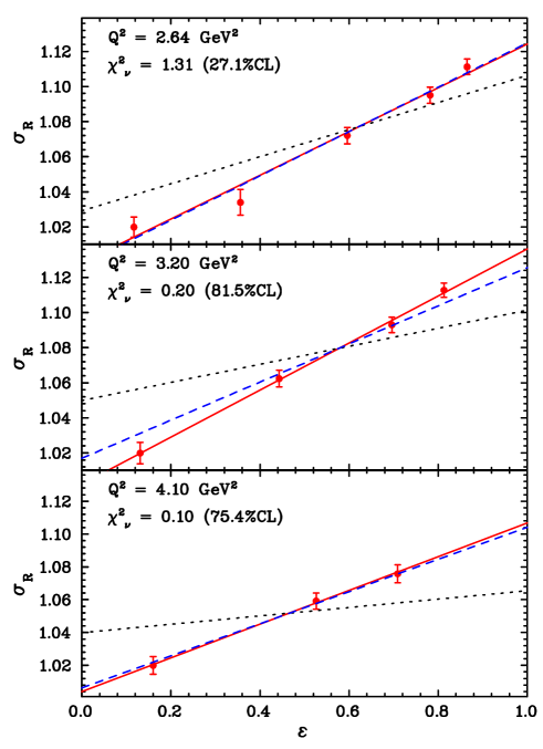
A number of authors [5] - [10] argue that the possible origin of these discrepancies is the failure of the one–photon approximation to precisely describe the results of unpolarized experiments. Indeed, with increasing the cross section of elastic scattering and especially the contribution of electric form factor drops down substantially. In such a case the contribution of two–photon exchange (TPE), which depends weakly on , can become considerable. Thus it was shown in [8] that allowing for the TPE in Rosenbluth technique, using a simplified model (which does not include nucleon excitations in the intermediate state), leads to a substantial change of form factors ratio, despite the small contribution of the TPE to the cross section (Fig. 3). This results from a strong dependence of the TPE contribution on electron scattering angle for a fixed [8].
Complications arising in the calculation of the TPE corrections are connected with difficulties in accounting for proton excitations in the intermediate state. The intermediate state contributions have been treated in a recent calculation at the quark-parton level, using generalized parton distributions to [10].
The Born amplitude is proportional to the lepton charge, , while the TPE amplitude is proportional to . The Born cross section is proportional to , while the interference term to the cross section goes like . Hence the interference term, which is the dominant part of the TPE contribution (since the TPE amplitude is small compared to the Born amplitude) changes sign with respect to the Born cross section and can therefore be determined by comparing electron–proton and positron–proton scattering.
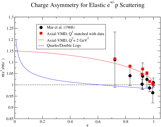
Attempts to measure the TPE contribution were made in the 1960s, but either the accuracy of the measurements was insufficient: %, where , or scattering angles were too small and therefore – where most theories predict , see Fig.4.
3 Experiment at VEPP–3.
We propose to perform a measurement of at the VEPP–3 storage ring at an energy of electron/positron beams of 1.6 GeV and at electron/positron scattering angles approximately , (corresponding to , and , )
There are several necessary preconditions for a successful realization of this experiment:
-
•
the injector delivering positrons at a rate 50 A/s (measured in VEPP–3 current);
-
•
the storage ring where electrons or positrons move in the same direction;
-
•
the experimental straight section with quadrupole lenses (to compress the beam) and with an internal gas target;
-
•
mean experimental luminosity (defined by positrons) can be rather high: , here – target thickness, – positron current averaged over a working cycle which includes storage phase, energy ramping phase, production phase and return-to-storage-mode phase. Storage phase for electrons is much less, as a result the cycle length is about a factor 1.6 smaller than that for positrons and the luminosity is larger by the same factor.
-
•
the equipment used at the previous experiment – particle detectors, data acquisition system, detector and target infrastructure, readout and slow control software as well as a large experience of conducting internal target experiments at VEPP–3 provides with a good basis for developing new target and detector and performing the measurements.
4 Target.
In previous experiments at VEPP–3 a polarized deuterium target was used. The luminosity was restricted by maximum achievable polarized target thickness of at/cm2, while electron beam current was limited (by large current effects) at a level of 140 mA. Mean luminosity was .
In the new target we are going to utilize a similar storage cell: having elliptical cross section 1324 mm, length 400 mm, cooled by liquid nitrogen. Hydrogen flux directed to the cell is going to be restricted at a level of at/sec, providing a target thickness of at/cm2. Note that gas density profile along the cell has a triangle shape with a maximum at/cm3 in the cell center and a base equal to the cell length (40 cm). With these target parameters two upper limits are reached simultaneously: first, with a higher gas flux the available vacuum pumps might not be able to maintain a required vacuum in the storage ring, second, for a thicker target the detector singles rates might become too high.
Let us also note that e.g. doubling the target thickness would result in only 30% increase of an average luminosity, because it is the time of positrons storing that takes up the main part of experimental time–cycle.
Gas flux to the storage ring vacuum chamber can be made about factor two lower (while retaining target thickness the same) by decreasing the temperature of the cell (down to ). This can be done using an appropriate cooler, but at present it is not available and has to be purchased.
A storage cell placed in the VEPP–3 ring would prevent beam injection into VEPP–4 and this may become a serious obstacle. That is why we are going to modify the design of the coupling between the cell and the straight section in order to be able to remove easily the cell from the aperture of VEPP–3 during VEPP–4 operations.
Optimal relation between beam storage time and data taking time in a timing cycle for positrons is shown in Table 1. Positron beam current will be changing from 50 mA down to 9 mA during the data taking phase. To decrease the systematic errors we are going to keep electron beam in the same range. But since the timing cycle for electrons is substantially shorter we will run two “electron” cycles for each “positron” cycle.
| phase | positrons | electrons |
| storage | 1630 | 10 |
| energy ramping | 300 | 300 |
| production | 1920 | 1920 |
| return to storage mode | 300 | 300 |
| sum for a single beam cycle | 4150 | 2530 |
| duration of a total cycle, which includes 3 beam cycles: | 9190 | |
5 Detector, event rate.
As was mentioned above, the detector for the measurement of () and () elastic scattering will be build on the basis of the detector used in the experiment that measured the deuteron form factors. Scattered electron and recoil proton will be detected in coincidence, which allows us to use kinematical correlations between their emission angles and energies, characteristic of two–body reactions. This is important for separation of the events from the process under study from those of various background processes.
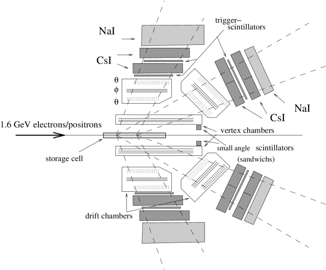
The detector (Fig. 5) is comprised of two identical systems placed symmetrically with respect to the storage ring median plane. Azimuthal angle acceptance of each system is 60o. Total –acceptance is = 120o, because particles can be detected either by upper or by lower system. Regarding the polar angles – electrons/positrons scattered at angles close to , , will be detected. These three –ranges are denoted later on as Small Angles (SA), Medium Angles (MA) and Large Angles (LA).
Electrons/positrons scattered at SA are detected by small scintillators (sandwiches). Recoil protons in this case are detected by LA–arms, where their trajectories and energies are measured. Here only part of extended target is “visible” to the detectors. Scattering at SA will be used as a luminosity monitor — as it was pointed out at small and the ratio should be very close to unity, i.e. . Application of two detector systems (upper and lower) not only increases the detecting solid angle but also allows to suppress systematic errors related to instability of the electron/positron beam position.
When electrons/positrons scatter to MA–arms, protons hit LA–arm detectors. For these events tracks and energies are measured for both particles. The experience obtained at previous experiments allows us to be sure that the information gathered by such detectors will be quite sufficient for a reliable event identification for scattering both at SA and at MA.
In addition, we plan to equip the LA–arms with electromagnetic calorimeters (there were no calorimeters here earlier). This is needed in order to measure the energy of electrons/positrons scattered at those angles, to separate the elastic electron/positron from pions or inelastic events. Note that in this case recoil protons are detected by MA–arm detectors. A minimal configuration of the calorimeters that can be assembled using CsI and NaI crystals, which we have at our disposal, is shown in Fig. 5.
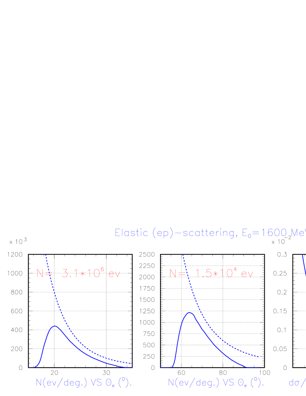
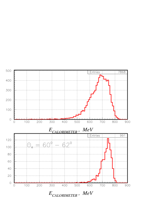
Cross section of (),() elastic scattering at LA is two orders of magnitude lower than that for MA. However, as it shown below, selection of the elastic scattering events can be done in this case as well, by measuring trajectories of both particles and electron energy at an accuracy provided by the calorimeters ( MeV, see Fig. 7).
6 Background estimation.
As it was mentioned above, difficulties in event selection may come out only for scattering at LA, where the cross section of elastic scattering becomes small ( nb/sr, see Fig. 6). Here we present an estimation of a background level from the processes which seem to be the most dangerous, namely electro- and photoproduction of pions.
Differential cross section of pion electroproduction can be written as [13]:
where is a flux of virtual photons, defined as:
Here is an invariant mass of the hadron system.
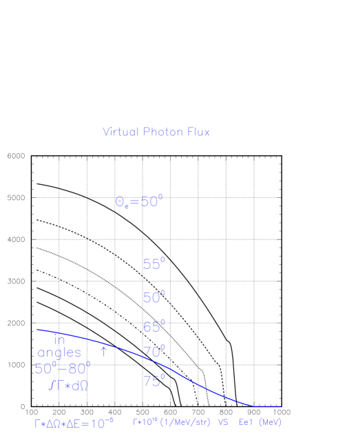
From Fig 8 one can see that after applying even a loose cut on scattered electron energy (e.g. MeV) a total flux of virtual photons would not exceed of a number of electrons deposited on the target. The cross section of the reaction is estimated to be , using data from [14, 15]. The cross section of the reaction is about the same. Therefore should not exceed . This is close to elastic scattering cross section, but applying cuts on the angular correlations specific to elastic scattering allows one to further decrease this background by two orders of magnitude.
Electron scattering at forward angle with pion production is usually considered as a process of pion photoproduction by equivalent photons. In this case there is only one charged particle (besides the undetected electron), therefore in order to get hits in tracking systems of both arms (from e.g reaction) it is required that a gamma-quantum from pion decay to be converted to a charged particle in materials on its way to wire chambers. Probability of such conversion () is small, estimated as .
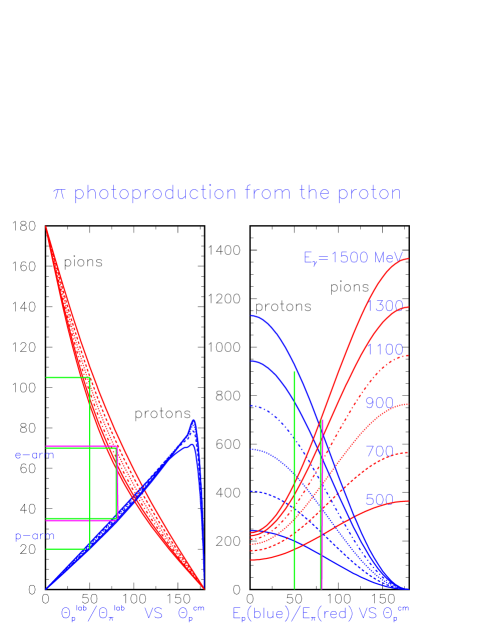
As one can see in Fig. 9, when a proton hits the MA–arm a is emitted in the direction of LA–arm and can be detected, providing the conversion occurred. A number of equivalent photons emitted by a beam’s electron (in energy intervals 100 MeV) is shown in Table 2 (second column) for various photon energies (first column). Cross section of pion photoproduction does not exceed [16]. Taking into account small one gets an event rate about the same as for elastic scattering (the last column in Table 2). However here again the background can be greatly reduced by applying angular correlation cuts.
It is also worth noting that a requirement to have a large energy deposition in LA–arm calorimeter is important to avoid confusing large–angle and medium–angle scattering events.
| (b/sr) | (nb/sr) | |||
|---|---|---|---|---|
| 500 | 0.0058 | 0.01 | 5 | 0.29 |
| 700 | 0.0034 | 0.01 | 5 | 0.17 |
| 900 | 0.0022 | 0.01 | 5 | 0.11 |
| 1100 | 0.0016 | 0.01 | 5 | 0.08 |
| 1300 | 0.0012 | 0.01 | 5 | 0.06 |
| 1500 | 0.0010 | 0.01 | 5 | 0.05 |
7 Experiment duration. Estimation of accuracy.
The experiment is divided into three phases, each requiring either VEPP–3 hall access or VEPP–3 operation:
-
1.
during shutdown of the VEPP–3 the following should be completed: installation of the straight section with gas target, obtaining the vacuum, commissioning the target, assembling and commissioning detectors, data acquisition system and target control system ;
-
2.
beam tuning: finding/restoring regimes of positron/electrons beam operation at VEPP–3, minimizing background — 7 days in total;
- 3.
Expected statistical accuracy in measuring is shown in Table 3. Below several possible sources of systematic errors are listed.
-
•
Unequal beam energy for electrons and positrons.
It is assumed that this difference can be made 1 MeV or less. Then / for three angle intervals will not exceed %, %, %. Using SA–arm data for normalization one can reduce this error by factor two. -
•
Different beam positions for electrons and positrons.
Sensitivity of / is estimated as %/mm, %/mm, %/mm for SA-, MA-, LA-scattering respectively. Beam positions will be monitored by current pick–up sensors with accuracy mm for relative position of electron/positron beams. Moreover already existing system for beam position stabilization can keep the beams orbit near the experimental straight section sable with same accuracy. Besides, one can see that SA–arms are very sensitive to the beam position, hence their count rates can be served as a beam position monitor. Finally since we have symmetrical arm pairs therefore by averaging count rates of up-arm and down-arm this effect can be suppressed in first order. Here an accuracy of /% can be achieved. -
•
Time instability of detectors efficiency.
This effect (like the previous one) is suppressed in first order because data collection with electron and positron beams will be alternated regularly. We expect that detectors efficiency would not change by more than 1% during one time cycle. Assuming that this instability has a random character, one would get a reduction of this error by averaging over many cycles. For 300 time-cycles the reduction will be , i.e. by over an order of magnitude. -
•
Drift of the target thickness in time. Special efforts will be devoted to achieve a stable gas flow during the whole experiment. And again using data rate of SA–arms as a monitor, and averaging over many cycles one should get a contribution of this effect to the systematic error of to be 0.1% or less.
Combining the above uncertainties, the total systematic error for the largest bin is expected to be constrained below /%. Therefore the measurement accuracy will be defined by statistical error.
| (o) | (GeV2) | (events) | % (stat) | % (sys) | |
|---|---|---|---|---|---|
| 10–12 | 0.08–0.11 | 0.98–0.98 | — | 0.30 | |
| 19–27 | 0.26–0.47 | 0.94–0.88 | 0.07 | 0.30 | |
| 60–80 | 1.40–1.76 | 0.51–0.32 | 1.00 | 0.30 |
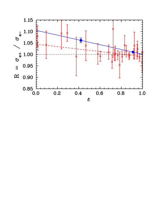
Calculations of the TPE effects indicate that the -dependence of the TPE correction is weak at large values. Analyses of the discrepancy between Rosenbluth and polarization transfer form factors also indicate a weak -dependence, and a change in the -dependence of 5–7% for 1–2 GeV2 [3, 6, 17]. Figure 10 shows the projected ratio and uncertainty, assuming an -dependence of roughly 5% in the electron cross section, yielding a slope of 10% in the ratio of positron to electron yield.
This work is supported in part by the U.S. Department of Energy, Office of Nuclear Physics, under contract W-31-109-ENG-38
References
- [1] M. N. Rosenbluth, Phys. Rev. 79 (1950) 615.
- [2] M. K. Jones et al., Phys. Rev. Lett. 84 (2000) 1398; O. Gayou et al., Phys. Rev. Lett. 88 (2002) 092301.
- [3] J. Arrington, Phys. Rev. C 68, (2003) 034325 and arXiv:nucl-ex/0305009.
- [4] J. Arrington, “New measurement of of the proton,” International Workshop EEP03, 14-17 October 2003, Grenoble, France, arXiv:nucl-ex/0312017.
- [5] M. P. Rekalo and E. Tomasi-Gustafsson, arXiv:nucl-th/0312030.
- [6] P.A.M. Guichon and M. Vanderhaeghen, Phys. Rev. Lett. 91 (2003) 142303 and arXiv:hep-ph/0306007.
- [7] J. Arrington, Phys. Rev. C 69, (2004) 032201 and arXiv:nucl-ex/0311019.
- [8] P. G. Blunden, W. Melnitchouk and J. A. Tjon, Phys. Rev. Lett. 91 (2003) 142304 and arXiv:nucl-th/0306076.
- [9] A. Afanasev, S. Brodsky and C. Carlson, presented by A.Afanasev at the DNP Meeting, Tucson, AZ, Oct. 2003.
- [10] Y. C. Chen, A. Afanasev, S. J. Brodsky, C. E. Carlson, and M. Vanderhaeghen, arXiv:hep-ph/0403058.
- [11] J. Mar et al., Phys. Rev. Lett. 21 (1968) 482.
- [12] K. Joo et al., “Two–photon exchange from a precise comparison of e+p and e-p elastic scattering in CLAS,” Letter of Intent to PAC 25, TJNAF, 2004.
- [13] F.Foster, and G.Hughes, “Electroproduction of nuclear resonances”, Rept. Prog. Phys. 46 (1983) 1445.
- [14] V.V.Frolov et al., Phys. Rev. Lett. 82 (1999) 45.
- [15] Hovanes.Egiyan, Ph.D. Thesis, The College of William and Mary in Virginia,(2001) (unpublished).
- [16] B. Krusche et al., Eur. Phys. J. A 6 (1999) 309.
- [17] J. Arrington, Phys. Rev. C 69 (2004) 022201 and arXiv:nucl-ex/0309011.