Active optical fibres in modern particle physics experiments
Abstract
In modern particle physics experiments wavelength-shifting and scintillating fibres based on plastic polymers are used for tracking and calorimetry. In this review the role of photon trapping efficiencies, transmission functions and signal response times for common multimode active fibres is discussed. Numerical simulations involving three dimensional tracking of skew rays through curved fibres demonstrate the characteristics of trapped light. Of practical interest are the parametrisations of transmission functions and the minimum permissible radius of curvature. These are of great importance in today’s experiments where high count rates and small numbers of photoelectrons are encountered. Special emphasis has been placed on the timing resolution of fibre detectors and its limitation due to variations in the path length of generated photons.
I Introduction
Optical fibres with large core diameters, i.e. where the wavelength of the light being transmitted is much smaller than the fibre diameter, are commercially available and readily fabricated, have good timing properties and allow a multitude of different designs. Multimode fibres are useful for short data-bus connections, local area networks and for multiplexing and sensor technologies. Since their first appearance in charged particle detectors of the early 1980s active optical fibres have also played an important part in the field of nuclear and particle physics. Optical fibres are commonly produced from glass, plastic and synthetic fused silica, often called silica or quartz fibre. Each type has its own advantages and drawbacks. Early glass materials were based on Cerium (Ce3+ oxide) and have attracted some attention. For charged particle detection, plastic scintillator compositions have been emerged as the far superior material. In contrast, for data communications applications, silica fibre is the overwhelming choice. Nowadays, the low costs of plastic base materials make it possible for many particle physics experiments to use plastic fibres in large quantities.
Light is generated inside an active fibre either through interaction with the incident radiation (scintillating fibres) or through absorption and re-emission of primary light (wavelength-shifting fibres). A small fraction of the emitted light is guided via total internal reflection to the fibre end where it is detected by visible-light photon sensors. The great interest in fibres is based on the fast signal response of organic scintillators and the high spatial precision and easy handling of fibres. As the output signals of many photon sensors are short on the time-scale of electronic circuits and data acquisition systems, these detectors can be operated at high count rates. In case the active fibres are located inside a strong magnetic field region, the fibres can be spliced on clear fibres that have a higher transmission, so that the photon sensors can be placed outside the field region. This is also done if the active area of a scintillating fibre detector has to be restricted to minimise background count rates.
In response to the need for precise and fast detectors Borenstein reported on the properties of plastic scintillating fibres in the year 1981. His group had measured decay constants of a few nanoseconds in fibres. In these years, development work was focused on vertex detectors for fixed target experiments. In addition, some experiments used scintillating fibres as active targets for the study of rare processes. Active targets were formed from coherent arrays of scintillating glass fibres, plastic fibres, or capillaries filled with liquid scintillators and the targets were viewed by image intensifiers. Throughout the 1980s and 1990s substantial efforts have been devoted to the development of better glass and plastic scintillation materials and the detection of ionising radiation with scintillating fibres has been generally practised in many different ways. The main applications of active fibres in the present generation of particle physics experiments are large-area tracking detectors and fine-sampled calorimeters.
Trackers are sub-detectors which surround the interaction point to reconstruct charged particle tracks and their vertex positions at lepton or hadron accelerators. A modern system can be found at the Fermi National Accelerator Laboratory where the D Central Fiber Tracker comprises 71,680 multi-cladding fibre channels [1]. One of the most exhaustive of all fibre systems is the CHORUS tracker [2]. It is based on a total of about 1.2 million plastic scintillating fibres of 0.5 mm diameter which are read-out via an opto-electronic system comprising image intensifier tubes and CCD cameras (Charged Coupled Devices) in series. The long baseline neutrino oscillation experiment K2K also employs, as a component of its near detector, a scintillating fibre tracker with 274,080 fibres in total [3]. For its signal processing groups of 11,420 fibres are glued together to make single bundles of 12 cm diameter each with an opto-electronic read-out system similar to the CHORUS one. For the construction of the highly segmented tracker of the ATLAS experiment more than 600,000 wavelength-shifting fibres have been used [4]. For fibre trackers the basic element is a fibre doublet ribbon, which is formed from two single layers of fibres, with one of the fibre layers set off relative to the other by half a fibre spacing. The stacking of fibres provides a higher light yield per channel and enough spatial overlap to avoid relying on the detection of events with only a grazing contact with the charged particle. A charged particle which crosses the gap between two fibres in one of the layers is likely to traverse the full fibre diameter in the other layer. It has been shown that a high detection efficiency and a good spatial resolution can be achieved with multiple doublets. The good timing resolution of such tubes enables a higher level event-selection in the early stage of the trigger of large detector systems. Used in conjunction with other detectors like calorimeters or muon spectrometers, such trigger can provide a powerful signature for identification of electrons, muons, photons and event vertices. Accordingly, multi-layered structures of stacked scintillating fibres coupled to multi-anode photomultipliers became the preferred choice for some fast trigger detectors, the COMPASS trigger [5] being one recent example.
Fibre calorimeters consist of dense absorber materials sampled with scintillating fibre planes to achieve a very compact geometry. Fibre calorimeters are found, for example, in the muon (g-2) experiment [6] at Brookhaven and in the KLOE detector [7] at the DANE accelerator of the INFN LNF, where lead foils are interleaved with layers of scintillating fibres. In some cases, bulk scintillators are read out via wavelength-shifting fibres, most recently in the MINOS experiment [8] where fibres are embedded in 8 m long scintillating bars. The approved experiments for the LHC collider at CERN are relying heavily on active fibres, too. The LHCb experiment uses 6000 detector cells with wavelength-shifting fibre read-out [9] and the CMS experiment uses wavelength-shifting fibres embedded in scintillator plates for its sampling hadronic calorimeter [10]. Fibre calorimeters can achieve energy resolutions comparable to full absorption calorimeters.
At high luminosity accelerators a new generation of magnetic spectrometers is being developed for fixed target experiments to reveal the nucleon structure with electromagnetic probes. Up to now large magnetic spectrometers have mainly used various types of wire chambers as coordinate detectors for momentum determination in the dispersive plane. But these detectors are slow and in the high particle flux environments of the high luminosity accelerators very fast detectors are indispensable. Furthermore, active elements of low density with long radiation and interaction lengths are necessary to avoid multiple scattering and energy loss of particles. For the same reason, mounting structures and other inactive materials have to be minimised within the detector system’s volume. These requirements can be met by stacks of scintillating fibres which are a good compromise between signal to noise ratio and trigger or tracking efficiency on the one side and the amount of material traversed by the particles on the other side. Alternative detector concepts include the newly developed carbon plated kapton straw tubes with minimised drift times. In addition, there has been an impressive progress during the last couple of years on gaseous micro-pattern detectors. These detectors have much higher rate capabilities than wire chambers. In a detector called Micromegas the gas amplification happens between a metal mesh several m thick and a printed circuit board with metal strips about 0.2 mm apart [11]. Another detector called Gas Electron Multiplier (GEM), first introduced in November 1996 by Sauli [12], is very promising. Its key element is the GEM electrode, consisting of a polymer film about 50 m thick, metallised on both sides, with a regular array of small holes. For a spacing of 140 m the holes have diameters of about 70 m. In stacks of several GEMs amplification and induction gaps are separated and very high gas amplifications can be reached. Another type of detector to be considered as competitive to conventional detector concepts in future fixed target experiments are silicon micro-strip or micro-pad detectors. These are the detectors of choice for the LHC experiments ATLAS and CMS. They provide an extremely good spatial resolution but their timing resolution is limited to ns by the signal to noise ratio of the solid state element. Another disadvantage of such detectors is their relatively large thickness. From the above discussion one may conclude that the fastest coordinate detectors presently available—scintillating fibres—are playing a decisive role for the latest experiments in hadron physics where luminosities and particle fluxes are challenging.
Thus, the interest in active fibres by experimental particle physicists is large. In recent years, additional applications have emerged in medical and biological dosimetry, in electron or ion beam monitoring, in activity studies of radioactive waste, and in X-ray and synchrotron radiation detection. In contrast, the basic theory describing the propagation of photons in fibres is not commonly known to particle physicists. The strict treatment of small diameter optical fibres involves electromagnetic theory applied to dielectric waveguides, which was first achieved by Snitzer [13] and Kapany [14]. This is not a simple undertaking, especially for bent fibres where an eigenvalue equation is not available. To solve this problem many approximation techniques have been developed which are reasonably accurate for single-mode fibres. In multimode fibres, however, the electromagnetic fields get substantially modified by any curvature [15]. Light losses in small diameter fibres with uniform curvature have been calculated numerically but the method becomes extremely difficult for fibres of large diameters. Although these approaches provide insight into the phenomenon of total internal reflection and eventually lead to results for the field distributions and the radiation from curved fibres, it is advantageous to use ray optics for large diameter fibres where the waveguide analysis is an unnecessary complication. The optics of meridional rays in fibres was developed in the 1950s [16] and can be found in numerous textbooks, e.g. [17, 18, 19]. Since then, the scientific and technological progress in the field of fibre optics has been enormous.
This paper is organised as follows: section 2 starts with a review of active optical fibres in the field of detection and measurement of ionising radiation and charged particles. In section 3 a simulation code is outlined that performs a three-dimensional tracking of light rays in cylindrical fibres. The first part of section 4 discusses the trapping of light rays and the quantitative distinction between skew and meridional rays. Then, it continues with a comprehensive overview on the light yield of active fibres where special emphasis is placed on light losses in sharply curved fibres. The chapter ends with a paragraph on the radiation resistance of plastic fibres. The timing resolution of active fibres is an important and prevailing issue that is presented in section 5. Finally, the conclusions review the current research on active fibres for modern particle physics experiments. References on latest developments in scintillating fibre technology are given throughout the text as they apply to charged-particle detection.
II General discussion
For charged particle detection mostly fibres produced from plastic polymers are used. For several reasons they are better suited than alternative candidates. For example, they have intrinsically higher efficiency, faster signal response times, and lower material densities. In general, a typical fibre consists of a core coated with a thin (m) transparent cladding with a smaller index of refraction than the core has. The plastic cores of active fibres include several components. The base material ( by weight) is an organic polymer, such as polystyrene (PS) or polyvinyltoluene (PVT). It is doped with organic molecules, mostly aromatic compounds, which emit scintillation***Scintillation is an example of radioluminescence. Scintillators may be organic and inorganic solids, liquids, and gases. light. Total internal reflection at the core-cladding interface allows for an efficient transport of light over many metres. The cladding itself provides a protective layer around the fibre core. A fibre with the refractive index constant over the fibre core cross-section is called a step index fibre. The most common type of fibre used in particle physics consists of a polystyrene-based core of refractive index 1.6 and a thin polymethylmethacrylate (PMMA, C5H8O2) cladding of refractive index 1.49 (indices are given at a wavelength of 590 nm). Throughout this paper I will refer to this formulation as “standard”. A more recent cladding material is fluorinated methylmethacrylate (MMA) with 1.42. Single MMA cladding fibres have shown a poor performance in terms of absorption and mechanical stability, so that MMA now is only used in double cladding fibres. These have an inner PMMA cladding and an outer MMA cladding, which leads to a significantly increased trapping efficiency and light yield. In figure 1 a cross section through a double cladding fibre is shown to illustrate the cone of trapped light in the meridional approximation. For a double cladding fibre the critical axial angle is given by . In principle an active cladding is possible, but uncertain mechanical compatibility issues between the core and a chemically modified cladding have prevented such a development up to now. In this paper I will consider round fibres only, since edged cross-sections tend to entail in the manufacturing process serious problems of homogeneity at the edges. Typical diameters of fibres used in calorimetry are in the range of 0.5 – 1.5 mm, for tracking detectors the diameter is of the order of 10 – 100 m. Obviously, the fibre dimensions together with their geometrical overlap define the spatial precision of a tracker. An early work on active plastic fibres can be found in [20]. In the year 1995, Leitz [21] wrote an excellent review of scintillating fibres in particle physics, including working conditions of fibres, the scintillation process and photoelectron counting.
After the passage of a charged particle many of the atoms in the medium will be excited into higher energy levels. The electronic levels have a typical energy spacing of eV. Transitions from the ground state to the excited state occur with no change in interatomic distance. The excited molecule quickly loses vibrational energy to arrive in an electronic state S∗. In non-scintillating materials the excitation energy is given up in the form of heat or lattice vibrations. In a scintillator, however, some of the excitation energy is released as electromagnetic radiation. These compounds contain bound benzene rings, e.g. p-terphenyl. The electronic state S∗ of a scintillator decays to some vibrational level of the ground state within a characteristic decay time, ns. The emitted light is not self-absorbed as the light propagates along the fibre by a further S S∗ transition because of the differing shapes of the excited and ground state energy levels as a function of interatomic spacing. The net result is a disparity between the absorption and the emission spectrum of the molecule, where the details of both spectra are governed by the electronic structure of the molecule. The difference between the wavelengths of the peak positions is called Stokes’ shift. It is the excitation of the electrons within the -orbitals that results in the scintillation.
In polystyrene the absorption peak is far from the p-terphenyl emission, although the base is opaque to this light because of Rayleigh scattering. Usually, the base scintillators are not good intrinsic light transmitters. The fluorescence yield, that is the ratio of the number of excited atoms which emit a photon to the total number of excited atoms, of pure polystyrene is rather poor, . A shift of the emission light into the base material’s transparent region (nm for polystyrene) can be achieved by adding a fluorescent dopant to the monomers of the core base material for combined polymerisation. Most modern fibres are working with a one-component system (3HF or PBBD), where the sufficiently high concentration (molar fraction ) of the dopant allows local, non-radiative Förster transitions from the excitation site to the dopant. Förster transitions are fast (ns) and resonant dipole-dipole transitions. Thereafter, the excitation energy is stored in the excited dopant molecule. Usually, the dopant is chosen to have a large Stokes’ shift which leads to a small self-absorption of the secondary light. The fluorescence yield can be enhanced to values of . Several families of compounds with these properties (fast, efficient, and low self-absorption) have been found. Among these are the hydroxyflavons, hydroxybenzothiazoles and hydroxybenzoxazoles, from which 3HF (3-hydroxyflavone) has been produced.
Some dopants like p-terphenyl or PBD need additional wavelength-shifting components in very low concentrations, for example 1,4-di-(2-(5-phenyloxazolil))-benzene (C24H16N2O2), called POPOP, or bPBD (C18H14). Their absorption bands overlap the emission band of the primary dopant and the primary light is absorbed by the wavelength shifter before it can get attenuated by other processes. The self-absorption of the secondary light is smaller than the self-absorption of the primary light because of the low concentration (molar fraction ) of the wavelength-shifting molecules. The minimal self-absorption also helps to eliminate cross-talk between neighbouring fibres and the long emission wavelengths provide improved immunity to the effects of radiation damage. More details of the scintillation process are discussed in depth by Birks [22].
Wavelength-shifting fibres are very similar in structure to the scintillating fibres discussed earlier. A wavelength-shifting fibre uses a non-scintillating base material doped with a fluorescent dye to shift external light from a scintillator to longer wavelengths. The most common formulation is an absorption peak in the blue region of the spectrum and an emission peak in the green or yellow region, where a wide spectral overlap between the emission spectrum of the scintillator and the absorption spectrum of the wavelength-shifting fibre is necessary. The fibres may be positioned in grooves machined into the surface of plastic scintillators bars. The quantum efficiency of the wavelength-shifter is usually high, i.e. in the range of %.
In the fibre core a certain fraction of the scintillation light, called core light, is trapped by total internal reflections at the core-cladding interface. Light not trapped in the fibre core is refracted into the cladding and again some portion of this light is trapped by total internal reflections at the cladding-air interface, called cladding light. Because of the stepping refractive indices the trapping efficiency for cladding light is much larger than the one for core light. In general, the relative contribution of each light component depends on the distance of the detector from the emission point and the attenuation lengths. Most light detected after short fibre lengths can be related to the cladding light, but the cladding light is attenuated to a greater degree than the core light. The losses of cladding light are mainly caused at the cladding-air interface which is exposed to the environment and therefore will degrade by abrasion or accumulation of impurities. The removal of the cladding light can be useful and is accomplished by coating the fibre with an extra-mural absorber. It is also known that internal reflections being less than total give rise to so-called leaky or non-guided modes, where part of the electromagnetic energy is radiated away at the reflection points. An extra-mural absorber eliminates those components together with most of the cladding light. Sometimes a diffuse reflecting paint, usually TiO2, is used for gluing stacks of fibres together. In these applications the extra-mural absorber suppresses optical cross-talk between adjacent fibres, which occurs when untrapped photons, i.e. about 90% of all light, are trapped in neighbouring fibres after being scattered. A trapped ray may be categorised by its path along the fibre. The path of a meridional ray is confined to a single plane, all other modes of propagation are known as skew rays. The projection of a skew ray on a plane perpendicular to the fibre axis changes its orientation with every reflection. In the special case of a cylindrical fibre all meridional rays pass through the fibre axis.
The short and fast light pulses of active fibres are detected by photo-effect based light detectors. Several sensors for the detection of the fibre light have been investigated. In most cases the detection is performed by means of conventional photomultiplier tubes. Their photocathodes are mainly composed of semi-conducting photo-emissive materials (bialkali, trialkali and others) which are evaporated as thin films on the inside of optic front windows. The quantum efficiency of a typical photocathode is good () in the blue spectral region and fair to poor () in the yellow and green region. This combination of fast active elements with modern read-out devices entails the characteristics of low noise, large gain, good linearity and good timing resolution. The details of the coupling depend strongly on transmission range and refractive index of the window material and on the quantum efficiency of the photocathode. The refractive index of front windows ranges from 1.4 (LiF) over 1.5 (crown glass, borosilicate, quartz) to 1.95 (YalO3), the transmission edge ranges from 120 to 350 nm. Mineral oils and optical couplants have been used successfully as optical coupling media bridging the difference in refractive indices. For most fibre to photomultiplier interfaces transmission values above 95% are readily achieved. Losses can occur because of longitudinal, lateral and angular misalignment.
Position-sensitive photomultipliers are especially suitable for fibre read-out because of the good match between photomultiplier segmentation and common fibre diameters, offering an important reduction in size and cabling with respect to conventional tubes. Since the pioneering work of Kuroda [23] such tubes have been developed in order to meet the demands on precise and reliable tracking devices under high-rate circumstances [24, 25, 26]. In recent years they have been continously improved. In modern experiments, fibre bundles involving a rather large number of channels are easily read out via position-sensitive photomultipliers, while the use of single channel photomultipliers is no longer economical in terms of cost and space requirements. Three different types of position-sensitive photomultipliers are in use: a) multi-anode photomultiplier with a grid-like dynode structure and segmented anode pixels, (b) multi-dynode photomultiplier with a separate dynode structure for each channel and (c) multi-channel photomultiplier where each channel additionally has its own photocathode and glass window. The two most important parameters to characterise position-sensitive photomultipliers is the amount of cross-talk between adjacent channels and the channel to channel gain variations. The first generation of position-sensitive photomultiplier tubes suffered from high cross-talk and large gain variations.
The Hamamatsu Photonics [27] R5900 series is a rather new development which has been chosen by many groups, e.g. the MINOS collaboration [8], as their fibre read-out device. The performance of this tube was first reported in [28] and many comprehensive tests have been conducted since then, see e.g. [29]. The drawbacks of early position-sensitive photomultipliers have been greatly reduced; the tube exhibits very little cross-talk and a high gain uniformity between channels. It comes in a very compact design and six different anode geometries suitable for fibre read-out, one particularly useful type of anode shape is the M-16, in which the mm2 bialkali photocathode is divided into 16 pixels each with a sensitive area of mm2 per pixel. The cathode is followed by individual metal channel dynodes incorporating 10 to 12 stages and the output signal is read out from independent multiple anodes. Single fibres or bundles of up to seven fibres can get coupled to one pixel.
Photomultiplier tubes are limited in their intrinsic energy resolution by fluctuations in the number of secondary electrons produced at the first dynode. This limitation can be overcome by using hybrid photomultiplier tubes with their excellent multiple photon separation and high efficiency. A hybrid photomultiplier tube consists of a reversely biased silicon P-I-N diode, in which highly accelerated photoelectrons create a few thousand electron-hole pairs with much smaller statistical fluctuations. The quantum efficiency of silicon photodiodes can be as high as 70% for visible wavelengths. In special cases, image intensifiers with CCD cameras, solid state photomultipliers or so-called Visible Light Photon Counters (VLPC) have been employed in active fibre read-out. The VLPC has been developed by Rockwell Int. Science Center and is used e.g. in experiment E835 at the Fermi National Accelerator Laboratory [30]. It can reach 85% quantum efficiency. Some studies on silicon based avalanche photodiodes have been performed [31] and it was demonstrated that it is possible to use this type of photodiodes for room-temperature fibre read-out, too. The diodes consist of a compact semiconductor element operated with at reverse bias voltage near the breakdown voltage. The basic structures include an absorption region and a multiplication region with a high electric field. The multiplication region is broad enough to provide a useful gain of at least 100 by impact ionisation. Recently, there has been some progress in improving gain and stability and first arrays of avalanche photodiodes have become available to cope with a large number of fibres closely lined up.
The signal amplitude from a fibre detector, quantified by the number of detected photoelectrons, is a complex factor involving the light output of the fibre, the light collection efficiency, the coupling of the fibre to the photon sensor, and the sensor’s characteristics. In many applications the number should be as large as possible to discriminate the signal against dark pulses and electronic noise. It is instructive to work through a numerical estimate. The following example gives a parametric factorisation of the signal amplitude for a scintillator bar with a wavelength-shifting fibre of approximately 3 m length, read out with a multi-anode photomultiplier. The scintillator bar is exposed to a uniform illumination of charged particles from one direction at normal incidence at the far end of the scintillator. The source of the signal is the luminescence of the scintillator, numerically equal to the number of scintillation photons produced at the site of ionising radiation. It can be estimated by:
| (1) | |||||
| (2) |
where a mean energy deposition corresponding to minimum ionising particles MeVcm2, the density of plastic scintillator gcm3, the average path length of a charged particle traversing the scintillator of height cm, and an absolute light yield, , of 10,000 photons produced per MeV of deposited energy in polystyrene is assumed. The light yield corresponds to 1 excitation per 4.8 eV and a quantum efficiency of the scintillator.
The light collection and transfer factor, , of a scintillator bar is of the order of 50%. It is dependent on the geometry and the effective attenuation length of the scintillator, , the reflectivity of the scintillator surface, , and the number of fibres per scintillator bar, . For complicated geometries the exact number may be evaluated by Monte Carlo simulations. In case of a simple geometry it can be estimated. In infinite long bars the probability of a photon to hit a fibre of diameter can be written as where is the distance between adjacent fibres, in this example identical to the width of the bar, . The probability of a photon being absorbed in the scintillator is simply , where is the path length of the photon between two fibres. The probability for the photon not to be reflected can be written as . This leads to a light collection efficiency of
| (3) |
In this model the increase in light yield when using two fibres instead of one is equal to . The simple model has been verified to be sufficiently accurate by using a ray tracing code to find the fraction of scintillation photons which are absorbed in a wavelength-shifting fibre located in a groove in a rectangular scintillator.
Photons are emitted isotropically within the fibre. Using the meridional approximation the trapping efficiency for core light emitted in one axial direction of the fibre is for a single cladding fibre. For this example the transmission functions of fibre and photomultiplier entrance window are assumed to be and . The emission spectrum is a characteristic of the scintillation material and the spectral quantum efficiency of the detector is a characteristic of the photocathode. An wavelength averaged value of is reasonable. Finally, the number of photoelectrons in a typical fibre experiment can be estimated by combining the above values:
| (4) |
Hence, a typical detected photoelectron yield is of the order of . This value is consistent with measurements.
III Three-dimensional Tracking of Light Rays
To illustrate the characteristics of trapped light I use results from a programme which simulates emission and propagation of light rays. The motivation for writing the programme was to understand the loss of light in sharply curved fibres. Since the analytic analysis of the passage of skew rays along a curved fibre is exceedingly complex, a Monte Carlo technique had to be applied. This type of numerical integration using random numbers is a standard method in the field of particle physics and is now practical given the CPU power currently available. Detailed results of this programme on the light acceptance and propagation in straight and curved multimode active fibres can be found in [32].
A light ray is followed by the simulation until it is absorbed or detected. Quantities to be delivered by the programme are the proportion of light detected, and the arrival time distribution, or the various ways light rays may be lost. On its path the ray is subject to attenuation, parameterised firstly by an effective absorption coefficient and secondly by a reflection coefficient. At the core-cladding interface the ray can be reflected totally or partially internally. In the latter case a random number is compared to the reflection probability to select reflected rays.
Light rays are randomly generated on the circular or rectangular cross-section of a fibre with radius or width and height . An arbitrary ray is defined by its axial and azimuthal or skew angle. An advantage of this method is that any distribution of light rays can easily be generated. The axis of the fibre is defined by a curve where is the arc length. For , it is a straight fibre along the negative -axis and for , the fibre is curved in the -plane with a radius of curvature . In particular, the curve is tangential to the -axis at .
Light rays are represented as lines and determined by two points, and . The points of incidence of rays with the core-cladding interface are determined by solving the appropriate systems of algebraic equations. In the case of a straight fibre the geometrical representation of a straight cylinder or box is used resulting in a quadratic equation. Its positive solution defines the point of incidence, , on the fibre wall. In the case of a cylindrical fibre curved in a circular path, the cylinder equation is generalised by a torus equation. The coefficients of this fourth degree polynomial are real and depend only on and the vector components of and up to the fourth power. In most cases there are two real roots, one for the core-cladding intersection in the forward direction and one at if the initial point already lies on the cylinder wall. The roots are found using Laguerre’s method [33]. It requires complex arithmetic, even while converging to real roots, and an estimate for the root to be found. The routine implements a stopping criterion in case of non-convergence because of round-off errors. The initial estimate is given by the intersection point of the light ray and a straight cylinder that has been rotated and translated to the previous reflection point. A driver routine is used to apply Laguerre’s method to all four roots and to perform the deflation of the remaining polynomial. Finally the roots are sorted by their real part. The smallest positive, real solution for is then used to determine the reflection point, .
After the point of incidence has been found, the reflection length and absorption probability can be calculated. The angle of incidence, , is given by , where denotes the unit vector normal to the core-cladding interface at the point of reflection and is the unit incident propagation vector. Then, the reflection probability corresponding to this angle is determined. In case the ray is partially or totally internally reflected, the total number of reflections is increased and the unit propagation vector after reflection, , is calculated by mirroring with respect to the normal vector: . The programme returns in a loop to the calculation of the next reflection point. When the ray is absorbed on its path or not reflected at the reflection point, the next ray is generated. At any point of the ray’s path axial, azimuthal and skew angle are given by scalar products of the ray vector with the coordinate axes in a projection on a plane perpendicular to the fibre axis and parallel to the fibre axis, respectively. The transmitted flux of a specific fibre, taking all losses caused by bending, absorption and reflections into account, is calculated from the number of lost rays compared to the number of rays reaching the fibre exit end.
This method gives rise to an efficient simulation technique for fibres with constant curvature. It is possible to extend the method for the study of arbitrarily curved fibres by using small segments of constant curvature. In the current version of the programme light rays are tracked in the fibre core only and no tracking takes place in the surrounding cladding, corresponding to infinite cladding thickness. For simplicity only monochromatic light is assumed in the simulation and highly wavelength-dependent effects are not included explicitly. The simulation code takes about 1.5 ms to track a skew ray through a curved fibre.
IV Light Yield—Trapping of Light
In practical applications, the light yield is the most important criterion for the design of a fibre detector. Any deficiency in this respect reduces detection efficiency, compromises timing resolution and restricts total fibre length. Due to the small cross-section of fibres the light yield is intrinsically low. Whether the fibres are scintillating or wavelength-shifting one is only ever concerned with a few 10’s or 100’s of photons propagating in the fibre and a single photon counting capability is often necessary. With increasing dopant concentration the light yield increases, but above a certain limit self-absorption of the emitted light reduces the attenuation length noticeable. Accordingly, fibres with various concentrations of fluorescent dyes have been systematically tested since 1992. For all commercially available fibres an optimum has been found and no further improvements from adjusting the dopant concentrations can be expected. Thus, the trapped light as a fraction of the intensity of the emitted light and the transmission function have the largest impact on the light yield of an active fibre.
A Angular Phase Space of Trapped Light
The geometrical path of any rays in cylindrical fibres, including skew rays, was first analysed in a series of papers by Potter [34] and Kapany [35]. The treatment of angular dependencies in this paper is based on their approach. The angle is defined as the angle of the projection of the light ray in a plane perpendicular to the axis of the fibre with respect to the normal at the point of reflection. One may describe as a measure of the “skewedness” of a particular ray, since meridional rays have this angle equal to zero. The polar angle, , is defined as the angle of the light ray in a plane containing the fibre axis and the point of reflection with respect to the normal at the point of reflection. It can be shown that the angle of incidence at the core-cladding interface of the fibre, , is given by . The values of the two orthogonal angles and will be preserved independently for a particular photon at every reflection along its path.
In general, for any ray to be internally totally reflected within the fibre core, the inequality must be fulfilled, where the critical angle, , is given by the index of refraction of the fibre core, , and that of the cladding, . For the further discussion in this paper it is convenient to use the axial angle, , as given by the supplement of , and the skew angle, , to characterise any light ray in terms of its orientation. A skew ray can be totally internally reflected at larger angles than meridional rays and the relationship between the minimum permitted skew angle, , at a given axial angle is determined by the critical angle condition: . In the meridional approximation the above equations lead to the well-known critical angle condition for the polar angle, , which describes an acceptance cone of semi-angle with respect to the fibre axis (see for example [34] and references therein). Thus, in this approximation all light within the forward cone, which experiences multiple total internal reflections, will be considered as trapped.
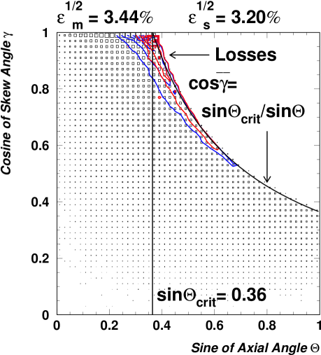
Figure 2(a) shows the total acceptance domain, i.e. the angular phase space of possible propagation modes, and the phase space density, i.e. the number of trapped photons per angular element , which is represented by proportional boxes. Photons have been generated randomly on the cross-section of the fibre with an isotropic angular distribution in the forward direction. The density increases quadratically with and linear with . To the left of the dividing line at all skew angles are accepted. To the right of the line a minimum skew angle is required by the critical angle condition. The phase space contours in this figure relate to sharply curved fibres. They show the distribution of photons which are trapped in a straight fibre section but get refracted out of sharply curved fibres with a radius of curvature to fibre radius ratio, , of 33 and 83. The contours demonstrate that only photons from a small region close to the phase space boundary are getting lost. The smaller the radius of curvature, the larger the affected phase space region. Figure 2(b) shows a projection of the phase space onto the -axis. A peak around the value of is apparent.
B Trapping Efficiency
The trapping efficiency for forward propagating photons, , may be defined as the fraction of totally internally reflected photons. Figure 2(a) gives values for the two trapping efficiencies which have been determined by integrating the phase space density over the two angular regions. The trapping efficiency can also be determined analytically by two integrals [36] for the flux transmitted by a fibre:
| (6) | |||||
where is the element of solid angle, refers to the maximum axial angle allowed by the critical angle condition, is the radius of the fibre and is the angular distribution of the emitted light in the fibre core. The two integrals, and , refer to the meridional and skew case, respectively. The lower limit of the integral is given by .
For an isotropic emission of fluorescence light the total flux through the cross-section of the fibre core, , equals . Then, dividing the first term of equation (6) by the total flux gives the trapping efficiency in the meridional approximation,
| (7) |
where all photons are considered to be trapped if . Contributions of all skew rays to the trapping efficiency are given by
| (8) |
The total trapping efficiency is then:
| (9) |
which equals for small critical angles approximately twice the trapping efficiency in the meridional approximation. This trapping efficiency is crucially dependent on the circular symmetry of the core-cladding interface. Any ellipticity or variation in the fibre diameter will lead to the refraction of some skew rays. Skew rays get also attenuated more quickly, so that the trapping efficiency of skew rays does not contribute to the light yield of a fibre in the same way as the trapping efficiency of meridional rays does. In conclusion, for long fibres the effective trapping efficiency is closer to than to .
The trapping efficiency for cladding light is determined by replacing with and with the refractive index of the surrounding medium, , in the above formulae. Thus, the critical angle changes to . The cladding component of the trapped light is the difference . This cladding light is usually a factor 3–4 more intense than the core light. While this is highly desirable in terms of light yield, it leads to a larger cross-talk between fibres of a bundle. Furthermore, cladding light is heavily affected by the external surface quality of the fibre: cracks in the cladding or defects in the surface can cause significant light losses leading to huge differences in the light yield of otherwise identical fibres.
Formula 7 gives a meridional ray trapping efficiency of 3.44% for “standard” fibres with 1.6 and 1.49; the skew ray efficiency in formula 8 evaluates to 3.20% and the combined core efficiency in formula 9 to 6.64%. The efficiency for cladding light neglecting any absorption equals 23.83%. For square fibres the core cladding efficiency is somewhat larger, the simulation calculates a value of 8.13%.
It is obvious from the critical angle condition that a photon emitted close to the cladding has a higher probability to be trapped than when emitted close to the centre of the fibre. Scintillation photons are distributed uniformly in solid angle. For a given axial angle the range of possible azimuthal angles for the photon to get trapped increases with the radial position, , of the light emission point in the fibre core. Figure 3 shows the core trapping efficiency, , for photons propagating in the forward direction as a function of radial position, , of the emission point in the fibre core. It can be deduced from figure 3 that the meridional approximation is a good estimate for if the photons originate at radial positions . The trapping of skew rays only becomes significant for photons originating at radial positions . This fact has been discussed e.g. in [37].
The maximum possible concentration factor of an optical system without any light loss is , where describes the divergence of light in the system. This angle can be approximated by the maximum axial angle of trapped light in active elements. In fibres, the comparatively small angular phase space permits the use of optical concentrators with high concentration factors, and the concentration is possible by means of total internal reflections within a light guide. Optical concentrators, mostly of the Winston type, have been built to couple scintillation light efficiently to photo-detectors [38].
C Transmission of Straight Fibres
A question of practical importance for the estimation of the light output of a particular fibre application is its transmission function, which quantifies the transmission probability of trapped photons. The function is dependent on the total photon path length per axial fibre length, , the number of internal reflections per axial fibre length, , and the optical path length between successive internal reflections, . It should be noted that these three variables are not independent as .
Light attenuation in active fibres has many sources, among them absorption in the base material, at optical non-uniformities or at impurity centres, as well as reflection losses caused by a rough surface or variations in the refractive indices. Skew light is attenuated by stronger absorption and reflection losses than meridional light because of the longer path length and the higher number of reflections it suffers from. Accordingly, the light attenuation at short distances differs from the attenuation at large distances. Furthermore, the absorption and emission processes in fibres are spread out over a wide band of wavelengths and the attenuation is known to be wavelength dependent. The attenuation of active fibres at wavelengths close to its emission band ( nm) is much higher than in wavelength regions of interest for communication applications where mainly infrared light is transmitted (m and m).
The two main sources of attenuation in the base material are self-absorption of scintillation light and Rayleigh scattering. The cumulative effect of these attenuation processes can be conveniently parameterised by an effective attenuation length, , over which the signal amplitude is attenuated to 1 of its original value. This parameter is often used in particle physics applications to characterise the attenuation, but is of limited significance when analysing different causes and effects of attenuation. Instead, the transmission function of a straight fibre should be written as a function of the axial angle
| (10) |
where the bulk attenuation length describes light losses due to bulk absorption (bulk absorption length ) and scattering (scattering length ), and the second factor describes light losses due to imperfect reflections (reflection coefficient to parameterise the internal reflectivity). The self-absorption is mainly caused by an overlap of the absorption and emission bands of the fluorescent dyes. The scattering length quantifies Rayleigh scattering on small density fluctuations in the core. The cross-section for the scattering processes increases with decreasing wavelength and becomes noticeable in the region of the emission peak of the base scintillator (200 – 300 nm). A comparison of available data indicates that a reasonable value of the bulk attenuation length in polystyrene is m for doped fibres and m for clear fibres. Fibres are drawn from a boule and great care is taken during production to ensure that the core-cladding interface has the highest possible uniformity and quality. Most published data suggest a deviation of the reflection coefficient from unity between and [39]. A reasonable value of is used in the simulation to account for all losses proportional to the number of reflections.
The light from a fibre may be read-out from either one or both ends. A reflector at the open end of the fibre allows the collection of photons propagating in direction opposite to the photon sensor which would normally escape from the fibre. Mirroring may be applied by sputtering an aluminium coating onto the fibre end or by bringing the fibre end into direct contact with a highly specular reflector such as an aluminised mylar foil. Simple foils provide a reflectivity and can lead to an increase in light yield of 20%. Covering the fibre end with a white diffuse reflector can help, as well. When describing the light yield of these fibres a second term has to be added to the transmission function to account for the reflected light. The proportion of the direct, , to the reflected, , light intensity depends on the distance to the emission point, , and the reflection coefficient, , of the reflector. The transmission function becomes:
| (11) |
Comparison of the signal arrival times from each end can be used to determine the longitudinal position of the light emission. For simplicity, in this paper the analysis and discussion is restricted to the direct light only.
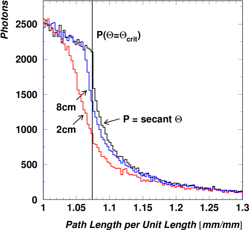
Figure 4 shows the distribution of the normalised path length, , for trapped photons reaching the exit end of straight fibres of 0.6 mm radius. The figure also gives results for curved fibres of two different radii of curvature. The distribution of path lengths which are shorter than the path length for meridional photons propagating at the critical angle is almost flat. It can be shown that the normalised path length along a straight fibre is given by the secant of the axial angle and is independent of other fibre dimensions: . It is clearly seen that, when a fibre is curved, the normalised path length of the trapped photons is less than the secant of the axial angle and photons on near meridional paths are refracted out of the fibre most. The average normalised path length for those photons which remain trapped is smaller than the average for the straight fibre. The over-all fibre length for the curved fibres in these calculations is 0.5 m and the fibres are curved over a circular arc for their entire length.
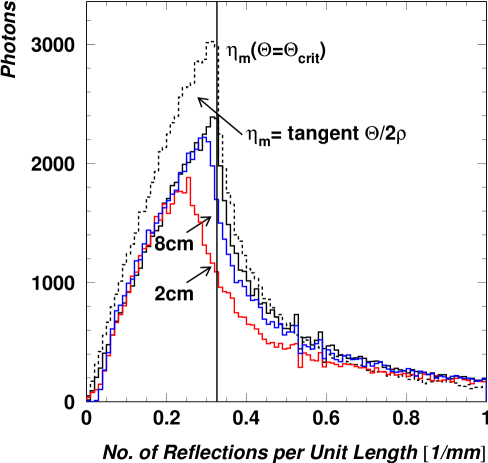
The distribution of the normalised number of reflections, , for photons reaching the exit end of straight and curved fibres is shown in figure 5. Again, the figure gives results for curved fibres of two different radii of curvature. The number of reflections a photon experiences scales with the reciprocal of the fibre radius. In the meridional approximation the normalised number of reflections is related by simple trigonometry to the axial angle and the fibre radius: . The distribution of , based on the distribution of axial angles for the trapped photons, is represented by the dashed line. The upper limit, , is indicated in the plot by a vertical line. The number of reflections made by a skew ray, , can be calculated for a given skew angle: . It is clear that this number increases significantly if the skew angle increases. From the distributions it can be seen that in curved fibres the trapped photons experience fewer reflections on average.
Internal reflections being less than total give rise to so-called leaky or non-guided modes, where part of the electromagnetic energy is radiated away. Rays in these modes populate a region defined by axial angles above the critical angle and skew angles slightly larger than the ones for totally internally reflected photons. In the simulation these modes are taken into account by using the Fresnel equation for the reflection coefficient, , averaged over the parallel and orthogonal plane of polarisation
| (12) |
where is the angle of incidence and is the refraction angle. However, it is obvious that non-guided modes are lost quickly in a small fibre. This is best seen in the fraction of non-guided to guided modes, , which decreases from at the first reflection of the ray over at the second reflection to at further reflections. Since the average reflection length of non-guided modes is mm those modes do not contribute to the flux transmitted by fibres longer than a few centimetres.
In the meridional approximation and substituting by the attenuation length can be written as
| (13) |
Only for small diameter fibres (mm) the attenuation due to imperfect reflections is of the same order as the absorption lengths. In calorimeters the reflection losses are not relevant for the transmission function, because of the large radii of the fibres used. There, the attenuation length contracts to . The transmission function including all skew ray effects can be found by integrating over the normalised path length distribution
| (14) |
where represents the number of photons per path length interval , weighted by the exponential bulk attenuation length. Figure 6 shows the simulated transmission function versus the ratio of fibre to absorption length, . A simple exponential fit, , applied to the simulated light transmissions for a large number of fibre lengths results in an effective attenuation length of . For this number is sufficiently accurate to parameterise the transmission function, at smaller values for the light is attenuated faster. The difference to the meridional attenuation length, , is attributed to the skew rays in the tail of the path length distribution.
Measurements of the light attenuation in fibres proved the simple model of a single effective attenuation length to be wrong. A dependence of the attenuation length with distance is usually observed [40]. One cause of this effect is the fact that the short wavelength components of the scintillation light is dominantly absorbed. The use of a double spectrometer allows the precise determination of the spectral attenuation length of fibres [41]. The characteristic shape of plastic spectral attenuation lengths shows a minimum at around 440 nm and an increase towards longer wavelengths. This leads to a shift of the average wavelength in the emission spectrum towards longer wavelengths and to an increase in the effective attenuation length. The wavelength dependent quantum efficiency of any photon sensor enhances this effect, so that the integral attenuation length is only a rough quality criterion for the light yield of a fibre.
D Transmission of Sharply Curved Fibres
One of the most relevant practical issues in implementing optical fibres into compact particle detector systems are macro-bending losses. In general, some design parameters of fibre applications, especially if the over-all size of the detector system is important, depend crucially on the minimum permissible radius of curvature. The problem of bending is eminent for tile-fibre calorimeters where wavelength-shifting fibres are embedded in plastic scintillator tiles and are bent at radii of curvature of a few centimetres. Flexibility of the fibres is also essential for space physics experiments or for detectors carried by balloons or aircrafts. The routing of fibres to photon sensors requires radii of curvature as small as possible to minimise the weight and the costs associated with the transport of the detector, see e.g. [42].
Photons are lost from a fibre core both by refraction and tunnelling. In the simulation only refracting photons were considered. The angle of incidence of a light ray at the tensile (outer) side of the fibre is always smaller than at the compressed side and photons propagate either by reflections on both sides or in the extreme meridional case by reflections on the tensile side only. If the fibre is curved over an arc of constant radius of curvature, photons can be refracted, and will then no longer stay trapped, at the very first reflection point on tensile side. Therefore, the trapping efficiency for photons entering a curved section of fibre towards the tensile side is reduced most.
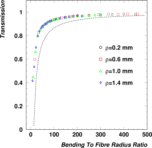
Figure 7 displays the explicit dependence of the transmission function for fibres curved over circular arcs of 90∘ on the radius of curvature to fibre radius ratio for different fibre radii, 0.2, 0.6, 1.0 and 1.2 mm. No further light attenuation is assumed. Evidently, the number of photons which are refracted out of a sharply curved fibre increases very rapidly with decreasing radius of curvature. The losses are dependent only on the curvature to fibre radius ratio, since no inherent length scale is involved, justifying the introduction of this scaling variable. The light loss due to bending of the fibre is about 10% for a radius of curvature of 65 times the fibre radius.
The transmission function in the meridional approximation in the bending plane can be estimated by assuming that all photons with axial angles above a limiting angle, ), are refracted out of the fibre:
| (15) |
This transmission function is shown in figure 7 as a dashed line to be compared with the simulation results including all skew rays. It overestimates the light losses due to the larger axial angles allowed for skew rays. The meridional approximation in the bending plane is, however, a good approximation for the transmission function because the light losses are dominantly produced by meridional rays [15, 43].
A comparable theoretical calculation using a two-dimensional slab model and a generalised Fresnel transmission coefficient has been performed by Badar and co-workers [44]. Their plot of the power contained in the fibre core as a function of the radius of curvature (figure 5 in [44]) shows results on the transmission function in the meridional approximation which are similar to the simulation output. In [15] a ray optics calculation for curved multimode fibres involving skew rays is presented, unfortunately a discussion on the transmission function is missing. Instead, a plot of the power remaining in a curved fibre versus distance is shown which gives complementary information.
For photons entering a curved section of fibre the first point of reflection on the tensile side defines the transition angle, , measured from the plane of entry. Figure 9 shows a section of a curved fibre and the passage of a meridional ray in the bending plane with maximum axial angle. The angular range of transition angles associated with each ray is called the transition region of the fibre. The simulation results on the transmission as a function of bending angle, , for a “standard” fibre are presented in figure 8. Once a sharply curved fibre with a ratio is bent through angles rad, light losses do not increase any further. For ratios smaller than 10 the model is no longer valid to describe the transmission function.
For photons emitted towards the tensile side the transition angle is related to the axial angle. Since the angular phase space density of trapped photons is highest close to the critical angle the difference allows to estimate the transition angle. Photons emitted from the fibre axis towards the compressed side are not lost at reflections on this side. They experience at least one reflection on the tensile side if the bending angle exceeds the limit . Therefore, a transition in the transmission function should occur at bending angles between , where photons emitted towards the tensile side must have experienced a reflection, and , where this is true for all photons. For a fibre radius 0.6 mm and radii of curvature 1, 2 and 5 cm the above formula leads to transition regions rad which are indicated in figure 8 by arrows.
Transition and bending losses have been thoroughly investigated using waveguide analysis techniques from which a loss formula in terms of the Poynting vector has been derived [45, 46]. Those studies are difficult to extend to multimode fibres since a large number of guided modes has to be considered. Despite the extensive coverage of theory and experiment in this field, only fragmentary studies on the trapping efficiencies and refraction of skew rays in curved multimode fibres could be found [15, 44, 47, 48]. When applying ray optics to curved multimode fibres the use of a two-dimensional model is very common [44, 47, 48]. In contrast, the simulation method presented in this paper follows a three-dimensional approach.
Experimental results on losses in curved multimode fibres along with corresponding predictions are best known for silica fibres with core radii m. Results on multimode plastic fibres are rare. The manufacturer Kuraray has investigated a time dependent drop of the transmission of curved plastic fibres on time scales of several days [49]. A dependence of the bending losses on the parameter was found. This parameter is a characteristic index for the degree of orientation of polystyrene chains along the fibre axis, where fibres are more flexible for larger values. Consequently, softer and more flexible fibres have been developed by Kuraray (so-called type fibres). Bending losses of more than 50% in 1 mm diameter Bicron BCF-91A fibres have been observed for one turn of 360∘ with a radius of curvature of 5 cm [50]. With the same type of fibres no effect was seen for a radius of 10 cm. Calculations on the basis of ray optics for a plastic fibre with mm can be found in [48]. The simulation result on the transmission function in the meridional approximation at is in good agreement with this two-dimensional calculation. The higher transmission of for this curvature as predicted by the simulation is explained by the fact that skew rays are less sensitive to bending effects. It should be noted that the difference between finite and infinite cladding and oscillatory losses in the transition region have not been investigated in the simulation.
E Transmission of Irradiated Fibres
It is frequently desirable to have fibre detectors very close to beams and targets. This task results in rather demanding specifications. The fibres have to reasonably immune to radiation or any other effect of aging within the expected period of operation.
Radiation resistance remains to be an important issue for detectors at high luminosity accelerators. It is influenced by many parameters: dose rate, recovery times, temperature, chemical composition, level of dissolved oxygen and others. Since the effective attenuation length is essentially the only property which is affected by the irradiation, the transmission curves before and after exposure to electromagnetic radiation can be used to study the influence of the deposited energy dose on the light yield. Many data points for various irradiation conditions exist. From these experiences one can draw the following, simplified conclusions for most modern fibres: after irradiation the attenuation length is reduced significantly compared to the original value, while the scintillation mechanisms themselves are not strongly affected. Parts of the attenuation length recover on multiple time scales. The manufacturer Kuraray gives a simple formula for estimating the ratio of attenuation lengths after to before the irradiation as a function of the absorbed dose, (for ), in units of krad (1 krad 10 Gy) [49]:
| (16) |
In general, strong dose rate effects are observed and a more accurate description has to include the dynamics of absorption centres. Three types of absorption centres can be formed during irradiation: (1) stable absorption centres leading to a permanent damage, (2) radicals (e.g. benzyl radicals of polystyrene) which decay practically at once if oxygen is dissolved in the fibre, and (3) short-lived absorption centres which decay within hours via bi-molecular reactions [51]. The short-lived absorption centres in polystyrene mainly absorb red and green light and it was concluded that these centres are caused by the dopants and not the base material.
For the quantitative analysis of the radiation induced changes the difference in the absorption coefficients of the irradiated and non-irradiated fibre, , is usually quoted, where is the wavelength and is the inverse light attenuation length. For many fibres the permanent induced absorption, , that is the damage after the end of the recovery process, rises linearly with the absorbed dose for moderate doses between 0.1 and 6 kGy [51]. For larger absorbed doses becomes a non-linear function. The annealable part of the absorption, , shows a broad maximum in the blue spectral region of many irradiated fibres.
V Timing Properties
The timing properties of active fibres are usually defined in terms of a coincidence timing resolution between identical counters. For small counters a timing resolution in the range of ps can be achieved. Several effects which are dependent on the signal amplitude, , contribute to the timing resolution, namely the scintillation process with its decay time , the photomultiplier tube with its transit time spread and the fibre as a light guide with its pulse dispersion . The discriminator, which could be either of type leading edge or constant fraction, and any noise in the electronic circuits contribute to the timing distribution. They may shift the response time with signal amplitude (“time walk”). Time walk effects can get corrected by various means, either in hardware or software [52]. Usually, the remaining effect is parameterised by the time spread . A common way of summarising the different contributions to the timing resolution is the following:
| (17) |
where the factor assumes two identical counters for start and stop time, whose timing resolutions add up quadratically: .
A Statistical Fluctuations
Obviously, the signal amplitude depends on the number of photoelectrons, , appearing during some integration time, . This number fluctuates from one pulse to another. The mean number of photoelectrons per pulse, , and its variance, , are characteristic of the photoelectron statistics. As the number of photoelectrons increases, a larger number of time intervals is sampled. For a precise quantitative description of the distribution of one has to use quantum theory, where the number of photoelectrons becomes an operator. However, in a semiclassical model the probability for observing photoelectrons over a time interval is given by a Poissonian distribution . For larger numbers of photoelectrons the distribution is assumed to be Gaussian, so that the signal amplitude dependent contributions should vary with .
In active fibres the addition of fluorescent dopants can sharply reduce the decay times of some scintillating base materials by Förster transitions, which couple base and fluorescent dye in extremely short times. The base material polyvinyltoluene can be quenched with benzophenone, for example, to reach a 220 ps pulse width. The faster timing comes at the expense of light yield, however. For most plastic fibres the short time behaviour can be described phenomenologically by a single decay constant, , usually of the order of a few nanoseconds. The decay times in wavelength-shifting fibres are substantially longer than the scintillator decay constants. Typical wavelength-shifting molecules have decay times of ns, dominating the time characteristics of the entire detector. For critical timing situations wavelength-shifting fibres are usually avoided.
The contribution of the photomultiplier tube to the time width of the observed output pulse is determined exclusively by the electron transit time spread, , where the transit time is the time difference between photoemission at the cathode and the arrival of the subsequent electric signal at the anode. Modern compact photomultiplier tubes like the Hamamatsu R-5900 reach transit time spreads of ps with anode pulse rise times of ps for single photoelectrons. The timing performance of photomultiplier tubes is an active area of development and it is assumed that even faster tubes will be available. In many cases, the transit time spread of conventional 1 inch photomultiplier tubes is well described by a dependence. Sometimes, other dependences of on are seen. Ref. [53] gives an example of a dependence for a specific photomultiplier tube.
B Light Pulse Dispersion
A pulse of light, consisting of several photons propagating along a light guide, broadens in time. The chromatic dispersion is due to the spectral width, , of the emission band. It is a combination of material dispersion and waveguide dispersion. If the core refractive index is explicitly dependent on the wavelength, , photons of different wavelengths have different propagation velocities along the same path, called material dispersion. The broadening of a pulse travelling along a fibre is given by , where is the spectral width of the emission peaks of scintillating or wavelength-shifting fibres [19]. The full widths at half maximum (FWHM) of the emission bands in most fibre polymers (e.g. polystyrene) is approximately nm and the material dispersion is of the order of a few nsnm per kilometre fibre length and is almost negligible for multimode fibres.
Because of the linear dependence of the transit time on the path length the transit time is simply given by , where is the speed of light in the fibre core and is the total axial length of the fibre. The simulation results on the transit time are shown in figure 10. The FWHM of the pulses in the time spectrum are presented for four different fibre lengths. The resulting dispersion has to be compared with the time dispersion in the meridional approximation which is simply the difference between the shortest transit time and the longest transit time : . The dispersion evaluates for “standard” fibres to 197 ps for 0.5 m, 393 ps for 1 m, 787 ps for 2 m and 1181 ps for 3 m. Those numbers are in good agreement with the simulation, although there are tails associated to the propagation of skew rays. Using average attenuation parameters as discussed in section 4 the fraction of photons arriving later than decreases from 37.9% for a 0.5 m fibre to 32% for a 3 m fibre due to the stronger attenuation of the skew rays in the tail. Because of the inter-modal dispersion the pulse broadening in multimode fibres is quite significant and for longer fibres ( 1 m) the light dispersion due to path length variations, , dominates the timing resolution.
In the meridional approximation and assuming an isotropic emission, , the probability of a photoelectron to get emitted before a time can be derived. The normalised transit time distribution in this approximation is , leading to the probability
| (18) |
Then, the average transit times and can be calculated, resulting in a time dispersion due to path length differences:
| (19) |
Recalling that and will reproduce the linear dependence of the time dispersion on the distance between the emission point and the photon sensor measured along the fibre axis.
In order to reduce noise from dark counts the threshold of a discriminator used with a time-to-digital converter is usually larger than the minimum voltage corresponding to one photoelectron. Assuming that the time measurement requires a fixed number of photoelectrons, , and photoelectrons are produced in a given event, then simple probabilistic considerations provide the time distribution of photoelectron :
| (20) |
Calculating the time dispersion in the same way as for the single photoelectron case involves Gauss’s hyper geometric function, , which arises frequently in physical problems,
| (21) |
where is Euler’s Gamma function. Obviously, the integral is dependent on , and so the statistical behaviour of the timing resolution is a function of the threshold. A parameterisation of the integral with is common. For a large number of photoelectrons the approximation is better suited.
The maximum axial angle allowed by the critical angle condition is smaller in fibres than in bulk scintillators by
| (22) |
which equals for “standard” fibres. Thus, the time dispersion due to path length variation is significantly reduced in fibre bundles. A pioneering work by Kuhlen and co-workers [38] has shown that the timing resolution achieved with a scintillating fibre detector is about a factor two better than the timing resolution achieved with a geometrically identical bulk scintillator.
VI Conclusions
Since the first demonstration of a scintillating fibre detector in the early 1980s, particle detection and read-out techniques using active fibres have become mainstream. Developments were mainly based on step-index fibres with polystyrene cores. The plastic scintillators in active fibres are composites of more than one type of fluorescent molecules containing aromatic rings. The energy transfer mechanisms in these binary or even tertiary mixtures are complex, involving radiationless internal conversions and overlapping absorption and emission bands.
Nowadays, active optical fibres are an integral part of hadron calorimetry. In addition, tracking detectors comprising thousands of scintillating fibres are frequently built into large detector systems. Wavelength-shifting fibres are found in several modern particle physics experiments around the world. They allow for a read-out with a very high level of hermeticity. Recently, the ongoing interest concentrated on the development of low-mass particle detectors with high timing and spatial resolutions.
Because of the relatively low quantum efficiency of the scintillator and the low trapping efficiencies in fibres, the light yield at the end of a long fibre is typically small. Thus, a detailed understanding of the photon propagation characteristics is almost inevitable. In this paper, the propagation of photons in straight and curved optical fibres has been reviewed. The geometrical conditions have been illustrated to explain the quantitative difference between meridional and skew rays. The overall transmission through a fibre cannot be described by a simple exponential function of propagation distance. One contribution to this effect is the large spread in optical path lengths between the most meridional and most skew rays.
Since light pulses are often near the noise level of the measurement system, the light yield can get critically low for sharply curved fibres, e.g. as used in calorimeters with a large hermeticity. A Monte Carlo programme has been used to evaluate the loss of photons propagating in fibres curved in a circular path in one plane. The results show that the loss of photons due to the curvature of the fibre is a simple function of radius of curvature to fibre radius ratio and the transmission is if the ratio is . The simulations also show that for larger ratios this loss takes place in a transition region during which a new distribution of photon angles is established. Photons which survive the transition region propagate without further losses.
It is long known that long fibres have better timing resolutions than bulk scintillation counters of the same overall dimensions. Fast photon sensors with transit time spreads ns in conjunction with plastic scintillators with time constants ns allow the measurement of time differences on the level of ps. Several effects are responsible for the signal time spread in active fibres. There are variations in the response time of the scintillator, which include time variations in the energy transfer and the finite decay time of the fluorescent dyes. Effects due to the light detection include variations in the transit time from the photocathode to the first dynode of photomultiplier tubes. Another group of limitations is due to the electronics circuits used to process the signal. One of the main contributions to the finite timing resolution comes from the time dispersion due to path length variation in the fibre. The simulation has been used to investigate the dispersion of transit times of photons propagating in straight fibres. For fibre lengths between 0.5 and 3 m approximately two thirds of the photons arrive within the spread of transit times which would be expected from the use of the simple meridional approximation and the refractive index of a “standard” fibre core. The remainder of the photons arrive in a tail at later times due to their helical paths in the fibre. The fraction of photons in the tail of the distribution decreases only slowly with increasing fibre length and will depend on the attenuation parameters of the fibre.
In conclusion, the timing properties of today’s commercially available fibres and photomultiplier tubes allow resolutions in the sub-nanosecond region and the small detector dimensions make them very attractive for experiments at present and future high luminosity accelerators.
ACKNOWLEDGMENTS
I wish to express my thanks to J.H. Cobb who initiated my works on optical fibres during my years at Oxford University.
REFERENCES
- [1] R. Mussa, M. Onorato, N. Pastrone, D. Bettoni, R. Calabrese, B. Camanzi, and E. Luppi, “Development of a cylindrical scintillating fiber tracker for experiment E835 at FNAL,” Nucl. Instr. and Meth. in Phys. Res. A360, 13–16 (1995).
- [2] P. Annis et al., “The CHORUS scintillating fiber tracker and opto-electronic readout system,” Nucl. Instr. and Meth. in Phys. Res. A412, 19–37 (1998).
- [3] A. Suzuki et al., “Design, construction, and operation of SciFi tracking detector for K2K experiment,” Nucl. Instr. and Meth. in Phys. Res. A453, 165–176 (2000).
- [4] ATLAS Collaboration, “A general purpose experiment at the LHC,” Technical proposal, CERN/LHCC/94-43, CERN (1994) .
- [5] S. Horikawa et al., “Time resolution of a scintillating fiber detector,” Nucl. Instr. and Meth. in Phys. Res. A431, 177–184 (1999).
- [6] S. Sedykh et al., “Electromagnetic calorimeters for the BNL muon (g-2) experiment,” Nucl. Instr. and Meth. in Phys. Res. A455, 346–360 (2000).
- [7] A. Antonelli et al., “Measurements of light yield, attenuation length and time response of long samples of ”blue” scintillating fibers,” Nucl. Instr. and Meth. in Phys. Res. A370, 367–371 (1996).
- [8] MINOS Collaboration, “The MINOS Detectors,” Technical Design Report, NuMI-L-337, Fermilab (1998) .
- [9] LHCb Collaboration, “A large hadron collider beauty experiment for precision measurements of CP violation and rare decays,” Technical proposal, CERN/LHCC/98-04, CERN (1998) .
- [10] CMS Collaboration, “The Hadron Calorimeter,” Technical Design Report, CERN/LHCC 97-31, CERN (1997) .
- [11] Y. Giomataris, P. Rebourgeard, J. P. Robert, and G. Charpak, “MICROMEGAS: a high-granularity position-sensitive gaseous detector for high particle-flux environments,” Nucl. Instr. and Meth. in Phys. Res. A376, 29–35 (1996).
- [12] F. Sauli, “GEM: a new concept for electron amplification in gas detectors,” Nucl. Instr. and Meth. in Phys. Res. A386, 531–534 (1997).
- [13] E. Snitzer, “Cylindrical dielectric waveguide modes,” J. Opt. Soc. Am. 51, 491–498 (1961).
- [14] N. S. Kapany, J. J. Burke, and C. C. Shaw, “Fiber Optics. X. Evanescent Boundary Wave Propagation,” J. Opt. Soc. Am. 53, 929–935 (1963).
- [15] C. Winkler, J. D. Love, and A. K. Ghatak, “Loss calculation in bent multimode optical waveguides,” Opt. Quantum Electron. 11, 173–183 (1979).
- [16] N. S. Kapany, “Fiber Optics. I. Optical properties of certain dielectric cylinders,” J. Opt. Soc. Am. 47, 413–422 (1957).
- [17] N. S. Kapany, Fibre optics: principles and applications (Academic Press, London and New York, 1967).
- [18] W. B. Allan, Fibre optics: theory and practice, Optical Physics and Engineering (Plenum Press, London and New York, 1973).
- [19] A. Ghatak and K. Thyagarajan, Introduction to fiber optics (Cambridge University Press, Cambridge, 1998).
- [20] T. O. White, “Scintillating fibres,” Nucl. Instr. and Meth. in Phys. Res. A273, 820–825 (1988).
- [21] H. Leutz, “Scintillating Fibres,” Nucl. Instr. and Meth. in Phys. Res. A364, 422–448 (1995).
- [22] J. B. Birks, The theory and practice of scintillation counting (Pergamon Press, Oxford, 1964).
- [23] K. Kuroda, D. Sillou, and F. Takeutchi, “New type of position sensitive photomultiplier,” Rev. Sci. Instrum. 52, 337–346 (1981).
- [24] FAROS Collaboration, “Fast readout of scintillating fiber arrays using position-sensitive photomultipliers,” Nucl. Instr. and Meth. in Phys. Res. A357, 78–86 (1995).
- [25] FAROS Collaboration, “Scintillating fiber hodoscopes using position-sensitive photomultipliers,” Nucl. Instr. and Meth. in Phys. Res. A372, 63–69 (1996).
- [26] V. Agoritsas et al., “Read-out of scintillating fibres using a weak cross-talk position-sensitive photomultiplier,” Nucl. Instr. and Meth. in Phys. Res. A406, 393–402 (1998).
- [27] Photomultiplier Tubes and Assemblies For Scintillation Counting & High Energy Physics, Hamamatsu Photonics, Hertfordshire, United Kingdom, 2000, (catalog TPMO0001E06).
- [28] Y. Yoshizawa and J. Takeuchi, “The latest vacuum photodetector,” Nucl. Instr. and Meth. in Phys. Res. A387, 33–37 (1997).
- [29] M. Enkelmann, U. Werthenbach, G. Zech, and T. Zeuner, “An optical readout for a fiber tracker,” Nucl. Instr. and Meth. in Phys. Res. A412, 216–222 (1998).
- [30] M. Ambrogiani, W. Baldini, D. Bettoni, R. Calabrese, E. Luppi, R. Mussa, and G. Stancari, “Results from the E835 scintillating fiber detector,” Nucl. Instr. and Meth. in Phys. Res. A419, 632–636 (1998).
- [31] J. Bähr, H. Bärwolff, V. Kantserov, G. Kell, and R. Nahnhauer, “Investigation of silicon avalanche photodiodes for use in scintillating fiber trackers,” Nucl. Instr. and Meth. in Phys. Res. A442, 203–208 (2000), 2nd Conference on New Developments in Photodetection, Beaune, France, June 21–25, 1999.
- [32] C. P. Achenbach and J. H. Cobb, “Computational studies of light acceptance and propagation in straight and curved multimodal fibres,” J. Opt. A: Pure Appl. Opt. 5, 239–249 (2003).
- [33] W. H. Press, S. A. Teukolsky, W. T. Vetterling, and B. P. Flannery, Numerical recipes in Fortran77: the art of scientific computing, 2nd ed. (Cambridge University Press, Cambridge, 1992), Vol. 1 of Fortran Numerical Recipes.
- [34] R. J. Potter, “Transmission properties of optical fibers,” J. Opt. Soc. Am. 51, 1079–1089 (1961).
- [35] N. S. Kapany and D. F. Capellaro, “Fiber Optics. VII. Image Transfer from Lambertian Emitters,” J. Opt. Soc. Am. 51, 23–31 (1961), (appendix: Geometrical optics of straight circular dielectric cylinder).
- [36] R. J. Potter, E. Donath, and R. Tynan, “Light-collecting properties of a perfect circular optical fiber,” J. Opt. Soc. Am. 53, 256–260 (1963).
- [37] K. F. Johnson, “Achieving the theoretical maximum light yield in scintillating fibres through non-uniform doping,” Nucl. Instr. and Meth. in Phys. Res. A344, 432–434 (1994).
- [38] M. Kuhlen, M. Moszynski, R. Stroynowski, E. Wicklund, and B. Milliken, “Timing properties of long scintillation counters based on scintillating fibers,” Nucl. Instr. and Meth. in Phys. Res. A301, 223–229 (1991).
- [39] C. D’Ambrosio, H. Leutz, and M. Taufer, “Reflection losses in polysterene fibres,” Nucl. Instr. and Meth. in Phys. Res. A306, 549–556 (1991).
- [40] A. J. Davis, P. Hink, W. Binns, J. Epstein, J. Connell, M. Israel, J. Klarmann, V. Vylet, D. Kaplan, and S. Reucroft, “Scintillating optical fiber trajectory detectors,” Nucl. Instr. and Meth. in Phys. Res. A276, 347–358 (1989).
- [41] G. Drexlin, V. Eberhard, D. Hunkel, and B. Zeitnitz, “Spectral attenuation length of scintillating fibres,” Nucl. Instr. and Meth. in Phys. Res. A360, 245–247 (1995).
- [42] C. P. Achenbach and J. H. Cobb, “A new airborne detector for atmospheric muons,” In Proc. of the 27th Int. Cosmic Ray Conf. (ICRC 2001), K.-H. Kampert, G. Hainzelmann, and C. Spiering, eds., pp. 1313–1316 (Copernicus Gesellschaft, Katlenburg-Lindau, 2001).
- [43] D. Gloge, “Bending loss in multimode fibers with graded and ungraded core index,” Appl. Opt. 11, 2506–2513 (1972).
- [44] A. H. Badar, T. S. M. Maclean, H. Ghafoori-Shiraz, and B. K. Gazey, “Bent slab ray theory for power distribution in core and cladding of bent multimode optical fibres,” IEE Proc. J 138, 7–12 (1991).
- [45] D. Marcuse, “Curvature loss formula for optical fibers,” J. Opt. Soc. Am. 66, 216–220 (1976).
- [46] W. A. Gambling, H. Matsumura, and C. M. Ragdale, “Curvature and microbending losses in single-mode optical fibres,” Opt. Quantum Electron. 11, 43–59 (1979).
- [47] A. H. Badar, T. S. M. Maclean, B. K. Gazey, J. F. Miller, and H. Ghafoori-Shiraz, “Radiation from circular bends in multimode and single-mode optical fibres,” IEE Proc. J 136, 147–151 (1989).
- [48] A. H. Badar and T. S. M. Maclean, “Transition and pure bending losses in multimode and single-mode bent optical fibres,” IEE Proc. J 138, 261–268 (1991).
- [49] K. Hara, K. Hata, S. Kim, M. Mishina, M. Sano, Y. Seiya, K. Takikawa, M. Tanaka, and K. Yasuoka, “Radiation hardness and mechanical durability of Kuraray optical fibers,” Nucl. Instr. and Meth. in Phys. Res. A411, 31–40 (1998).
- [50] A. Gomes, M. David, A. Henriques, and A. Maio, “Comperative study of WLS fibres for the ATLAS tile calorimeter,” Nucl. Phys. B (Proc. Suppl.) 61, 106–111 (1998).
- [51] K. Wick and T. Zoufal, “Unexpected behaviour of polystyrene-based scintillating fibers during irradiation at low doses and low dose rates,” Nucl. Instr. and Meth. in Phys. Res. B185, 341–345 (2001).
- [52] H. Spieler, “Fast timing methods for semiconductor detectors,” IEEE Trans. Nucl. Sci. NS-29, 1142–1157 (1982).
- [53] H. Kume, S. Muramatsu, and M. Iida, “Position sensitive photomultiplier tubes for scintillation imaging,” IEEE Trans. Nucl. Sci. NS-33, 359–363 (1986).
‘