Integration and Conventional Systems at STAR
Abstract
At the beginning of the design and construction of the STAR Detector, the collaboration assigned a team of physicists and engineers the responsibility of coordinating the construction of the detector. This group managed the general space assignments for each sub-system and coordinated the assembly and planning for the detector. Furthermore, as this group was the only STAR group with the responsibility of looking at the system as a whole, the collaboration assigned it several tasks that spanned the different sub-detectors. These items included grounding, rack layout, cable distribution, electrical, power and water, and safety systems. This paper describes these systems and their performance.
, , , , , , and
1 Introduction
The STAR collaboration has built a detector to study Nucleus-Nucleus collisions at the Relativistic Heavy Ion Collider (RHIC) which is located at Brookhaven National Laboratory. The detector started taking data in the year 2000 and has already published[1, 2] several papers. To achieve this, many years of planning and design were needed.
When the project began, a group of physicists and engineers were given the responsibility to coordinate the activities from the many sub-systems. This group worked with the other STAR groups so that a coherently planned detector was constructed. Each individual sub-system focused on the optimum performance of its design. However, this group, which had a global or overall system level perspective, assured that the individual plans worked well together.
As the sub-systems had several items in common, it was prudent for one group to undertake the design of these common elements. For instance, the cooling and powering of each electronic rack is essentially the same for each sub-system. Similarly, as the over all cable plan is common to each sub-system, it is more efficient to build only one set of cable trays. The integration and conventional systems group was assigned these tasks in addition to defining the boundaries and interfaces between each sub-system. What follows is a description of this group’s activities.
2 Overall Layout of STAR
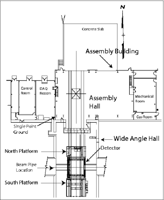
When the accelerator was under construction, RHIC management assigned the STAR detector[3] to the Wide Angle Hall (WAH), located at the 6 o’clock position in the accelerator ring. A diagram of the full STAR facility can be found in Fig. 1. As the WAH was built for the previous accelerator, Isabelle, much of our design was constrained by this existing structure. A large addition, which is called the Assembly Building, was needed to accommodate the assembly of the detector and to house the magnet power supplies and the water and gas system. The largest room in the Assembly Building, called the Assembly Hall (AH), was used to assemble the detector. In this room, the magnet and platforms were constructed. In a separate area, the TPC was tested and then inserted into the magnet. The detector easily moves between the AH and WAH over two metal rails.
At the center of the WAH, RHIC beams collide in a vacuum beam pipe, which is located 4.31 m above the floor. The STAR detector surrounds this beam pipe and provides the data to analyze the collisions. A platform is on each side of the detector. These structures provide a location for the detector electronics, pumps, power supplies, and detector utilities, such as water, power, and gas. The South Platform, which is south of the detector, contains most of the detector electronics while the North Platform holds the magnet controls and power transformers. It is also a support for the magnet and AC power leads. The North and South Platforms and the Detector move as one unit. Only a few utility connections such as power, water and gas need to be disconnected before the detector can travel between the WAH and AH.
As any item in the WAH can not be readily accessed when the accelerator operates, we minimized the equipment that resides there. Nearly all equipment that must be adjacent to the detector can be operated remotely. The electronics in the Data Acquisition Room (DAQ) receive trigger and digital data and also communicate with the detector through an optical Ethernet link. This room is shielded from the accelerator beam by concrete so that it can be accessed during operation of the beam. Adjacent to this room is the Control Room where physicists monitor the data from the detector.
Next to the Assembly Hall is a two-story structure, which houses the magnet power supply, gas and water systems. The Assembly Hall is used when the detector needs extensive servicing and provides a facility for testing sub-systems.
3 Integration Drawings
The STAR detector has many layers. As these layers were constructed at different institutions, it was necessary to coordinate the design of each element. Therefore, when such a complex detector is being built, it is necessary to define guidelines so that these detectors can come together cohesively. As the final dimensions of each sub-system are not known at the start of the project, we defined what was called an “envelope”.
Each sub-system is assigned several dimensions in a series of drawings.[4] It is the responsibility of each sub-system manager to assure that his/her sub-system fits completely inside the envelope. To ensure that there are no interferences between sub-systems, space is reserved for utilities, signal cables, support structures and so forth. Often a small “management reserve” is inserted to account for future growth and changes. This reserve could be as small as 1 to 2 cm. These integration drawings provided the guidelines so that the whole detector would come together properly.
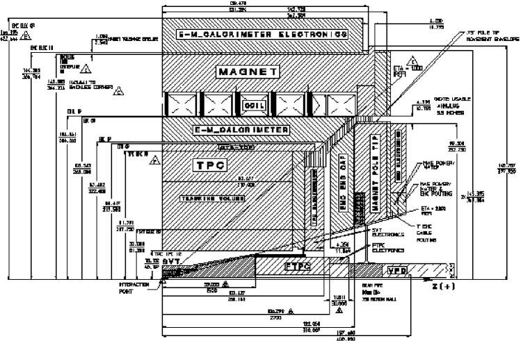
Figure 2 depicts a quarter section of the detector. This drawing shows the cylindrical radius and z value of the major components in the detector. This figure is just one of the many series of drawings needed to define the dimensions of the detector. To assure that there was space for the future additions, these subsystems were included in the envelope drawings.
4 Safety – Interlocks
An interlock system has been designed[8] and implemented to protect the STAR detector from damage. The STAR Interlock system consists of the interlocks for specific STAR sub-systems as well as a global system, which supervises those systems. All of these interlocks utilize Allen-Bradley[10] Programmable Logic systems.
The inputs to this system include flammable gas detectors, smoke detectors, water leak detectors, and the status of some of the facility systems necessary to operate the detector (e.g. water cooling systems). The actions that the interlock system can take automatically include such things as removing AC power from either selected items or the entire detector. It can also change the STAR flammable gas systems to purge modes with nonflammable gases. Upon sensing a water leak, it can turn off water flow from portions of the detector, remove the High Voltages for the electronics, and ramp down the STAR magnet.
Whenever a fault is detected by the global interlock system, it automatically puts the detector in a safe state. Simultaneously, the system sends alarms both locally in the STAR complex as well as at the RHIC main control room.
There are different levels of response depending on the error condition. For some conditions, the interlock system provides a warning, leaving time for human corrective action. If the condition is not corrected after a defined time, then automated correction is invoked. For other conditions the interlock takes corrective measures immediately. Except for the relatively rare occasions when the entire STAR detector is being physically moved or when the interlock system is being modified, the system is always in operation.
5 Grounding
It is the common experience of experiments to find that the detector in an experiment has significantly more electrical noise then was measured in the laboratory. A frequent culprit to noise problems is poorly planned electrical distribution. There may be many different and ill-defined electrical paths, resulting in current loops, which in turn produce spurious electrical signals.
To reduce electrical noise pickup requires a single point ground and a well-planned distribution of electrical power.[5, 6] Care must be taken to avoid coupling from noisy electrical devices such as motors, pumps and switching power supplies. As only the physical building existed before the STAR detector was constructed, we were able to design an electrical system with few prior constraints.
While it is possible to make sure that the detector has a DC resistance greater than 100 M from any sources other than the single point ground, it is very difficult to completely eliminate the capacitive coupling. Therefore, we had to make an electrical model of the STAR detector. To gauge how much capacitance would be acceptable, we examined the effect of it on the most sensitive element of the base line STAR detector – the TPC digitizing electronics. For instance, the capacitance of a TPC pad is 30 pf with about 1000 electron RMS noise. It was necessary to control the STAR electrical environment so that this noise was not increased significantly on the TPC pads.
We devised a grounding plan[7] that separated the electrical components from each other, reduced stray capacitance, and split the electrical power distribution. The schematic for the plan is shown in Fig. 3. We mandated that the detector should use optical connections when possible, that the detector be electrically isolated in DC resistance, and that the capacitance between the detector and its surroundings be held to less than 5 nf. This value of capacitance was selected so that anticipated noise sources would not appreciatively affect the TPC front-end electronics up to 100 kHz.
A column in the Assembly Hall was selected at the earth contact of the experiment. A total of eight 4/0 cables ground the magnet to this column. These cables provide the single point ground to the detector. We selected this column because is about 30 m away from the beam pipe, and consequently beam induced electrical noise would be attenuated before it reached the column. It was also in a convenient place to ground the detector when it is either in the WAH or AH. It is also adjacent to the DAQ Room so that both the detector and its electronics have the same ground.
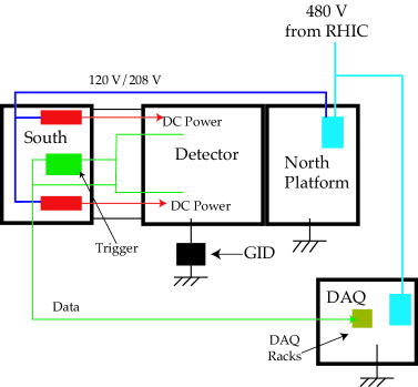
The trigger and power supplies to the detector reside on the South Platform. These items communicate with the DAQ room via optical cables. The North Platform, which is electrically isolated from the detector, holds items such as the 480V transformers and magnetic monitoring equipment. We ordered transformers with electrostatic shields so that electrical noise from the power grid did not enter our power distribution system.
6 Facility AC Power
The 6 o’clock facilities for the Detector have AC power feeds from two separate substations. The first substation is a 13.8 kVA feed that supplies 480 V transformer power to detector power panel A1 located in the DAQ room. This panel provides power distribution to detector electronics through three shunt trip breakers A11, A12, and A13. Shunt trip breakers are used as required to interlock all detector AC power with the STAR Global Interlocks System (SGIS).
Circuit A11 provides “Clean Power” to 480 V isolation transformer located on the North Platform. From these isolation transformer 208/120 V clean power is distributed to individual electronics racks on the South platform through rack row breaker panels. The second circuit, A12, supplies “Dirty Power” to 480 V transformer on the North Platform for 208/120 V power distribution. This power is used strictly on the North Platform to provide lighting and power for detector subsystem rotary equipment that will generate line noise. The last circuit, A13, provides DAQ and Control Room Power to a 480 V isolation transformer located in the DAQ room. From this isolation transformer 208/120 V clean power is distributed to DAQ electronics racks and to Control Room computer systems.
Shunt trip breakers interlocked to SGIS are assigned to those electronic racks that are temperature sensitive and require Modified Chilled Water (MCW) cooling and leak detection. On each rack, there are P2 rack breaker panels which distribute 208/120 V power to the electronics.
The second AC power feed comes from a 13.8 kVA overhead line to substation-8 located on the East Side of the Facility. This feed provides power to the facilities buildings for conventional systems use and also to power the STAR Magnet DC power supplies. There is a direct 13.8 kVA feed to the Main Magnet switch gear that in turn feeds the Main Magnet transformers and rectifier, which can provide a maximum of 5000 A @ 600 VDC. There is also a 480 V feed to the four other Magnet Trim transformers and rectifiers used to control magnetic field quality in the detector.
7 Rack Design
To preserve the life of the electronics, it is important to have the electronics operate close to room temperature. It is widely known that as the temperature of electronics increases, the reliability decreases. Because of the extremely limited space on the STAR platform, we had to pack the electronics as densely as possible. Since we did not want a situation where there was excessive heat build up inside the rack, we decided to put water-cooled heat exchangers in each crate.
Figure 4 shows a typical arrangement for a rack with VME crates. The heat exchangers are modeled after those designed[11] for the D0 experiment. The fans inside the 6U and 9U sections of the VME crate blow the air up. The fans in the back of the crate move the air down to facilitate the airflow. A filter held by a simple metal frame traps dust inside the rack. A P2 breaker panel, which distributes electrical power, is located on top of the rack.
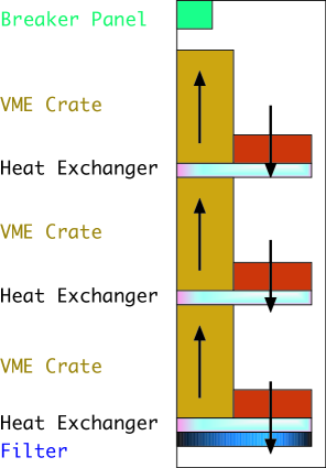
Racks are arranged so that two 19” racks occupy one volume. Blank panels fill all unoccupied outside surfaces. This minimizes the amount of air exchanged in the rack and consequently reduces the amount of dust. Furthermore, keeping the air inside the rack makes smoke detection much more efficient.
8 Ground Integrity Detector
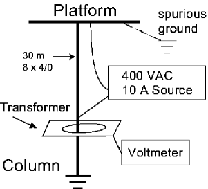
As the construction of a detector is very complicated and done by many people, we had a significant concern that the grounding plan would be inadvertently violated. Therefore we built a Ground Integrity Detector (GID), a device which checks to see if there is an electronic path to ground other than the intended single point ground. The device sends an AC 400 Hz signal current through the ground leads and then checks whether all current is returned. It enables us to have a dynamic determination of the integrity of the ground.
The physical layout, which is depicted in Fig. 5, consists of a grounded stanchion with a welded on boss for mounting a current transformer. The boss has a flange to secure the 4/0 cables used to ground the platform. The current transformer detects current in the boss. A supervisory current (400 Hz) is sent through the 4/0 cables from the cable flange to the platform. The transformer does not see this current. If an extraneous path from the platform to ground is accidentally created then that current must pass through the current transformer. The voltmeter will detect this current.
The current transformer output consists of a voltage proportional to the current through the mounting boss. To guard against false readings due to 60 Hz leakage current, the signal must be filtered. The electronics consists of two 400 Hz bandpass filters in tandem preceded by a 300 Hz high pass circuit. The output of the second band pass filter is fed to an active rectifier chip and then to a Simpson controller. The controller provides relative voltage (proportional to extraneous 400 Hz current) as well as preset visual and audible alarm functions.
The eight 4/0 cables are used as a single point ground and are the safety ground for the electronic platform The DC and 60 Hz impedance of the cable array is approximately 0.7 m. However the 400 Hz impedance is about 1.7 m. If a droplight that was connected to another power source were inadvertently hung on the platform, the ground wire in the cord would provide a leakage current to the supervisory current. The magnitude of the leakage current is dependent on many factors, but is typically 300 mA. This value provides a current transformer output of 350 mV at 400Hz. The detector has a sensitivity of 100 mA = 0.168 or about 30 m of number 12 wire.
9 Fiber and Cable Plan
The STAR detector differs from previous collider detectors as much of the digitization is on the detector. This design requires that low voltage power cables are the largest volume of cables entering the detector. Because of grounding and the desire to reduce the size of the power supplies, the low voltage power supplies locally provide power to the detector from the platform. These cables were routed from the platform to radial cable trays on the magnet face. All of the data, except for the trigger detector, goes directly from the inner section of the detector and then is routed to the south platform and then to a very simple group of movable supports. At the end of the supports, the cables pass through a concrete tunnel to the DAQ room.
The readout between the detector and Data Acquisition Room is almost entirely made up of fiber optical cable. Because adding connectors in these cables attenuates the signal and reduces the reliability, it was decided that the detector readout chain must be left intact and never broken. Consequently, we designed a flexible overhead “festoon” system for transporting the fiber cable bundle from one hall to the other. This system required the addition of approximately 35 meters of fiber to the total cable run of approximately 100 m.
The festoon easily moves as the detector travels from the WAH to the AH. As a result there is no need to disconnect the data cables when the detector is moved. As the South Platform is rigidly tied to the magnet, there was no need to disconnect the power cables from the detector.
The distance via the cable trays between the South Platform and the detector vary by as much as 11 m because the trays are routed on the radius of the Magnet. If the cables were cut to length, then there would be different timing for signal cables and different resistive losses for power cables. Because we desired that the cable effects be similar, we decided that all similar types of cable should be cut to the same length. This decision resulted in us having significant amounts of excess cable. These surplus lengths were stored in cable trays that run under the second and third floors of the South Platform, and under each floor of the South Platform. The floors were designed so that there was easy access to the cable trays. A typical length for a cable from the South Platform to the detector is 35 m.
10 Water Systems
The STAR Facilities have as part of their conventional systems a stand alone water system. The Detector, in full operation, dissipates approximately 4 MW of electrical power through various closed loop water systems with heat exchange to an open air cooling tower.
The magnet closed loop system is a Low Conductivity Water (LCW) system dissipating 3.2 MW using 1100 gpm @ 200 psi while maintaining the aluminum coil assemblies at a mean temperature of 29 C with a T of 11 C. Because the conductor is aluminum, all materials in this system are restricted to aluminum and stainless steel with a water resistivity greater than 5 M-cm. This system goes through two heat exchanges. the first time with the cooling tower as a pre-cooler, and the second with a chiller system used during the warmer months of the year.
Detector electronics, represents approximately 160 kW of power that is dissipated through the Modified Chilled Water (MCW) system. This LCW closed loop water system provides 16 C water using 360 gpm @ 150 psi through a heat exchange with a chiller system. There are secondary closed loop systems that operate off a heat exchanger with the MCW system for cooling TPC, SVT, TOFp, and FTPC detector subsystems.
The Magnet DC power supplies and water-cooled electrical buss are another closed loop water system that dissipates 340 kW through a heat exchange with the cooling tower. As mention previously, both the Magnet and MCW water system dissipate a large portion of their heat, in the warmer months of the year, through a heat exchange with a water chiller system. These 2 - 200 ton capacity chillers are capable of dissipating the 1220 kW load from both the magnet and MCW systems in a heat exchange with the cooling tower.
Programmable Logic Controllers (PLC) control all water systems with alarm and interlock capability. The system can be monitored in the STAR Control Room through an interactive schematic display of the system parameters of each water system.
11 Beam Pipe
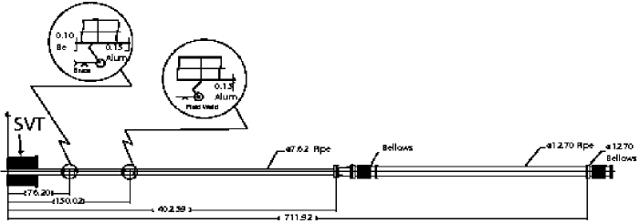
The beampipe assembly for STAR spans the 16 m width of the experimental hall. Located at the edges of the hall are the two interaction region vacuum pumps. The beampipe near these pumps is 12.7 cm in diameter; but it necks down to only 7.62 cm at 4 m from the interaction point (IP). A layout of the beam pipe can be seen in Fig. 6.
The goal for the beampipe and pumping system design is to maintain a vacuum in the torr range at the IP in order to minimize beam-gas interactions. One of the more challenging aspects of the design was to maintain this level of vacuum while minimizing the mass of the beam tube and supports within the constraints of a nearly hermetic collider detector. As is typical of most collider experiments, there are many detector elements that cluster close (within a few cm) to the beampipe and extend the full length of the detector. Additionally, these subdetectors must be installed and removed for maintenance along the beam axis. This means that the opportunities for supporting the beampipe are few and far between. The last structural item of significant mass is located over 4 m from the IP.
To minimize the material near the IP, we use a cone structure fabricated from a carbon fiber-epoxy/Nomex honeycomb material that holds the Silicon Vertex Tracker (SVT) to support the beam pipe. At 54.8 cm from the IP, a spider arrangement of 4 aluminum radial wires (3.18 mm diameter), 4 G-10 insulating rollers (7.19 mm diameter by 25.4 mm long) and a disk (128 mm O.D. by 89 mm I.D. by 6.4 mm thick) fixes the beampipe to the SVT cone. The SVT cone then attaches to the TPC wheel, which is mounted to the magnet.
While the beampipe outside the STAR detector is 1.5 mm Stainless Steel, as it transitions to the smaller 7.62 cm diameter within the detector it becomes 1.24 mm thick Aluminum, then at 76 cm from the IP becomes 1 mm wall Beryllium.
This design utilizes a single standard length of rolled Beryllium tube at the heart of the detector. To reduce the cost, the length of the Beryllium is limited and a thin Aluminum section is welded to it. This economical choice only minimally impacts the number of secondary or stray particle hits in the SVT and TPC. The Beryllium is cleaned and passivated to minimize oxidation and Be dust so that it safer to handle. It was joined via braising to a short 6061-T6 aluminum transition and welded to an Aluminum/Stainless Steel “Conflat” flange by the manufacturer. After arriving at the STAR experimental hall, the end was cut and additional lengths of aluminum tubing were field welded in place to make up the full-length 8.08 m pipe.
Many considerations come into play in determining the beam tube wall thickness. The thickness is a pseudo-optimization of acceptable safety factor from “critical buckling pressure” calculations, the allowable mid-span/mid-support deflections as well as standard or available tube wall thickness and the necessity to be able to handle and transport the pipe. The analyses included the reduced material strength and stiffness at bakeout temperatures (150 C for Aluminum), the imperfections in tube “roundness”, and the extra weight and space requirements of bakeout blankets. We selected a safety factor between 3 and 4. This value produces a relatively robust design that should survive the occasional maintenance and upgrade situations while minimizing both the multiple coulomb scattering for particles that are produced inside the beam pipe and the secondary particles that are created by the beam pipe.
12 Mechanical Movement of the Detector
The STAR Detector must move 33 m between the Assembly Hall, where maintenance and upgrades occur, to the Wide Angle Hall. Mechanical movement of the 1100 Tonne detector is accomplished hydraulically using the inchworm principle. A set of thick rail plates, on which the 4 - 500 ton Hillman Rollers ride, are imbedded in the hall floor perpendicular to the detector (beam) axis. These plates have a repeated hole pattern for bolting the base of the 30-Ton hydraulic actuators used to move the detector in approximately 1.5 m increments. These actuators both push (extend) and pull (retract) with similar load carrying capability.
The detector was designed and constructed with the cylindrical axis 1.3 cm below beam height, when resting on the Hillman Rollers and floor rail plates. When the detector is moved into the WAH, it is raised vertically to beam height and supported using 4-1000 ton hydraulic actuators, which act as four legs of a table. These actuators are inverted with their pistons pushing against the floor rail plates and their upper bases pushing against the main support carriage. Between the pistons and the floor rail plates are electrical isolator compression pads. Electrical isolators are also used between the Hillman Rollers and the floor rail plates, once the detector is raised to electrically isolate the detector from the building. There are mechanical locking collars on each piston to support the detector load when hydraulic power is removed. Both the horizontal and vertical actuator motions are controlled using a closed loop servo system allowing for precise control of motion parameters of both individual or combined actuator systems.
The detector is restrained from motion in both the Assembly and Wide Angle Halls by the seismic supports. These 4 large devices restrain the detector in the horizontal plane, while maintaining the electrical isolation preventing multipoint grounding. The seismic supports are capable of constraining the detector from 0.25 g horizontal accelerations.
The 2 - 100 ton pole tips on the East and West ends of the detector form the end pieces of the cylindrical magnet steel. They must be removable for accessing the internal detector elements. This is accomplished using a pole tip support carriage for each pole tip. Each carriage weighs 70 tons and is capable of lifting and retracting or inserting the pole tip through vertical, tilt, and linear hydraulic actuator motion. Once the pole tips are inserted, the carriages can be disconnected and retracted away from the detector.
13 Performance
The design of STAR took many years to complete. Tools such as 3D CAD were used to simulate the detector and the assembly. Even with this very careful planning process, it was not possible to foresee all the ramifications of our decisions. It certainly could be possible that an overlooked detail could create a fundamental conflict in the assembly of the detector. Furthermore, we had to carefully manage any last minute changes. These items could introduce delay into the project and increase the cost. Furthermore, an unmanaged change could negate the planning processes. The following sections describe our experience as the detector was assembled and subsequently operated.
13.1 Assembly
The assembly of all detector elements went very smoothly. The sub-systems were monitored in reviews to make sure that the designers understood the envelope drawings and interfaces. Any change in their design was carefully reviewed to make sure that the ramifications of the modification were understood and changes to other detectors were minimized.
There was no need to modify or retrofit any part of any detector due to interference with a neighboring element. Nor was there a need to change any items due to mismatch at an interface. There was also adequate room for all power and signal cables, gas pipes, cooling lines and structural support elements. Up front thinking and system level design (envelope and interface drawings, interface specifications) of the STAR detector proved very worthwhile.
13.2 Movement of the Detector with the Festoon
The detector typically moves between the WAH and AH once per year. The operation of stepping the detector the 33 m from one hall to the other requires 4 hours. Setup and safety checks require a significant fraction of this time.
The festoon lets us rapidly operate the detector after it is moved. When the festoon was first assembled, the only copper cables were a safety/interlock and a trigger bundle cable. After the initial operation, the copper trigger cable was disconnected and replaced by an optical fiber connection. As a 1 cm optical fiber carries all of the data from one of the 24 TPC sectors, the size of the festoon is small. The total diameter of the full cable bundle is about 15 cm. This amount includes all of the TPC, EMC, SVT, FTPC, trigger and miscellaneous cables. This size is very small compared to cable bundles that previous collider detectors needed.
When access is needed to the inner detector, it is necessary to remove the pole tips. The time to disassemble both the magnet water and electrical connections and then move the pole tip out of the way is about 8 hours. The time to restore the pole tip so that the Magnet can be operated is approximately the same time.
13.3 Grounding
As the detector was built, it often became hard to balance the requirements of low capacitance with the physical requirements of the detector. Also, the capacitance of the detector to the walls of the building was neglected in the design.
In the early stages of the design when just the Magnet and North and South Platforms were attached, the total capacitance was about 14 nf. This number is significantly higher than the planned number of about 5 nf. After the detector was fully assembled, the final value was about 130 nf. First, this number was measured with the pole tips retracted from the magnet. This particular stray capacitance is not seen when the detector is taking data. Secondly, a number of sub-systems were not installed as planned. For instance, several gas pipes were installed very close to the North Platform, and several cable runs ran on the concrete floor.
When the detector was installed, the GID showed that there was in fact a stray path to ground. This path vanished when the detector traveled to the Assembly Hall and the fault came back intermittently when the detector returned to the WAH. After much investigation, a small metal chip was found which shorted across a detector insulator.
The GID is designed to measure a ground fault of 0.17 . At one time, we tried to measure the capacitance of the detector and found that there was a 400 ground fault. Such a large number could not be measured with the GID and could only be done by disconnecting all ground cables. Similarly, the GID is not designed to measure the capacitive coupling. A careful measure of the true impedance coupling of the detector to the environment can only be done when the ground connection is disconnected. This is not practical to do often, as this measurement requires all power to be turned off the detector.
Tests show there is no significant external electrical contribution to the detector noise from the surroundings for the TPC pedestals. Measurements made show that even with the magnet operating at full current, the pedestals are about 1.1 ADC counts. This value is approximately the same as measured in the laboratory.
13.4 Rack Cooling
The rack cooling supplies need to hold the interior rack temperatures low enough to minimize electronic aging. The water system was originally designed to operate at 16 C. However, the water temperature had to be increased to 19 C so that condensation would not happen inside the racks. The higher temperature was needed because the air conditioning system could not dehumidify the air sufficiently when the outside temperature was hot and the outside humidity was high.
Even though the water system ran at a much higher temperature, the VME crate temperatures typically operate at 23 C, about 2 C above ambient temperature and a very comfortable temperature for electronics. Even the highest temperature in a crate was only 27 C.
Several factors contributed to this good fortune. First, the preliminary estimates of the power loads in the crates turned out to be high. For a DAQ crate, the final value was approximately 700 w/crate, which is about 1/2 of the original projection. Furthermore, the flow for the cooling water was specified to be 8 l/min for each radiator. The cooling system exceeded these specifications. The flow in the DAQ heat exchangers varied between 12 to 18 l/min with the highest flow value at the bottom of the rack.
We could have operated the input water temperature at an even higher water temperature. However, the temperature of the TPC water system was coupled to the rack water system and any higher temperature made the TPC cooling system unstable. Consequently, on the most extreme hot and humid days, there was condensation in the crates. When this condition happened, the leak detection system promptly detected the moisture and turned off the power so that the moisture did not damage the electronics. A new dehumidifier system has been added to the WAH air conditioning system to eliminate this condition for the next run.
14 Conclusion
The team of integration and system level engineers and physicists was crucial to building the detector on time and on budget. The planning worked well and as a result the final mechanical and electrical environment for STAR was built as intended.
References
- [1] K.H. Ackerman et al., Phys. Rev. Lett. 86, 402 (2001).
- [2] C. Adler et al., Phys. Rev. Lett. 86, 4778 (2001).
- [3] See the other articles about STAR in this volume.
- [4] The other envelope drawings can be found on the STAR web site, www.star.bnl.gov.
- [5] National Bureau of Standards, Guideline on Electrical Power for ADP Installations, Publication 84, (1983).
- [6] W. Kampmeir, Preliminary Design Report for the Grounding, Surge Protection and Noise Reduction for Electrical Power Distribution at the IR Region, SDC-SGT-00016 (1992).
- [7] H. Matis and R. Jared, Grounding Requirements Document for STAR, Controlled STAR Note 202A, found in the documents section of the STAR Web site, www.star.bnl.gov.
- [8] R. Jared et al., Requirements for Safety Interlocks for the STAR Detector, Controlled STAR Note CSN361A, (1998), www.star.bnl.gov.
- [9] W.B. Christie, Requirements for STAR Global Interlock System, CSB361B, (1999), www.star.bnl.gov.
- [10] Allen-Bradley, Milwaukee, WI, USA.
- [11] M. Haldeman, S. Holm, and B. Merkel, IEEE Trans. on Nucl. Sci., 33, (1986) 825.