WEAP051 Development of the Simulator for the Global Orbit Feedback System using EPICS
Abstract
We have carried out the basic research for the accelerator and tokamak control system based on the Experimental Physics and Industrial Control System (EPICS). We have used the process database and the state notation language (SNL) in the EPICS to develop the simulator which represents as a virtual machine. In this paper. In this paper, we introduce the simulator of the global orbit feedback system as an example. This simulates the global orbit feedback system under the constraint conditions for Pohang Light Source (PLS) storage ring. We describe the details of the feedback algorithm and the realization of the simulator.
1 Introduction
When the beam position change takes place during the conventional global orbit correction processes, the photon beam through the beamline is affected, and it results in the alignment of mirrors and monochromators. This is particularly severe for a long beamline such as the undulator beamlines. This problem can be overcome by introducing a local bump at the particular beamline. However, for some light sources, there are not enough corrector magnets to generate local bumps as much as needed. This difficulty can be overcome when we correct the COD under the condition where the beam positions at particular points are not changed. This is our main objective to develop a method of the closed orbit correction under constraint conditions.
2 Theory
2.1 Ordinary COD correction and regularization
The beam position is normally described as a vector measured by beam position monitors (BPM). In order to correct the COD, we need corrector magnets with their strengths described as a vector . When the corrector magnets kick a beam, the new beam positions can be described as follows.
| (1) |
Here, is called the response matrix of dimensions whose components are given by
| (2) |
where is the betatron tune of the storage ring, and and are the beta function and the phase function for the BPM and corrector magnet, respectively. In order to reduce the COD, we have to choose the kick of each corrector magnet satisfying
| (3) |
It is called the PSINOM algorithm[1].
The COD correction is actually a minimization procedure of defined as
| (4) |
By using the relations of vector operators which are hyper-dimensional gradient operators, we can get the same result of PSINOM algorithm as shown in eq. (3).
This algorithm includes an inversion procedure of the matrix . In some cases, we can get unacceptable corrections due to the ill-posedness of . A regularization method is introduced to avoid this problem. In this case, is written as
| (5) | |||
| (6) |
where is the regularization parameter. Then the minimum corrector kicks can be determined by
| (7) |
This equation represents the modified PSINOM algorithm, and we can relax the inversion problem of the singular matrix by using the diagonal matrix when is singular[2].
2.2 Method with constraint conditions
After having the new closed orbit with the minimum distortion from eq. (7), the new orbit is generally different from the original orbit. Sometimes, this difference can be taken place at very sensitive locations such as the entrance and the exit of an undulator. If the beamline is well aligned for this undulator, a COD correction should be avoided in this region. A constraint condition can be described in terms of the beam position at BPM such as
| (8) |
Here, is the row of the response matrix . Also, and are the beam positions before and after the correction, respectively. Since we want to keep this position unchanged, should be zero. If there are BPMs involved in the constraint condition, we can write the constraint condition as follows.
| (9) |
Here, is the () sub-matrix of the response matrix. Each component of corresponds to the BPM involved in the constraint condition. We also assume that has a non-trivial solution.
We now add this constraint condition to the modified PSINOM algorithm to obtain the new such as,
| (10) | |||
| (11) |
Here, is the Lagrangian multiplier, and it is an dimensional vector. By following the derivative to the corrector strength, we can get the vector which minimizes the closed orbit distortion outside the constraint region such as,
| (12) |
Here, we define the square matrices of dimensional and dimensional as follows.
| (13) | |||
| (14) |
Eq. (12) can be rewritten as
| (15) |
Now, we can remove the Lagrangian multiplier in eq. (12) by using the above equation. Then, we can finally get the kick values of the corrector magnets as follows.
| (16) | |||
| (17) |
3 Development of simulator using EPICS
The algorithm developed in the previous section has been successfully tested for the Pohang Light Source (PLS) operation. The new correction code is written in C language and it is installed in one of the operator consoles which is a SUN workstation. Although the PLS control system is not using Experimental Physics and Industrial Control System (EPICS) which is used in many accelerator laboratories world-widely, there is a plan to upgrade the control system based on EPICS technology[3, 4]. As a part of such upgrade activity, we have started the development orbit correction algorithm with EPICS. Since we do not have any EPICS-based control system yet, we decide to develop the orbit correction simulator using EPICS.
In order to seek the way to adopt our orbit correction algorithm into EPICS, we have considered two ways: one is based on the subroutine record and the other is using the state notation language (SNL) program. The first method needs new record support that runs the orbit correction algorithm. To do this, the correction code is required to be written upon the protocol required by the record support such as the entry structure and the callback structure. This approach gives relatively fast response because this method uses database access and can access the record by process passive mode[4, 6]. This is a good feature for the realtime system but the large portion of the orbit correction code we have already tested must be rewritten according to the protocol of the record support.
One of important tasks of EPICS input/output controller (IOC) is the sequencer that runs programs written in SNL. The SNL considers the control object as the state machine and treats transitions between states. The sequencer monitors the transitions for the SNL and runs callback functions using the entry table the corresponding program written in SNL. Since the sequencer accesses to the record via channel access (CA) and the record access is only possible through non-process passive mode, there are some restrictions in access time or the treatment of records. However, this method can directly imbed the program written in C language. Also, unlike the subroutine record, this method can remove program tasks without rebooting the system, which gives the code debugging very easy[4, 5]. Thus, the second method gives more benefits when the system does not require heavy realtime demands. Upon reviewing the two methods, we have decided to use the latter method.
3.1 SNL program
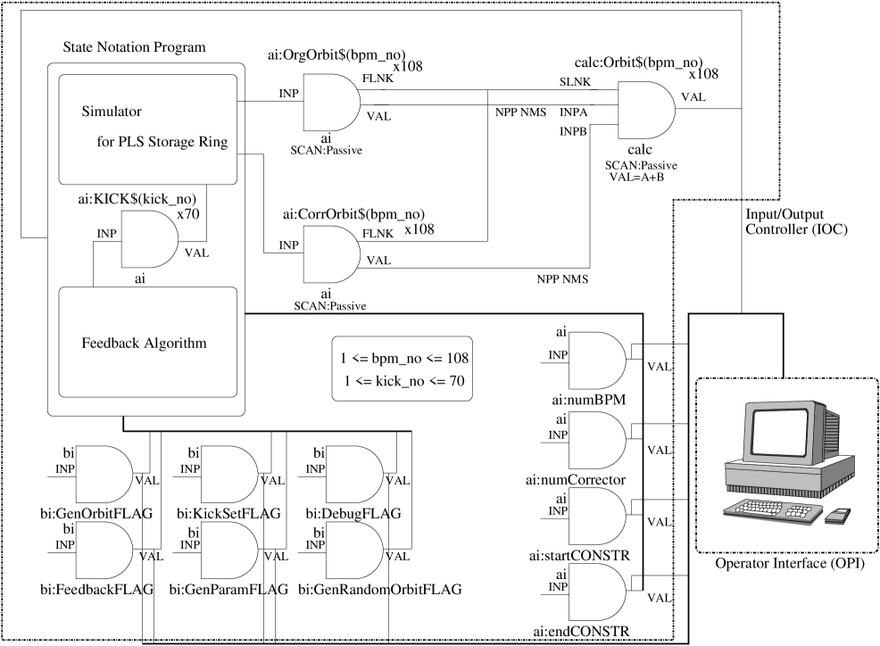
The orbit correction simulator is developed in IOC level and has the SNL program imbedding C codes and several database records, as shown in Fig. 1. There are two parts in the SNL program: one for the feedback including the orbit correction algorithm and the other for the simulator which emulates the PLS storage ring. The latter calculates orbit changes from ai:KICK$(kick_no) records which store the corrector strengths obtained from the response matrix measured at the PLS. This process is actually a product of matrix and column vectors. The calculated orbit changes are stored at ai:CorrOrbit$(bpm_no) records. In the next step, the corrector strengths s calculated by the algorithm described in the previous section and the results are stored at al:KICK$(kick_no).
3.2 Database and record linkage
The SNL program we have developed consists of four state sets. Since they are linked together and interacted dynamically via EPICS database, we need to understand the database and its records as well as the linkage between them. The ai:KICK$(kick_no) record uses the analog input record to represent the corrector strength. There are 70 records altogether as representing 70 correctors in the PLS storage ring. They are linking the simulator and the feedback in a parallel manner. The index $(kick_no) is the integer value between one and 70.
The records of ai:OrgOrbit$(bpm_no) and ai:CorrOrbit$(bpm_no) are the orbit distortion before the feedback is applied and the orbit change after the feedback, respectively. They are using analog input records. Since these records represents the changes at the PLS BPM, $(bpm_no) is the interger value between one and 108. The superposition of these two records gives new orbit. This can be done by the calculation record calc:Orbit$(bpm_no). Since this calculation record is linked forwardly from ai:OrgOrbit$(bpm_no) and ai:CorrOrbit$(bpm_no), the superposition is newly calculated whenever the values of two records are changed.
On the other hand, ai:numBPM, ai:numCorrector, ai:startCONSTR, and ai:endCONSTR are representing the BPMs and correctors used in the correction algorithm, start and end point of the constraint region, respectively. They are using analog input records and notifying the SNL program if necessary.
The other records are binary input records and they are representing necessary status flags. They are used as the mediator of state transitions between state sets in the SNL program.
4 Conclusion
We have developed the COD correction algorithm under the constraint condition where the beam position at particular point is not changed. The new algorithm is based on the modified PSINOM algorithm which includes the regularization process in order to avoid the inversion problem of the ill-posed response matrices.
We have confirmed that this algorithm is working well and is in good agreement with the experimental results [7]. Even though the PLS is planning to upgrade their control system with EPICS, there is no working EPICS based control system at PLS. Due to this, we have developed the orbit correction simulator using C-code embedded SNL program based on EPICS technology. This simulator part can be replaced by the real control system with minor changes after the completion of the upgrade.
References
- [1] W. Herr: ”Algorithms and procedures used in the orbit correction package COCU,” CERN SL/95-07 (AP), 1995.
- [2] Y. N. Tang and S. Krinsky: Proc. AIP Conf. 315 (AIP Press, 1993) 87.
- [3] See URL”http://www.aps.anl.gov/epics”
- [4] Martin R. Kraimer: ”EPICS IOC Application Developer’s Guide,” APS/ANL, 1998
- [5] Andy Kozubal: ”State Notation Language and Sequencer User Guide,” LANL, 1995
- [6] Philip Stanley, et al.: ”EPICS Record Reference Manual,” LANL, APS/ANL, 1995
- [7] Kukhee Kim, Jinhyuk Choi, Tae-Yeon Lee, Guinyun Kim, Moohyun Cho, Won Namkung, In Soo Ko: Jpn. J. Appl. Phys. 40 (2001) 4233.