Thin Ice Target for 16O experiment
Abstract
A windowless and self-supporting ice target is described. An ice sheet with a thickness of 29.7 mg/cm2 cooled by liquid nitrogen was placed at the target position of a magnetic spectrometer and worked stably in the 16O experiment at MeV. Background-free spectra were obtained.
PACS: 25.40.Ep; 27.20.+n; 29.25.-t
keywords:
Windowless and self-supporting ice target; Background-free spectrum of oxygen., , , , , , , , , , , , , , , , , , , , , , , , , , , , and
1 Introduction
The 16O nucleus is an important target for the study of nuclear physics because of the spin-saturated closed-shell property. Extensive measurements of [1], [2, 3, 4], [5], [6], and [7] reactions have been devoted to investigate various nuclear properties, e.g. excited resonance structures, single particle or hole states and, effective interactions in the nuclear medium.
It is, however, not easy to prepare an 16O target due to its gaseous property. Table 1 summarizes the types of the oxygen targets and their characteristics. Metal oxides are commonly used as oxygen targets since their preparation in a chemical process is relatively easy. The solid compositions of BeO and Li2O are conveniently used in many experiments. Recently, a thin SiO2 (glass) target has been successfully employed for the coincidence measurement of decay particles from the deep-hole state excited by the reaction [8]. In order to extract the oxygen events, however, the events from the metal base should be measured separately and subtracted. This procedure often includes intrinsic problems concerning the statistics and quality of spectra. When we use a thin target, the evaluation of the contamination in the metal base is also difficult.
Oxygen gas kept in a cell is also used as a target. At backward scattering angles, the events from the cell windows can be removed by means of a double-slit collimator. At forward angles, however, this is not so easy; again the subtraction procedure is needed. Moreover, the effective thickness changes with scattering angles depending on the slit geometry. The long cell length needed to assure enough target thickness makes it difficult to use the ray-tracing technique in combination with a magnetic spectrometer. A “water fall” target, in which water flows membranously in a target cell, has been used at several facilities [9, 10]. This target is normally thick, more than 25 mg/cm2.
A windowless gas target can be obtained by injecting a supersonic gas jet into a vacuum chamber and immediately evacuating the gas by pumps [11, 12, 13], but this gas-jet target is too thin (maximum 1 mg/cm2). In addition, a gas-jet target is very expensive since it requires a large pumping and gas recycling system due to a high gas-flow rate ( m3/h). A differential pumped target, which keeps vacuum with orifices by reducing gas flow, is also windowless [14]. However, it is thinner than a gas-jet target. A differential pumped target is usually used in low energy experiments.
Recently new types of experiments have become feasible to measure the decay of charged particles from highly excited states in coincidence with , and (3He,) events at intermediate energies [8, 15, 16, 17, 18]. Information from these measurements may be combined with those from polarization transfer observables [19] in order to study microscopic structures of highly excited states. The detection of decay charged particles requires a thin target to minimize the energy loss. In addition, some free space is needed around the target to install detectors for charged decay particles.
An frozen H2O target was developed for the use as an oxygen target at Los Alamos National Laboratory (LANL) [20, 21], and it was successfully used in a experiment [5]. Unfortunately, since the LANL target was rather thick ( mg/cm2) and included window foil to prevent the ice from sublimation, it is not suitable for the detection of charged decay particles. Frozen H2O targets are, however, attractive because of the high density and also because hydrogen events can be removed easily by using a large difference of the kinematical effects between hydrogen and oxygen. In addition, there is no excited state of hydrogen in our excitation energy region ( MeV). It is estimated that sublimation loss of ice in the vacuum can be neglected if the ice sheet-target is kept under very low temperature. Vapor-pressure of H2O is of the order of Pa at 140 K and decreases exponentially at lower temperature. Window-foil, therefore, is not needed below 140 K.
Possible heating up of the ice target by the irradiation of the beam is estimated. The temperature distribution on the ice target is described by the following equation at the stationary state;
| (1) |
where denotes the thermal conductivity and denotes the volumetric heat generation rate. The rise of the temperature by the energy loss of the proton beam was estimated under the simple assumptions. If the axial symmetry of the target disk is assumed, Eq. (1) can be easily solved with the boundary condition that K at the edge of the copper frame and K at the center of the target. Temperatures at the center of the 30 mg/cm2-thick ice target obtained from Eq. (1) are 93.4 K and 97.8 K for the proton beam intensities of 10 nA and 100 nA, respectively. The calculated temperatures are much lower than the critical temperature of 140 K.
In this article, we describe a windowless and self-supporting ice target developed at the Research Center for Nuclear Physics (RCNP), Osaka university. The performance of the ice target as the oxygen target examined in a experiment is presented.
2 Preparation of Ice Target
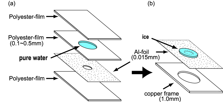
The process to make an ice sheet-target is illustrated in Fig. 1. At first, 15 -thick aluminum foil with a hole of 10 mmϕ is prepared and a spacer polyester film with a larger hole is placed on top of it. Since the target thickness is mainly determined by the thickness of the spacer, an appropriate thickness should be selected. The polyester films with thicknesses mm were used to make mg/cm2 thick targets. They are further covered by polyester films from both sides as shown in Fig. 1(a).
As a next step, a few drops of pure water are carefully poured into the hole space made by the spacer. The amount of water is adjusted depending on the desired thickness of the target taking the density of the ice (0.92 g/cm3 at 0∘C) into account. The whole stack is cooled in the freezer box of a refrigerator. Then, keeping the ice frozen, the covering polyester films and the spacer polyester film are carefully removed. The minimum thickness of 10 mg/cm2 has been achieved with a skilled and careful treatment. The aluminum foil with the ice sheet on top of it is mounted on a pre-cooled, 1mm-thick copper frame with a 20 mmϕ hole as shown in Fig. 1(b).
Finally, the mounted ice sheet is slowly cooled by nitrogen vapor from liquid nitrogen (LN2) in order to avoid cracking. Cracks in the ice sheet cause the deterioration of thermal conductance. The direct contact between an ice sheet and the copper frame should be avoided since thermal stress due to the difference of thermal compressibilities between ice and copper causes cracking of the ice. The soft aluminum foil plays a crucial role in reducing the stress and keeping enough thermal conductivity. It is better to reduce the amounts of material around the ice sheet in order to avoid the background events from the beam halo. The thin aluminum foil is also preferable from this view point. The hole size of 10 mmϕ is much larger than the beam spot size of 1 mmϕ.
3 Target Cooling System
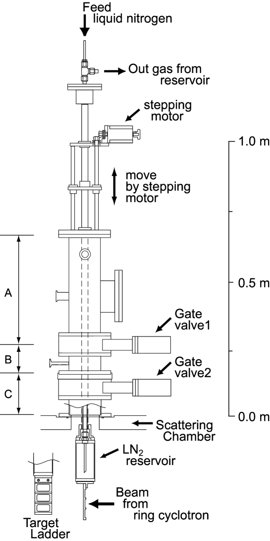
A schematic view of the cooling system for ice targets is shown in Fig. 2. LN2 is fed from the top of the apparatus and stored in the reservoir above the target ladder made of copper. LN2 is introduced to the reservoir through the central part of the triple concentric pipe, and vaporized nitrogen gas is exhausted through the middle pipe. The space between middle and outside pipes is kept in vacuum to insulate the heat. Since the target ladder is directly connected to the reservoir, it is cooled down to about 90 K, a temperature only slightly higher than that of LN2 (77 K). The temperature is monitored by thermocouples. An automatic liquid nitrogen feeding system is used. Liquid nitrogen is fed in every 3 hours and the feeding stops when the reservoir becomes full. The consumption of liquid nitrogen is 1.5 kg per 3 hours. This system is mounted on top of the scattering chamber of the spectrometer Grand Raiden [22]. The vertical position of the target can be changed by using a stepping motor, which is controlled remotely via the RS-232C connection.
The installation of the ice target is done in the following procedure. Initially the target ladder is pre-cooled by LN2 without any ice targets, and the parts denoted as A and B in Fig. 2 are removed from the scattering chamber in order to mount the ice targets. This process is done without breaking vacuum of the scattering chamber or the target container (part A) by closing the gate valve 1 and 2; only the vacuum of the part B is broken. After nitrogen gas is introduced to the part A, the target ladder is pushed out of the part A through the gate valve 1. Then the ice target cooled by the nitrogen vapor from LN2 is quickly mounted on the target ladder. As soon as the target is mounted, the target ladder is pulled back and the part A is pumped out to lower than Pa. Finally, the parts A and B are connected with the part C on the scattering chamber and the target ladder is installed into the scattering chamber.
4 Experiment and Results
The 16O spectra were measured using a 392 MeV proton beam at RCNP ring-cyclotron facility. A proton beam extracted from the ECR (Electron Cyclotron Resonance) ion source was accelerated by the = 120 MeV AVF (Azimuthally Varying Field) cyclotron, and was further boosted to higher energies by the = 400 MeV ring-cyclotron. The emmitance of the beam was defined by slits between the AVF cyclotron and the ring-cyclotron. The extracted beam was achromatically transported from the ring-cyclotron to the scattering chamber of the two-arm magnetic spectrometer system (for details, see, for example, Ref. [23]). The ice target was bombarded by a proton beam with a maximum intensity of 10 nA. The beam spot size was about 1 mm in diameter. The vacuum in the scattering chamber was kept lower than Pa. Scattered protons from 16O were momentum analyzed by the high-resolution spectrometer Grand Raiden [22] placed at several angles between 2.5∘ and 14.0∘. Protons scattered by 1H were measured by using a large acceptance spectrometer (LAS) [24]. A proton beam was stopped by a Faraday cup in the scattering chamber for the measurements at backward angles from 4.0∘ to 14.0∘. In the measurements at forward angles from 2.5∘ to 4.0∘, another Faraday cup placed between Q1 and SX magnets of Grand Raiden was used in order to avoid interference with scattered protons.
A typical spectrum of the inelastically scattered protons from 16O is shown in Fig. 3. The energy resolution was 150 keV (FWHM). The spectrum consists of discrete levels at lower excitation energies and broad resonance bumps at higher energies. Since the target was kept near to the LN2 temperature, contaminations due to the congelation of residual gases on the target surface may happen in principle. However, we could not recognize any significant peaks due to the contaminations, suggesting that the spectrum is background-free.
The target thickness can be changed by both the congelation and the sublimation process. In order to check the stability of the target thickness, elastic scattering events from hydrogen were monitored by LAS [24] placed at for 7 hours in the experiment. Due to the large momentum transfer in the backward proton-proton scattering, the proton-proton elastic peak was unambiguously identified. Thus, we could easily extract the yield of the elastic peak on the continuum by assuming the smooth distribution of the quasi-elastic events. The absolute cross section of proton-proton elastic scattering at at 392 MeV was calculated using the SAID program [25] based on the partial-wave analysis of various experiments. By comparing the calculated cross section with the measured result from LAS, the thickness of the ice target was determined to be 29.7 mg/cm2. The variation of the target thickness is shown in Fig. 4 as a function of the irradiation time. The target thickness remained stable (within the 2.5 % measurement uncertainty) during the entire 7 hour irradiation time.
5 Summary
A method to prepare a windowless, self-supporting and low-cost ice target has been described. The produced ice target was successfully used to measure the spectra of inelastic proton scattering from 16O. A ice target of about 30 mg/cm2 worked stably. The target thickness was monitored for 7 hours by measuring p+p elastic scattering and no meaningful variation of the thickness was observed. Furthermore, no obvious effect of contaminations due to the congelation of residual gases on the target was detected. Since a thin ice target was made, measurements of charged decay particles in coincidence with inelastically scattered particles are possible.
References
- [1] N. Voegler, J. Friedrich, E.A.J.M. Offermann, C.W.de Jager, and H. de Vries, Phys. Rev. C 43 (1991) 2172.
- [2] B. Larson, K. Hicks, O. Hausser, R. Abegg, W. Alford, A. Celler, D. Frekers, R. Helmer, R. Henderson, K.P. Jackson, R. Jeppesen, J. Mildenberger, C.A. Miller, B. Pointon, R. Schubank, M. Vetterli, and S. Yen, Phys. Rev. C 53 (1996) 1774.
- [3] H. Seifert, J.J. Kelly, A.E. Feldman, B.S. Flanders, M.A. Khandaker, Q. Chen, A.D. Bacher, G.P.A. Berg, E.J. Stephenson, P. Karen, B.E. Norum, P. Welch, and A. Scott, Phys. Rev. C 47 (1993) 1615.
- [4] C. Djalali, G.M. Crawley, B.A. Brown, V. Rotberg, G. Caskey, A. Galonsky, N. Marty, M. Morlet, and A. Willis, Phys. Rev. C 35 (1987) 1201.
- [5] D.J. Mercer, J. Rapaport, C.A. Whitten, Jr., D. Adams, R. Byrd, X.Y. Chen, A. Fazely, T. Gaussiran, E. Gulmez, C. Goodman, D.W. Huang, G. Igo, A. Ling, D. Marchlenski, D. Prout, L. Rybarcyk, E. Sugarbaker, and T.N.Taddeucci, Phys. Rev. C 49 (1994) 3104.
- [6] R. Abegg, D.A. Hutcheon, C.A. Miller, L. Antonuk, J.M. Cameron, G. Gaillard, J.M. Greben, P. Kitching, R.P. Liljestrand, W.J. McDonald, W.C. Olsen, G.M. Stinson, J. Tinsley, and P.D. Kunz, Phys. Rev. C 39 (1989) 65.
- [7] C.A. Miller, K.H. Hicks, R. Abegg, M. Ahmad, N.S. Chant, D. Frekers, P.W. Green, L.G. Greeniaus, D.A. Hutcheon, P. Kitching, D.J. Mack, W.J. McDonald, W.C. Olsen, R. Schubank, P.G. Roos, and Y. Ye, Phys. Rev. C. 57 (1998) 1756.
- [8] M. Yosoi, H. Toyokawa, N. Tsukahara, H. Akimune, I. Daito, H. Ejiri, H. Fujimura, M. Fujiwara, T. Ishikawa, M. Itoh, T. Kawabata, M. Nakamura, T. Noro, E. Obayashi, H. Sakaguchi, H. Takeda, T. Taki, A. Tamii, M. Uchida, T. Yamada, and H.P. Yoshida, in Proceedings of Workshop on Frontiers in Nuclear Physics (Suwon, Korea, Feb. 18-19, 2000), edited by H. Bhang, M. Fujiwara, and B.T. Kim, to be published.
- [9] N. Voegler, and J. Friedrich, Nucl. Instr. Meth. 198 (1982) 293
- [10] F. Garibaldi, E. Cisbani, R. Crateri, S. Frullani, F. Ghio, F. Giuliani, M. Gricia, M. Iodice, M. Lucentini, L. Pierangeli, F. Santavenere, G.P. Capitani, E. De Sanctis, M. Bernheim, J.F. Danel, J.E. Ducret, L. Lakehal-Ayat, J.M. Le Goff, A. Magnon, C. Marchand, J. Morgenstern, P. Vernin, and A. Zghiche, Nucl. Instr. Meth. A 314 (1992) 1.
- [11] J. Ulbricht, G. Clausnitzer, and G. Graw, Nucl. Instr. Meth. 102 (1972) 93.
- [12] G. Bittner, W. Kretschmer, and W. Schuster, Nucl. Instr. Meth. 161 (1979) 1.
- [13] M. Taiuti, E. Durante, M. Anghinolfi, N. Bianchi, P. Corvisiero, E. De Sanctis, G. Gervino, C. Guaraldo, P. Levi Sandri, V. Lucherini, L. Mattera, V. Muccifora, E. Polli, A.R. Reolon, G. Ricco, P. Rossi, M. Sanzone, and G.M. Urciuoli, Nucl. Instr. Meth. A 297 (1990) 354.
- [14] K. Sagara, A. Motoshima, T. Fujita, H. Akiyoshi, and N. Nishimori Nucl. Instr. Meth. A 378 (1996) 392, and references therein.
- [15] H. Akimune, I. Daito, Y. Fujita, M. Fujiwara, M.B. Greenfield, M.N. Harakeh, T. Inomata, J. Jänecke, K. Katori, S. Nakayama, H. Sakai, Y. Sakemi, M. Tanaka, and M. Yosoi, Phys. Lett. B 323 (1994) 107.
-
[16]
H. Akimune, I. Daito, Y. Fujita, M. Fujiwara, M.B. Greenfield,
M.N. Harakeh, T. Inomata, J. Jänecke, K. Katori, S. Nakayama,
H. Sakai, Y. Sakemi, M. Tanaka, and M. Yosoi, Phys. Rev. C 52
(1995) 604.
-
[17]
H. Akimune, I. Daito, Y. Fujita, M. Fujiwara, M.N. Harakeh, J. Jänecke,
and M. Yosoi, Phys. Rev. C 61 (2000) 011304R.
- [18] H. Toyokawa, H. Akimune, T. Baba, I. Daito, H. Ejiri, H. Fujimura, M. Fujiwara, T. Inomata, K. Ishibashi, M. Kawabata, T. Kinashi, H. Kohri, T. Noro, A. Tamii, M. Tanaka, T. Yamada, and M. Yosoi, in Proceedings of 8th International Conference on Nuclear Reaction Mechanisms (Varenna June 9-14, 1997), edited by E. Gadioli (Universita Degli Studio Di Milano, 1997), p.606.
- [19] A. Tamii, H. Akimune, I. Daito, Y. Fujita, M. Fujiwara, K. Hatanaka, K. Hosono, F. Ihara, T. Inomata, T. Ishikawa, M. Itoh, M. Kawabata, T. Kawabata, M. Nakamura, T. Noro, E. Obayashi, H. Sakaguchi, H. Takeda, T. Taki, H. Toyokawa, H.P. Yoshida, M. Yoshimura, and M. Yosoi, Phys. Lett. B 459 (1999) 61.
- [20] C. Pacheco, C. Stark, N. Tanaka, D. Hodgkins, J. Barnhart, and J. Kosty, LANL Report No. LA-8109-MS, 1979.
- [21] D.J. Mercer, LANL Report No. LA-12441-MS, 1992.
- [22] M. Fujiwara, H. Akimune, I. Daito, H. Fujimura, Y. Fujita, K. Hatanaka, H. Ikegami, I. Katayama, K. Nagayama, N. Matsuoka, S. Morinobu, T. Noro, M. Yoshimura, H. Sakaguchi, Y. Sakemi, A. Tamii, and M. Yosoi, Nucl. Instr. Meth. A 422 (1999) 484.
- [23] T. Noro, T. Baba, K. Hatanaka, M. Ito, M. Kawabata, N. Matsuoka, Y. Mizuno, S. Morinobu, M. Nakamura, A. Okihana, K. Sagara, H. Sakaguchi, K. Takahisa, H. Takeda, A. Tamii, K. Tamura, M. Tanaka, S. Toyama, H. Yamazaki, Y. Yuasa, H. Yoshida, and M. Yosoi, Nucl. Phys. A629 (1998) 324c.
- [24] N. Matsuoka, T. Noro, K. Tamura, M. Yoshimura, M. Yosoi, A. Okihana, and T. Yoshimura, Phys. Lett. B 359 (1995) 39, and references therein.
- [25] R.A. Arndt, H.O. Chang, I.I. Strakovsky, R.L. Workman, and F. Dohrmann Phys. Rev. C 56 (1997) 3005; solution SP00 from SAID website.
| Type | Merit | Demerit | Ref. |
|---|---|---|---|
| Metal oxide (BeO, Li2O, …) | Easy to obtain. | Large background events from metal base. | [3] |
| Gas target (Max ) | Relatively clean. | Difficult to obtain enough thickness. Background events from window foil. | [4] |
| Gas-jet target Differential pumped target (Max ) | Clean. No window foil. | Expensive, Limited areal density. | [11, 12, 13] [14] |
|
Water fall
()
Ice () |
Easy to subtract background from hydrogen. | Background events from window foil. | [9, 10] [20, 21] |