Single-neutron transfer from 11Begs via
the (p, d) reaction with a radioactive beam
Abstract
The 11Be(p, d)10Be reaction has been performed in inverse kinematics with a radioactive 11Be beam of MeV. Angular distributions for the ground state, the , 3.37 MeV state and the multiplet of states around 6 MeV in 10Be were measured at angles up to by detecting the 10Be in a dispersion-matched spectrometer and the coincident deuterons in a silicon array. Distorted wave and coupled-channels calculations have been performed to investigate the amount of core excitation in 11Begs. The use of “realistic” 11Be wave functions is emphasised and bound state form factors have been obtained by solving the particle-vibration coupling equations. This calculation gives a dominant 2s component in the 11Begs wave function with a 16% [21d] core excitation admixture. Cross sections calculated with these form factors are in good agreement with the present data. The Separation Energy prescription for the bound state wave function also gives satisfactory fits to the data, but leads to a significantly larger [21d] component in 11Begs.
PACS: 25.60.Je, 24.10.Eq, 21.10.Jx, 27.20+n
keywords:
NUCLEAR REACTIONS: 1H(11Be, 10Be) = 35.3 MeV, 1H(15N, 14N) = 38.9 MeV; measured ; deduced spectroscopic factors; vibrational coupling model. Radioactive beam., , , , , , , , , , , , , , , , , , , , and
1 Introduction
The nucleus 11Be is of especial interest for several reasons. As is well-known, the ground state spin-parity is in contradiction to the simple shell model and spherical Hartree-Fock prediction of . This “parity inversion” is correctly predicted by, for example, recent psd-shell calculations of Brown [1]. The intruder orbital is lowered by the non-central part of the particle-hole interaction [2]. Moreover, 11Be is often regarded as the classic one-neutron halo nucleus: the small single-neutron separation energy of 505 keV together with an assumed -wave nature of the valence neutron leads to a very extended spatial distribution [3, 4].
Several calculations of the 11Be ground state structure have been performed. The theoretical approaches include: the shell model [5, 6], the variational shell model [7], the Generator Coordinate model [8], and coupling of the neutron with a vibrational [9, 10] or rotational core [11, 12]. Most of these models correctly reproduce the parity inversion and high-energy reaction data, but make very different predictions about the degree of coupling of an s1/2 neutron to the 10Be ground-state core relative to a d5/2 neutron coupled to a excited core (the first excited state of 10Be at 3.368 MeV).
A direct test of the models for the structure of 11Begs may be made by measuring the relative cross sections of one-neutron pick-up reactions feeding the 0+ and 2+ states of 10Be. Transfer cross sections depend on the overlap between the wave functions of the initial and final states through the radial neutron form factors (r). Standard distorted wave Born approximation (DWBA) analyses assume that these form factors are proportional to single particle wave functions (r), so that one may calculate cross sections independently of any prior assumption about the structure of initial and final states, apart from an overall normalisation factor. The latter is the spectroscopic factor, which is defined as the product of the overlap integral and a factor [13], where in the present case is the neutron occupation number of the 2s1d shell in 10Be. If one expresses the wave function of the 1/2+ 11Be ground state as the sum of the single particle and core excited components
| (1) |
the spectroscopic factors S(0+) and S(2+) for transfer to the ground and first excited state of 10Be should be directly related to and , respectively, assuming negligible population of the 2s1d orbitals by 10Be core neutrons.111Strictly speaking, and should be equal to the fractional parentage coefficients, the squares of which add up to unity. The relation between these and spectroscopic factors is given in the Appendix and Ref. [13]. Table 1 gives spectroscopic factors deduced from the various models cited above. These spectroscopic factors vary widely. For example, the standard Shell Model [5, 6] predicts S(0+) = 0.74 and S(2+) = 0.19, while the Variational Shell Model [7] gives S(0+) = 0.55 and S(2+) = 0.40. Also given in the table is the ratio = S(2+)/[S(0+) + S(2+)], which provides a measure of the amount of the admixture in the wavefunction. This ratio shows large variations, although all models agree that the admixture is smaller than the 2s component. The dominance of the 2s component is also the conclusion of some recent experimental investigations [15, 16]. However, the precise amount of core-excitation in the 11Be ground state wavefunction remains uncertain.
| S(0 2s) | S(2 1d) | ||
|---|---|---|---|
| Variational shell-model (Otsuka et al. [7]) | 0.55 | 0.40 | 0.42 |
| PVM (Bhattacharya & Krishan [10]) | 0.70 | - | - |
| CC rotational coupling (Nunes et al. [11]) | 0.78 | 0.20 | 0.20 |
| Shell-model (Warburton & Brown [5, 6]) | 0.74 | 0.19 | 0.20 |
| Vibrational coupling (Vinh-Mau [9, 14]) | 0.80 | 0.20 | 0.20 |
| CC-DC (Esbensen et al. [12]) | 0.87 | 0.10 | 0.10 |
| Generator-Coord. (Descouvemont [8]) | 0.92 | 0.07 | 0.07 |
The present paper describes an approach to the 11Begs structure through the 1H(11Be, 10Be)2H inverse-kinematics radioactive beam reaction. Data were also obtained for the 1H(15N, 14N)2H reaction at 584 MeV for comparison with the (p, d) reaction as measured in normal kinematics [17]. Our (15N, 14N) measurement provided an important cross-check of the analysis methods, particularly in regard to the calculation of the deuteron/heavy-ion coincidence efficiency and the ability to eliminate background from reactions on carbon.
Brief accounts of the experiment have been presented in Refs. [18, 19, 20]. Preliminary data were reported in Ref. [19] together with the first results of a standard DWBA analysis, which used single-particle form factors evaluated according to the usual Separation Energy (SE) prescription for the bound state wave functions. Spectroscopic factors deduced from that preliminary analysis [19] indicated a large [21d] admixture in the 11Begs wave function, exceeding most theoretical predictions. However, that interpretation was valid only to the extent that the radial wave function (r) of the transferred neutron in 11Be, relative to a 10Be core, may be approximated by the product of the SE single-particle form factor and a spectroscopic amplitude. This assumption is questionable in view of the large deformation parameter (=0.74 [21]) of the final nucleus 10Be, which could induce important coupling effects. These core-coupling effects may change the radial shape of the neutron wavefunction in a manner dependent on the angular momentum. This can directly affect the inferred spectroscopic factor deduced from transfer-reaction cross sections. The latter mainly depend on the squared amplitude in the surface region of the nucleus. In Ref. [20] we presented the results of DWBA calculations which used bound state form factors evaluated in the framework of the particle-vibration coupling model. These more sophisticated calculations indeed gave a significantly smaller [21d] admixture in the 11Begs wave function compared to the results with the SE wave functions. In the present paper, the vibrational coupling results are shown to be consistent with calculations which use radial form factors from the rotational excitation model of Nunes et al. [11]. In addition, we present calculations which include coupling to inelastic channels, and discuss the most significant factors not included in the direct transfer calculations.
The structure of the paper is as follows: After the experimental details (Section 2), the features of the spectra are discussed (Section 3). Next, we explain the extraction of the cross sections (Section 4), which is followed by a section on the analysis of the angular distributions with the distorted wave Born approximation (DWBA), including an estimation of the effect of coupling to inelastic channels (Section 5). The results are summarised and discussed in Section 6.
2 Experimental Details
2.1 Beams and targets
The secondary 11Be beam was produced by fragmentation of a 65 MeV/nucleon 15N beam from the GANIL cyclotrons, which bombarded a carbon target of thickness 1.03 g/cm2 located between the two superconducting solenoids of the SISSI device [22]. The 11Be beam was analysed by the “alpha” spectrometer, which was operated as a fragment separator and had a 216 mg/cm2 aluminium achromatic degrader to reject unwanted ion species. After the degrader, a small amount of He and Li isotopes remained in the beam which was 93% 11Be. The magnetic rigidity of the second stage of the “alpha” spectrometer and beam line after the degrader was 2.377 Tm, which corresponded to an average energy of 388.3 MeV ( MeV) for the 11Be ions. With these settings, the intensity of the 11Be particles was about pps for A of 15N, and the energy spread was 4.0 MeV. The full width at half-maximum (FWHM) spread of the incident beam angle at the reaction target was measured to be approximately 1.5∘ horizontally and 0.4∘ vertically
The 11Be beam was brought to a dispersive focus at the target, with a physical size of approximately 5 cm in width and 1.4 cm in height. By comparison, the aperture in the target frame was 10 cm by 3 cm. The principal target used in the experiment was a polypropylene (CH2CHCH3)n foil of thickness m and density 0.896 g/cm3. The nominal target thicknesses were cross-checked by comparing the energy-loss of the 15N direct beam (without degrading) with stopping-power and range tables [23]. Data were also collected with empty target frames during the course of the experiment, from which it is deduced that less than 2% of the counts in the 10Be-gated focal plane spectra originated from the target frame or other sources, rather than from the polypropylene target. For the 11Be beam, data on a 7.24 mg/cm2-thick carbon target were taken for background subtraction purposes in the singles spectra, as discussed in Section 3.
For the 1H(15N, 14N)2H reaction, the 15N primary beam was degraded in energy by a 745 mg/cm2 carbon foil in SISSI to 584 MeV (38.9 MeV/A), so as to more nearly simulate the properties of the 11Be beam. The resulting spread in the incident beam angle at the reaction target was about 0.5∘ horizontally (FWHM) and 0.3∘ vertically (FWHM), which was somewhat smaller than that for the 11Be beam. The size of the beam spot for the degraded-energy 15N at the secondary reaction target was also smaller than that for the 11Be, being approximately 4 mm wide and 4 mm tall at half maximum.
2.2 Dispersion-matched (“energy-loss”) magnetic spectrometer
The energy spread of 4 MeV in the incident 11Be beam, if not compensated in some way, would make it impossible to separate 10Be ejectiles in different excited states. The necessary compensation was achieved by the dispersion-matched magnetic spectrometer, SPEG [24], in which the initial ‘analysis’ beamline has a momentum dispersion = 9.86 cm/%. The spectrometer after the target is tuned to match the dispersed beam spot. In this way, all particles with the same reaction Q-value can be arranged to arrive at the same position along the focal plane.
The SPEG spectrometer was placed at a central angle of , with the acceptance slits set to vertically and horizontally. The focal plane was instrumented to detect the 10Be ejectile nuclei. Momentum and angle measurements were provided by two XY drift chambers [25] of the focal plane detector. This allowed the reconstruction of the position spectrum at the focal plane, which was at a slight angle to the normal to the mean particle trajectory. Unambiguous particle identification was achieved through a combination of the energy-loss signal from an ionisation chamber, the light output from a stopping plastic scintillator, and the time-of-flight measured by the scintillator relative to the cyclotron rf.
The unreacted 11Be beam was stopped in an active “finger” of plastic scintillator material placed at the high momentum side of the focal plane. The scintillator was coupled to a phototube and the light output and time signal were recorded in the acquisition system by a separate, downscaled trigger. This allowed the elimination of the He and Li contamination in the beam, as well as the electrons from the decay of the stopped 11Be (half-life 13.8 s), and thus provided a true count of the number of incident 11Be particles.
The calibration of the focal plane in terms of the particle momentum (and hence excitation energy) was performed with a well-collimated 15N beam incident on a thin Au target with the spectrometer centered at . The magnetic field of the spectrometer was changed in 1.5% steps, two above and two below the central field setting, and the centroid of the elastic scattering peak recorded. With the same beam and target, a mask with a pattern of holes was placed 65 cm after the target for the angle calibration, which was performed at each of the five field settings used for the momentum calibration. The horizontal and vertical angles at the focal plane, and , respectively, were measured at each setting. The horizontal and vertical positions at the focal plane, and , were also measured. With these calibration data, the horizontal angle at the target could be calculated directly from the measured . The optical properties of the spectrometer mean that is independent of and the other parameters. However, the vertical focussing is such that the vertical angle and the vertical position are mutually dependent. This is an important effect for the present experiment, noting that is equally as important as in determining the reaction angle. Further, the vertical extent of the secondary beam spot at the target position, , is large for a secondary beam. To first order, the optical transport of SPEG in the vertical plane can be written as:
| (2) |
with the four coefficients depending on and the momentum difference measured relative to the central momentum, . These coefficients have been determined from the angle-mask calibration runs and the microchannel plate calibration described in Section 2.4. The measured and values were then inverted to determine and the less-important in the data analysis. The uncertainty in was deduced by re-analysing the calibration runs with the final coefficients applied and was found to be for both the 11Be and 15N runs, despite the smaller emittance of the latter beam.
2.3 Beam tracking detectors
The angles of the incident beam particles were measured event-by-event using two XY position sensitive drift chambers [26] located before the “analyser” magnet of the SPEG spectrometer, separated by 1 m from each other. This position was chosen in order to eliminate the products of any scattering or nuclear reactions inside the detector material. Each chamber consisted of four modules such that both X and Y were measured twice, but in opposite senses (to eliminate multiple coincident hits). The approximate overall dimension of each chamber was cm3. They were filled with isobutane gas to a pressure of 20 mbar and each chamber had a total thickness of approximately 0.65 mg/cm2 CH2 equivalent, including 4 m of mylar in the gas-window and field-shaping foils. The timing signals from each module, relative to the focal plane plastic scintillator of the spectrometer, were fed into a multi-hit TDC. More than one X or Y signal from a given chamber could thus be recorded in a single event (triggered by the spectrometer focal plane). Correlated pairs of X and Y times from each chamber were then selected by the data analysis software, by requiring that the sum of each pair should add up to a constant. If one measurement of an X-pair was missing in a given chamber, and if the time for the X-signal that was present was unique, the X-position could be recovered knowing that constant, although this was only required for a few percent of the total events. The combined efficiency of the two chambers for complete XY determination was approximately 88% for the 11Be beam and 96% for the 15N beam.
Since several magnetic elements in the beam line lay between the XY-tracking detectors and the target, the incident angles at the target needed to be cross-calibrated against the measurements at the tracking detectors. A tightly-collimated beam was sent through to the spectrometer focal plane with no reaction target in place. The currents in two horizontal and vertical steering magnets were then systematically changed, to steer the beam at different angles through the tracking detectors, and thence through the spectrometer. The difference signals and from the tracking detectors were then related to the previously-calibrated and from the focal plane detector.
2.4 Microchannel plate
A position-sensitive microchannel plate detector [27] was placed approximately 60 cm in front of the target and was used as a diagnostic device, as well as to calculate the aberration coefficients in Eqs. 2. It was not used for event-by-event correction of the deuteron angle because of poor detection efficiency. However, it was used to estimate the size of the beam spot, which in turn was used as input to the Monte-Carlo simulation program to calculate the coincidence efficiency as will be discussed in Section 4.1. The horizontal position was calibrated by stepping a tightly-collimated beam across the detector using the analysing magnet field. The vertical position was calibrated using a dispersed beam by illuminating a thick target which had a small hole in the centre, and stepping the target ladder up and down. A further calibration was performed with an -source by placing a mask with a pattern of holes immediately in front of the detector target foil.
2.5 Detector array for coincident light particles
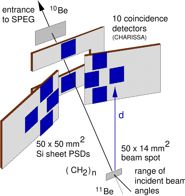
The recoiling deuterons were detected in an array of ten position-sensitive sheet-resistive silicon detectors (CHARISSA) mounted in the target chamber. Each detector was cm2 in area and 500 m thick. These are the same detectors as used in the MEGHA array [28]. They were arranged around the space joining the extended beam spot and the spectrometer acceptance aperture, as shown in Fig. 1, and spanned angles between and relative to the central point on the target.
The energy signals of the detectors were calibrated with a 3-line -source and the source peaks were monitored during the experiment. The position signals were calibrated with the -source, by placing masks with a pattern of holes over the detector faces. The coincidence timing between the silicon detectors and the spectrometer focal-plane (taken from the plastic stopping detector) was set using the reaction 1H(15N, 15N)1H at = 584 MeV in kinematic coincidence, with the spectrometer moved temporarily to and each CHARISSA detector moved in turn to .
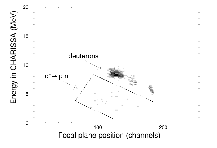
The kinematics of the energy signal from the silicon detector as a function of the momentum of the 10Be in the focal plane allows deuterons to be distinguished from protons arising from the (p, d p + n) reaction. This is shown in Fig. 2.
It was not possible to use a similar technique to separate the protons from deuteron breakup in the (15N, 14N) data, because the higher beam energy in that case meant that the deuterons were not in general stopped in the silicon detectors.
Being less sensitive to the incident beam angle [29], the deuteron angle proved useful for the beam angle calibration. Also, the vertical angle, after the appropriate kinematic transformation to the heavy-ion angle, could be used as an alternative to discussed above. The further use of the deuteron angle was limited by the large size of the beam spot at the target.
2.6 Electronics and data acquisition
Standard NIM and CAMAC electronics were used to process the signals from the preamplifiers. The principal triggers for the standard GANIL VME-based acquisition system were: (i) a SPEG focal plane event, (ii) the downscaled beam in the plastic “finger”, and (iii) a CHARISSA “singles” event. The latter was used only as a diagnostic. The data words for event-type (i) included a bit-pattern that indicated which, if any, CHARISSA detector had recorded a hit in coincidence. The time correlation was also recorded between the silicon signal and the heavy-ion in order to reject random coincidences. The data were recorded on magnetic tape and were independently analysed off-line at the IPN-Orsay and at the University of Surrey.
3 Discussion of Focal Plane Spectra
3.1 14N spectra

Focal plane position spectra for the (15N,14N) reaction at MeV on the polypropylene target are shown in Fig. 3. The peak from the reaction on protons leading to the 14N g.s. dominates the spectrum. The experimental energy resolution is about 540 keV (FWHM). Calculations using the formulae given in Ref. [29] show that the combined uncertainty in the angle measurement and target effects contribute about 470 keV to this, leaving a contribution of about 270 keV from the spectrometer optics which corresponds to a momentum resolving power of approximately one part in 4300.
The coincidence measurement (lower panel) removes the reactions arising from the carbon in the target, as well as possible background from 15N N + n breakup, seen in the singles spectrum (upper panel). Other states observed in 14N are the 2.313-MeV level and the second level at 3.948 MeV. All these states were seen in the 15N(p ,d) experiment of Ref. [17], and with a similar ratio of strength to the present data. In the singles spectrum (upper panel), weak yield to low-lying states in 13C from the 12C(15N,14N)13C reaction is observed. The peak immediately to the left of 13C ground state at about 3.9 MeV excitation, and of similar width to the ground state peak, is assigned to 13C excited to 3.854 MeV rather than 14N excited to 3.948 MeV. The latter assignment is unlikely, since the peak would be broadened by inflight -emission to an estimated width of about 1.36 MeV. The excitation energy of 13C (possibly mutual with 14N) for the broad peak near channel 225 is MeV.
3.2 10Be spectra
The 10Be focal plane position spectra for reactions with the 11Be beam were accumulated at two different magnetic field settings separated by 0.9%, for a total number of incident 11Be particles. Only the data for the first field setting, amounting to roughly 6/7th of the total, were used in the final analysis.
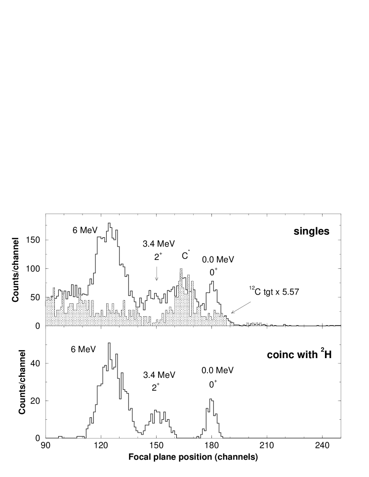
The (11Be, 10Be) singles spectrum is shown in the upper panel of Fig. 4. The low-lying states of 13C from 12C in the target are at most weakly observed; as a reference point, the ground state for 13C is expected at channel 222. In contrast, there is a strong yield to states at high excitation, such as the peak at channel 165, corresponding to an excitation in 13C of MeV, or, more likely, to mutual excitation of 13C to MeV and of 10Be to 6 MeV. This strong yield contaminates the peaks from the reaction on hydrogen. The carbon-scattering origin of these counts is proved both by their absence in the spectrum taken in coincidence with deuterons in the CHARISSA array (Fig. 4, lower panel) and their presence in the singles data taken on a pure carbon target (Fig. 4, overlay on upper panel). The preferential population of high excitation states in 13C (with an assumed structure) agrees with Q-value and angular-momentum matching considerations [30]. The coincidence spectrum (Figure 4, lower panel) shows clean separation from other counts for the ground state and the first excited state (3.368 MeV, ) of 10Be. As observed in the case of the 15N beam spectra, the coincidence measurement very effectively removes the background which principally arises from the stripping reaction on the carbon in the target.
The energy resolution for the ground state peak is about 700 keV. The angle uncertainty and target straggling accounts for only about 250 keV of this, from which we deduce that the contribution from the spectrometer optics was some 650 keV. This corresponds to a momentum resolving power of approximately one part in 1200, which is considerably worse than that observed for the (15N, 14N) reaction and is presumably a consequence of the larger beam spot size in the (11Be, 10Be) case.
All the peaks corresponding to 10Be excited states in the spectra are broadened by gamma decay of the nuclei in flight. The measured fwhm of the peak for the 3.37 MeV state is MeV. The maximum spread (i.e. base width) from the recoil-broadening is = 1.89 MeV, where is the average 10Be velocity. If one assumes an isotropic angular distribution of -rays, giving a sin() dependence to the spread, the estimated fwhm is 1.26 MeV, in agreement with observation. Full treatments of the effect on the broadening when the angular distribution of the -emission is known are given by Beene and Devries [31] and Pelte and Schwalm [32].
The dominant peak in the 10Be spectra arises from transfer to a group of four closely-spaced levels near 6 MeV excitation. Kinematic matching [30] does not especially favour the 6 MeV region in 10Be, thus the strong yield to this region reflects a strong overlap of initial and final states. One explanation of the intense “6-MeV peak” is the pickup of one p3/2 neutron in 10Be core, feeding the (s1/2,p) 1- and 2- states at 5.960 and 6.263 MeV. There might also be smaller contributions of neutron pickup to the second 2+ and 0+ states at 5.958 and 6.179 MeV. However, an alternative, although not necessarily incompatible explanation invokes the two-centre shell-model [33, 34]. In the two-centre shell-model, the 11Be nucleus is described as two alpha particles and three orbiting neutrons [35]. The removal of a neutron should leave 10Be in a similar two-centre orbit configuration. In the case of 10Be the most strongly-coupled configurations are not associated with the ground state but with the states around 6 MeV [36, 37]. We note also that the two-centre shell model can also account for the inversion of the s- and p- states resulting in the 1/2+ ground state in 11Be. This is because of the lowering of the component of the deformed d5/2 orbitals.
In the singles spectrum, the peak at 6 MeV is superimposed on a background corresponding to the high energy tails of the (11BeBe + n) and (dp + n) break-up reactions near thresholds. The residual nucleus 10Be is unbound to particle emission above 6.812 MeV, so no further peaks are expected above this multiplet. As previously discussed in Section 2.5, the contribution of the (p, pn) reaction to the 10Be spectra has been removed by energy conditions in CHARISSA which select coincident recoil deuterons.
4 Extraction of Cross Sections
In this section, we present a description of the simulation program used to estimate the particle detection efficiencies, which is needed for the extraction of the cross sections from the deuteron coincidence data. All the cross sections presented in this paper are those from the analysis of the coincidence spectra. Despite the larger number of counts in the peaks, the cross section extraction from the singles spectra has no better statistical accuracy than that from the coincidence spectra, because of the need to subtract a background which is not accurately determined. Analyses of some singles spectra have been performed as a cross-check of the estimation of the coincidence efficiency.
4.1 Detection efficiency
Data in coincidence with the CHARISSA detectors were corrected for the variation of geometrical deuteron detection efficiency as a function of the heavy-ion (10Be or 14N) laboratory angle. This efficiency was calculated by the use of an extended version of a Monte-Carlo simulation program [38], which accounts for the emittance and beam spot size of the secondary beam, and for the uncertainty of the scattering angle determination. Two efficiencies need to be taken into account in the calculation of the coincidence differential cross section. Firstly, the efficiency of detecting deuterons in the CHARISSA array for a given heavy-ion detection angle. Secondly, since the beam spot is large, (particularly for the 11Be beam), not all the heavy ions at an angle less than the nominal spectrometer slits setting (which assumes a point beam spot) will be transmitted. There is a further complication arising from the large variation in incident beam angle. Thus, a second efficiency factor needs to be calculated, which is the ratio of the number of heavy-ion events generated at a given angle divided by the number of counts accumulated in the corresponding “detected” angle bin. The angular resolution of the detection system is also taken into account in the program. This latter is an important effect at small angles, and partly explains the apparently high deuteron detection efficiency near .
Figure 5 shows the calculated efficiencies for the 11Be beam. The beam spot size and envelope were set to simulate the experimentally-measured values given in Section 2.1.

The procedure for the extraction of the coincidence cross sections is to integrate the cleanly-separated peaks and divide by the total efficiency calculated over the appropriate angular range. For several forward angles in the (11Be,10Be) data, where the background from the carbon target is relatively small, it was possible to extract the ground state yield in the singles spectra. The ratio of the coincident to singles yield for the 10Be ions measures the deuteron deuteron efficiency and can be compared to the one calculated by the simulation program. For an angular range between 2.5 to , where the calculated efficiency curve is roughly constant with angle (Fig. 5) the average coincident to singles yield ratio was found to be . This agrees within errors with the average efficiency of 31.4% calculated by the simulation program.
4.2 14N Angular Distributions
Cross sectional angular distributions for the 1+ ground state of 14N are shown in Fig. 6. These are from the analysis of the deuteron-coincident spectra. Other states in 14N were not analysed because of the low yield and the uncertainty in subtracting the underlying background.

The last angle bin extracted is for , corresponding to a mean angle of . In principle, one could go beyond the nominal angular acceptance limit of the spectrometer ( square for a point beam spot, giving a diagonal limit of ) because of the spread in incident beam angle. However, the fall-off in reaction cross section and lack of coincidence efficiency at large angles prevents this.
In Fig. 6 we also show the (p, d) data of Snelgrove and Kashy [17], which were measured at MeV. Our inverse-kinematic data at MeV are in reasonable agreement with the (p, d) data. We conclude that our analysis technique in general, and our simulations of the deuteron efficiency in particular, are reliable at least up to a centre-of-mass angle of for p(15N, 14N)d. For that reaction, corresponds to a deuteron laboratory angle of approximately . If we take the latter as a limit of reliability on the deuteron scattering angle, and apply it to the p(11Be, 10Begs)d reaction, we obtain a rough limit of up to which we are confident in the efficiency simulation. The corresponding limits for the reaction leading to the 3.368 MeV and 6.1 MeV excited states of 10Be are and , respectively.
4.3 10Be Angular Distributions
The final experimental angular distributions for the 0+ and 2+ states and the 6 MeV multiplet are shown in Fig. 7 and tabulated in Table 2. The error bars are statistical. For the four most-forward angle points, the systematic errors arising from uncertainties on the angle determination in SPEG and in the CHARISSA detectors, and on the variation efficiency of the detection system as function of the scattering angle, are estimated to be of the order of 15%. The largest angle points have been revised from the data shown in ref. [20] as a result of a new estimation of the coincidence efficiency [39]. These largest-angle points are close to the limits of the reliability criterion deduced from the (15N, 14N) data above, and are more sensitive to the approximations made for the beam profile, giving an estimated % additional systematic uncertainty from the efficiency calculation. The largest-angle points were not used in the extraction of spectroscopic factors in ref. [20], neither are they so used in the present paper.
| 0.00 MeV | 3.34 MeV | 6 MeV states | |||||
|---|---|---|---|---|---|---|---|
| (deg) | (mb/sr) | (deg) | (mb/sr) | (deg) | (mb/sr) | ||
| 2.50 | 2.62 | 2.73 | |||||
| 5.08 | 5.39 | 5.62 | |||||
| 8.27 | 8.66 | 9.00 | |||||
| 11.60 | 12.15 | 12.63 | |||||
| 15.02 | 15.74 | 16.39 | |||||
5 Analysis of Angular Distributions
5.1 Optical model potentials
Different combinations of optical potentials for the entrance and exit channels have been tried in the calculations presented below, in order to test the sensitivity of the extracted spectroscopic factors to the input parameters. All the optical potentials used in the present analysis have the standard Woods-Saxon or Woods-Saxon derivative form.
For the entrance channel, three principal optical potentials have been used. The most-recent global nucleon-nucleus optical parameterisation is the “CH89” one of Varner et al. [40]. This has dependences on energy, mass and isospin, adjusted for a range of stable nuclei from masses to 209. However, data from recent proton elastic scattering experiments involving 10Be and 11Be radioactive beams (at similar incident energies to the present work) were only reproduced with the CH89 parameterisation if the depth of the real Saxon-Woods well were reduced by a factor of 0.88 [41]. The CH89-derived potential in Table 3 corresponds to p + 11Be at 35.3 MeV with the real well depth adjusted by this factor. Secondly, the 1980 parameterisation of Fabrici et al. [42] was used to generate the proton potential , assuming a deformation parameter for 11Be of zero. Thirdly, the proton-nucleus potential was obtained from the parameterisation of Watson, Singh and Segel [43], which was derived from the analysis of elastic scattering data in the 1p shell.222We note that the spin-orbit parameterisation in Ref. [43] is non-standard, having instead of the usual . Since the spin-orbit potential has little effect on the angular distributions, we have nevertheless kept to the standard form.
| Label | Ref | ||||||||||
|---|---|---|---|---|---|---|---|---|---|---|---|
| [40] | 41.0 | 1.15 | 0.69 | 3.64 | 7.77 | 1.14 | 0.69 | 5.9 | 0.80 | 0.63 | |
| [42] | 56.0 | 1.08 | 0.64 | 3.70 | 3.91 | 1.25 | 0.68 | 5.6 | 1.01 | 0.60 | |
| [43] | 58.4 | 1.12 | 0.57 | 10.39 | 1.12 | 0.50 | 5.5 | 1.12 | 0.57 | ||
| [44] | 76.8 | 1.15 | 0.81 | 23.04 | 1.34 | 0.68 | |||||
| a) | 73.8 | 1.15 | 0.72 | 4.08 | 15.83 | 1.14 | 0.72 | 5.9 | 0.78 | 0.63 | |
| b) | 74.8 | 1.15 | 0.72 | 3.71 | 16.17 | 1.14 | 0.72 | 5.8 | 0.78 | 0.63 | |
| a) | 106.3 | 1.13 | 0.60 | 15.9 | 1.13 | 0.53 | 5.5 | 1.13 | 0.57 | ||
| b) | 107.3 | 1.14 | 0.60 | 16.1 | 1.14 | 0.53 | 5.5 | 1.13 | 0.57 |
a) adiabatic potential for d + 10Begs.
b) adiabatic potential for d + 10Be.
The situation for suitable exit channel scattering potentials is not as satisfactory as that for the entrance channel. A “global” parameterisation may be found in Ref. [44], but it has been derived from the analysis of deuteron scattering on a limited number of targets. No polarised beam data were available at the time that the analysis was made, and so a spin-orbit potential is lacking. This potential, adapted for 36 MeV deuterons, is listed as in Table 3. Zwieglinski et al. [45] also used the Perey and Perey [44] parameterisation in the analysis of their 10Be(d, p)11Be data but added their own spin-orbit potential (depth 7 MeV). Test calculations that we have performed with such an added ad-hoc spin-orbit potential to gave only small differences to the cross sections in the present, rather restricted, angular range of interest.
5.2 Single-particle form factors for a Woods-Saxon well
Theoretical differential cross sections have been calculated using the zero-range DWBA code DWUCK4 [46]. Test calculations were made with corrections for the effects of finite range and the non-locality of optical potentials; in these tests, a finite range parameter of 0.621 and non-locality ranges of 0.85 and 0.54, for nucleons and deuterons, respectively, were used. Differences in the cross sections with and without the finite range correction were found to be less than 10%. The effect of the non-locality correction on the spectroscopic factors was found to be generally less than 20%. For some particular optical potentials, the cross sections changed by about 30%, although in these cases the effect on the and cross sections is correlated to some extent. The DWUCK4 calculations presented here have no non-locality corrections. Transitions to the 0+ ground state and 2+ first excited state were assumed to proceed through neutron pick-up in the 2s1/2 and 1d5/2 orbitals, respectively. The doublet of 1- and 2- states around 6 MeV was assumed to be excited through a p3/2 neutron pick-up from the 10Be core of 11Be.
For the calculations described in this section, bound state neutron form factors were calculated in a Woods-Saxon well according to the usual Separation Energy (SE) prescription [13]. This consists of adjusting the well depth so that the eigenvalue of the Schrödinger equation is equal to the experimental separation energy, thus ensuring correct asymptotic behaviour of the wave function. In the calculations a spin-orbit Thomas term was used with =25 and two different geometries for the Woods-Saxon-well: (1) standard geometrical parameters =1.25 fm, =0.65 fm, and (2) =1.15 fm, =0.57 fm, from the parameterisation of Ref. [43] for p-shell nuclei.
Different sets of optical potentials were used in the generation of the distorted waves in the entrance and exit channels, as detailed in Section 5.1. Attempts to increase the radius parameter of and by 25% to account for the particularly large matter radius [47] of 11Be were not successful in reproducing the present angular distributions, and the geometry given in Refs. [42, 43] was adopted for the production run calculations.
Two fundamentally-different types of deuteron potentials have been used. Potentials deduced from elastic scattering analyses, such as the Perey potential [44], are suitable for standard DWBA calculations. On the other hand, the adiabatic deuteron breakup approximation (ADBA) proposed by Johnson and Soper [48] is generally known to improve the description of (p,d) and (d,p) reactions, by accounting for the effects arising from the break-up of the deuteron in the nuclear field. Such adiabatic deuteron potentials were obtained by folding the neutron and proton global potentials at half the deuteron energy, according to the prescription of Ref. [49]. Potential was derived from the CH89 [40] parameterisation and potential from the Watson, Singh and Segel [43] parameterisation.
These different combinations of optical parameter sets reproduce reasonably well the rapid decrease of the ground state =0 cross section with angle and the rather flat angular distribution observed for the 2+ state and the 6 MeV peak (see examples in Fig. 7). The data in general were poorly reproduced with the global potential [50] extrapolated from (d, d) scattering on nuclei, or the potentials used for analysing 10Be(d, d) data at 12 and 15 MeV [21]. (The results from these “failed” calculations are neither shown, nor are the potentials considered further.) The calculated angular distributions for a given transfer were normalised to the four most forward angle data points by a least square fit procedure, in order to determine the spectroscopic factors . These factors were deduced from the relation , where is the total spin transfer, with the (p, d) zero range normalisation factor of 2.29 [46]. The square of the isospin Clebsch-Gordan, , which is sometimes included in the definition of , is unity for 11BeBe + n.

The spectroscopic factors S() and S() are shown in Fig. 8 for various sets of optical potential parameters. The experimental S(2+) values obtained by assuming a pure d5/2 neutron pick-up change by less than a few per cent if instead an neutron pick-up in the higher-lying d3/2 subshell is considered. The absolute spectroscopic factors strongly depend on optical parameters, with for example a factor of about 1.8 between the S(2+) values obtained with the Perey and Perey deuteron potential and the adiabatic potential . The sum of spectroscopic factors for 0+ and 2+ states, related to the occupation number of the s-d shell in 11Begs, was found to vary between the extreme values of 0.74 and 1.80, with an average value of 1.09. On the other hand, the ratio = S(2+)/[S(0+)+S(2+)] related to the admixture of core excited components in the wave function, is less dependent on the calculation parameters, as shown in Fig. 8.
The average value of deduced from this SE analysis is 0.51, with a standard deviation of 0.09. Note that the lowest values of are obtained from the ADBA calculations with the optical parameter set . These parameters also provide the best fit to the data for angles below , and when SE form factors are used with either geometry (1) or (2) for the binding potential, one obtains values of 0.30 and 0.32, respectively. We therefore deduce a conservative lower limit of 30% core excitation admixture in the 11Begs wave function from the analysis which used single-particle form factors calculated in a Woods-Saxon well with the Separation Energy procedure.
The angular distribution for the 6 MeV peak is well reproduced by calculations for transfer to the 1- and 2- states at 5.96 and 6.26 MeV (see Fig. 7), without consideration of a possible coupling of 11Begs to the 2 and 0 states unresolved in the multiplet. With the optical model parameter set and form factor geometry (1), the summed spectroscopic factor is found to be 1.40. This summed spectroscopic factor is in good agreement with the results of the shell model calculations of Warburton and Brown [5, 6] in an extended 1p-2s-1d basis, which predict spectroscopic factors of 0.69 and 0.58 for calculated 1- and 2- states at 5.96 and 6.23 MeV. However, we recall that this parameter set, , gave the lowest spectroscopic factors for the transition to the 10Be 3.37-MeV state (see fig. 8). Calculations for the 1- and 2- states with parameter set gave a summed spectroscopic factor of 2.69, which is twice the shell model predictions. On the other hand, the shape of the experimental angular distribution suggests that the amount of any or contribution is quite small. The agreement of the calculations with the shell model predictions is thus circumstantial evidence supporting that choice of optical model potentials.

5.3 Effects of core coupling on transfer cross sections
The comparison in the previous section between experimental and theoretical spectroscopic factors is based on two assumptions: (i) a single-particle bound state form factor, and (ii) negligible interference from two-step processes. We have noted in the Introduction the particularly large experimental deformation parameter =0.74 [21], of the 2+ state in 10Be as deduced from (p,p′) data. This might induce significant coupled channel effects on the (p,d) cross sections. In addition, the SE assumption of the proportionality of the bound state form factors to the single-particle wave functions may be a poor approximation if certain basic conditions are not fulfilled. These conditions include having an experimental binding energy close to that expected from the simple shell model and negligible residual interaction between the core and the transferred nucleon [13]. In the case of the pick-up of the halo neutron orbiting around a 10Be core, coupling to the excited core may also modify the radial shape of the neutron wave function in a significant way.
A description of the theoretical formalism and of the calculation of the vibrational form factors is given in the Appendix (further details will be given in Ref. [39]). Briefly, the 11Begs wave function was written in the form given in eq. (1), and a set of coupled equations were solved for the nucleon wave functions. Calculations were performed for both sets of Woods-Saxon well geometries (1) and (2) previously adopted for the SE calculations, and for two different conditions on the deformation parameter value . By adjusting the strength of the real central and spin-orbit potential, the eigenvalues of the coupled equations were made equal to the experimental separation energies.
For the VIB-1 and VIB-2 cases listed in Table 4, the experimental value of 1.84 fm from the analysis of 10Be(p, p′) data [21] was used. The values of the potential depths are given in Table 4. Note the unusually large (about twice the standard spin-orbit value) needed to reproduce the 11Begs parity inversion. A similar result was found by Nunes et al. [11]. In spite of the different radial shapes of (r), similar theoretical spectroscopic factors S and S are deduced from both calculations.
| S | S | S | S | S | ||||||
|---|---|---|---|---|---|---|---|---|---|---|
| VIB-1 | 0.68 | 51.5 | 15.4 | 1.25 | 0.65 | 0.84 | 0.84 | 0.67 | 0.16 | 0.17 |
| VIB-1b | 0.92 | 51.0 | 7.0 | 1.25 | 0.65 | 0.61 | 0.89 | 0.65 | 0.09 | 0.13 |
| SE-1 | 1.25 | 0.65 | (0.66) | (0.28) | ||||||
| VIB-2 | 0.74 | 60.3 | 13.3 | 1.15 | 0.57 | 0.81 | 0.83 | 0.80 | 0.16 | 0.26 |
| VIB-2b | 0.90 | 60.0 | 8.3 | 1.15 | 0.57 | 0.67 | 0.87 | 0.79 | 0.11 | 0.21 |
| SE-2 | 1.15 | 0.57 | (0.79) | (0.38) |
A smaller core-excitation (S), is predicted by the calculations VIB-1b and VIB-2b, which have a more standard, smaller spin-orbit strength, corresponding to a Thomas-Fermi factor of 25. This requires an increased deformation parameter of approximately 0.9 to reproduce the experimental binding energies.
5.3.1 Direct one-step transfer
Theoretical cross sections for direct transfer using external form factors were calculated with the code DWUCK4 [46]. The use of vibrational form factors (normalised to unity) in place of the SE ones in DWBA or ADBA calculations neither appreciably modifies the shape of angular distributions nor the magnitude of the 0+ cross section, but enhances the theoretical cross section for the 2+ state by typically a factor of two. As shown in Ref. [20], the effect of the coupling on the radial wave functions is only minor for s1/2, but significantly shifts the d5/2 form factor outwards, increasing its magnitude by about 40% in the important asymptotic region outside the nucleus. This is responsible for the strong difference between the cross sections calculated with the vibrational coupling model and the SE method. The omission of these coupling effects must cast some doubt on the physical meaning of the S(2+) and values deduced from the SE method, as plotted in Fig. 8. Experimental spectroscopic factors S determined as in Section 5.2 but using vibrational formfactors are given in Table 4. The corresponding ratios, giving the experimental amount of core excitation, range between 0.17 and 0.24, to be compared with the minimum value of 0.30 from the standard SE analysis. The S(0+) and S() values obtained using SE form factors (Section 5.2) are also given (within parentheses) in Table 4 for comparison.
Alternatively, one can use the unnormalized form factors as ingredients in the DWBA calculations and directly compare the predicted cross sections to experimental data. This is done in Fig. 9, which shows the results obtained with optical parameter set , and vibrational form factors corresponding to different well parameters, without any further renormalisation to the data (i.e. the S factors are implicitly used in these calculations). As was the case for the SE method in Section 5.2, the calculated cross sections agree well with the revised last angle data point in the 2+ distribution. Note that the calculated 2+ cross sections are not proportional to the theoretical spectroscopic factors, since the VIB-1 and VIB-2 cross sections differ by a factor 1.5 for the same S value (0.16). The best agreement between experimental and theoretical cross sections for the 2+ state is obtained using form factors VIB-1, calculated with the large spin-orbit parameter ( = 15.4 MeV) needed to reproduce the energy of the excited 1/2- state with the same Woods-Saxon well. By contrast, the VIB-1b and VIB-2b results (with standard spin-orbit strengths and values of ) underestimate the cross section by a factors of 1.4 and 1.9, respectively.

Direct transfer calculations were also performed with radial form factors from the core excitation model (CEM) of Nunes et al. [11]. This model assumes a rotational structure for the 10Be core and possible population of the 2s1/2, 1d5/2 and 1d3/2 by the valence neutron. We have taken spectroscopic factors of 0.85, 0.13 and 0.02 for these levels, respectively (parameter set Be12-b from Ref. [52]). The predicted cross sections, again with the optical parameter set , are shown as dashed lines in Fig. 9. They are rather similar to the results of the vibrational form factors (VIB-1) and reproduce the data fairly well.
The value deduced from the present analysis of the p(11Be, 10Be)d cross sections therefore provides evidence for a dominant () coupling of the halo ground state of 11Be to the ground state of 10Be. The absolute spectroscopic factor depends on the geometry adopted for the neutron well, as might be expected, but it was found not to be substantially modified by the channel coupling treatment of form factors (unlike the case of the transition). Considering the uncertainties from optical potentials alone, the present (p, d) experimental value (0.67 or 0.80, for geometrical parameters 1 or 2, respectively), may be considered in good agreement with the theoretical predictions S of the vibrational coupling model in Table 4.
Both of our experimental and theoretical results for the ground state transition are also in good agreement with the results of two previous (d, p) experiments which used radioactive 10Be targets. These experiments gave spectroscopic factors of 0.73 (Ref. [21]) and 0.77 (Ref. [45]) for incident deuteron energies of 12 MeV and 25 MeV, respectively. One can also compare the (d, p) values for the transition between the 10Begs and the first state at 0.32 MeV in 11Be, 0.63 (Ref. [21]) and 0.96 (Ref. [45]), with our calculated values S which range between 0.61 and 0.84 (Table 4).
5.3.2 Contribution of two-step processes to the 2+ cross section
An important question is whether processes involving inelastic excitation in 10Be and 11Be could contribute to modify the 2+ cross section in a significant way, as did the coupling in the form factor. This has been checked by calculating two-step amplitudes for inelastic excitation followed by transfer (or vice-versa) with the zero range code Cczr [53], which are then added to the direct transfer amplitude (with the appropriate phases). The coupling scheme considered in these calculations is shown at the top of in Fig. 10.

Only one-way coupling was considered for inelastic excitation, as the inelastic coupling strength R was taken equal to the experimental value in 10Be [21] extracted with this assumption. Vibrational coupling form factors VIB-1 have been used for the s1/2 and d5/2 neutron transfers. In addition to the two-step (p, dd′) excitation of the 2+ state via the 0+ ground state of 10Be, possible two-step (pp′,d) paths via 3/2+ and 5/2+ states in 11Be with [2s1/2] configuration, were also considered. These 3/2+ and 5/2+ states are predicted to have an excitation energy similar to that of the 10Be 2+ state (3.37 MeV) by the weak coupling limit of the vibrational model. Experimentally, good candidates for these weak coupling partners of the 2+ state are the unbound levels at 2.69 and 3.41 MeV, with possible Jπ values 3/2+ or 5/2+ [54]. Inelastic coupling strengths and s1/2 neutron form factors of the (p, dd′) path were also adopted for (pp′,d), with the appropriate phases and amplitudes. Results are shown in Fig. 11 for optical parameter sets and , which gave a good description of the 0+ differential cross sections calculated with direct transfer.

For calculations involving inelastic scattering explicitly, where the macroscopic model of a deformed scattering potential is used for the inelastic excitation form factor, the standard d + 10Be optical potential is suitable. On the other hand, adiabatic deuteron potentials are not intended for this application, as these potentials a priori reproduce neither the relevant elastic nor inelastic scattering channels. The results labelled in Fig. 11 have therefore been obtained with the adiabatic deuteron optical potential as the generator of the distorted waves in the (d+10Be) channel, whilst the inelastic form factors were proportional to d/d, the derivative of the standard deuteron optical potential [44].
The enhancement of the 2+ cross section at forward angles from the two-step processes considered here, strongly depends on the optical parameter sets used in the calculations, as they induce large differences in both the direct transfer and the inelastic scattering amplitudes. For , interferences with two-step processes modify the slope of the angular distribution, but do not change the cross section at forward angle by more than 15% relative to single step transfer, so that it is still in agreement with the present data. For , it is seen in Fig. 11 (top panel) that interferences with the (pp′, d) and (p, dd′) paths induce a large enhancement of the 2+ cross section (by a factor of 2.4 at 0∘) relative to direct transfer.
5.3.3 Comparison of full with one-way coupling calculations and effect on the 0+ cross section
Further coupled-reaction-channels (CRC) calculations have been performed with the finite-range program Fresco [55]. These were intended partly as a test of the approximation of restricting the coupling to one-way, as done in the calculations of the previous section. In addition, since the de-excitation of the level is now considered, the effect of dynamical coupling on the cross section can be examined. Finite-range calculations, however, are not compatible with the Johnson-Soper ADBA approach which takes into account deuteron breakup effects, since the adiabatic potential used is obtained from the three-body (core-proton-neutron) Schrödinger equation assuming zero separation between the proton and neutron. Hence the calculations presented in this section use the standard scattering optical potentials . For simplicity, the (pp′d) path through the hypothetical state of 11Be was not included in these Fresco calculations (that through the state was considered). Lastly, all the calculations in this section included the “remnant term” in the interaction potential, normally assumed to cancel in zero-range distorted-wave programs (the effect of the inclusion of the remnant term is discussed below). Thus, for several reasons, the calculated two-step angular distributions are not expected to be similar to those presented in the previous section that used the same optical model potential combination. The couplings considered are shown schematically at the bottom of Fig. 10
In Fig. 12 Fresco calculations are presented for full CRC, for one-way coupling and for the direct transfer alone. The bottom panel of the figure shows that for the transfer leading to the state in 10Be, the difference between the one-way coupling (FR-DW2) and the full coupling (FR-CRC) cross sections is no more than 10%. As previously seen in the ZR calculations of Section 5.3.2, there is a large difference between the one-way coupling and the direct transfer cross sections for this optical model choice.

As regards the transition to 10Be ground state, the FR direct, one-way coupling (now including the 2+ to 0+ de-excitation) and full coupled channels angular distributions all show obvious differences in magnitudes, with the one-way coupling distribution having in addition a small angular displacement in the minimum compared to the others (Fig. 12, top panel). At small angles, the one-way coupling cross section is about 60% of the direct cross section. The FR-CRC cross section magnitude is approximately midway between the two others. At large angles (), the CRC cross section becomes the lowest of the three.
One should be aware of a possible problem with these comparisons, in that the same optical potentials have been used for the direct and coupled-channels calculations rather than refitting the parameters (and the coupling strength) to elastic and inelastic scattering data with the same model, had such data existed. Nevertheless, it seems clear that coupling to inelastic channels could in principle affect not only the 10Be and cross sections, but, more importantly, the ratio .
5.3.4 Effect of the remnant terms in the interaction potential
As mentioned in Section 5.3.3 above, one difference between the finite-range Fresco and zero-range Dwuck programs, is that the former allows the inclusion of the full complex remnant terms (also known as the “indirect” part) in the interaction potential. To be explicit, the prior representation of the interaction for a pickup reaction with is [56]
| (3) |
where is an effective nucleon-nucleus interaction and is the distorting potential used for the entrance channel wave . The binding interaction is the only part from Eq. 3 retained in Dwuck, it being argued that there is considerable cancellation between the “remnant” terms .333In fact the zero-range approximation would make the calculation of these terms difficult since each is a function of different coordinates. However, the cancellation can never be complete, and the omission of these terms negates the post-prior equivalence of the interaction.
From a comparison of the results of one-step Fresco calculations, the cross section for the ground state increases by about 20% when the remnant terms are included whereas that of the excited state is not significantly changed. Thus the ratio of the and cross sections is affected, without the radial wave functions. The remnant terms appear to take into account the radial extent of the wave function being greater than that of the .
5.4 Effect of 11Be recoil excitation and breakup
A new method for analyzing (p,d) reactions involving a weakly bound halo nucleus (C+n) has been developed recently by Timofeyuk and Johnson [57] as an extension to the ADBA. Their adiabatic approach treats the effect of the recoil excitation and break-up (REB) of the halo nucleus on the transfer cross section, by replacing the distorted wave in the p+(C+n) channel by an effective distorted wave, derived from the potential (p+C) according to a definite prescription. The distorted wave function in the (d+C) channel is obtained as in the ADBA, to account for the effect of deuteron break-up on neutron transfer.
The application of this method to the 11Be(p,d)10Be reaction at 35 MeV shows that REB enhances forward angle cross sections of the 0+ and 2+ states, leading to an appreciable reduction of corresponding spectroscopic factors (multiplied by about 0.54 and 0.71, respectively) [57, 58]. Such reductions applied to our results would give a slight increase of and would not change the lower limit determined for the amount of core excitation in 11Begs. The analysis method used in Refs. [57, 58] leads to an value close to 0.5, which falls within the range of values shown in fig. 8. However, it has to be observed that the absolute value of the spectroscopic factor for the 0+ state obtained by Timofeyuk and Johnson even without the REB effects, S(0 [58], is only in agreement with the lowest of our SE analyses, namely, that with the optical potential (note that refs. [57, 58] used the SE-1 geometry for the radial form factors). Their absolute value for S(0+) of with REB is difficult to reconcile with, e.g., the measurement of total reaction cross section [59] and that for high-energy one-neutron removal [16].
6 Discussion and Conclusions
The 1H(11Be,10Be)2H reaction has been investigated in order to provide insight on the structure of the ground state of the halo nucleus 11Be. The analysis has attempted to relate the large cross section observed experimentally for the excitation of the 2+ state at 3.37 MeV with the amount of [21d] core-excited component in the ground state wave function.
An important ingredient in the calculations is the choice of method for calculating the radial wave function of the transferred nucleon in the 11Be nucleus. A common choice, which we have labelled SE, is to calculate the wave function in a Woods-Saxon well, with the depth adjusted to reproduce the known separation energy. Another important ingredient is the use of adiabatic exit channel optical potentials to approximate the effect of the deuteron breakup. We find that any (p,d) reaction analysis using single particle form factors in the SE method will result in a 10Be core excitation admixture 30%. This result would be in agreement with the predictions of variational shell model (42%) [7] although not with most other theoretical models.
However, the validity of the SE single-particle form factors has been brought into question by coupled-channel calculations in the framework of the particle-vibration coupling model. The radial wave function of the d5/2 transferred neutron is found to be strongly modified by the interaction with the 10Be deformed core, enhancing the cross sections relative to the classical SE predictions. One-step transfer cross sections calculated with form factors from the present vibrational coupling approach, or from a core excitation model based on the assumption of a rotational 10Be core [11], are in agreement with the data, and predict only 10 - 20% admixture of the [21d] configuration in 11Begs. Such a dominance of the s-wave component is in agreement with many theoretical calculations (e.g., Refs. [5, 11, 9, 12]).
Because of the large deformation of 10Be, a valid concern is that coupling channel effects may also contribute to the transfer cross sections in a significant way, via two-step (inelastic + transfer) processes. This has been tested by calculations in Sections 5.3.2 and 5.3.3 using rather simple assumptions. The effect of the inelastic coupling could indeed be significant, but it is dependent on the optical model potentials. The breakup of the deuteron seems to have a much more dramatic effect, even to the extent of changing the conclusions that may be drawn, regarding the importance of two-step processes. This strongly indicates that more complete calculations, including a more elaborate treatment of breakup, are required. These are beyond the scope of this work. Effects of 11Be recoil and break-up should ideally also be included, as recent calculations [57] have shown that they could affect transfer cross sections significantly. We have also shown a sensitivity of the calculations to the inclusion of the remnant term in the interaction potential. This appears to affect only the cross section (at the 20% level), and consequently the extracted ratio of spectroscopic factors, is also modified. The necessity of performing both elastic and inelastic scattering experiments in the (p + 11Be) and (d + 10Be) channels at the appropriate incident energy is evident. These are needed to fix the parameters external to the transfer process. It should also be noted that it is the nucleon-core potential, p + 10Be, which is required as input to the ADBA and REB adiabatic calculations.
Three other key experimental results concerning the structure of 11Begs should be considered. Following a demonstration by Suzuki et al. [60] of the sensitivity of the ground state magnetic moment of 11Be to the [ 1d5/2] component of the wave function, a measurement of the magnetic moment has been made at ISOLDE and has given a value of [15]. This result implies a relatively pure 2s1/2 halo state with essentially no 1d5/2 admixture, but a precise interpretation is dependent on the assumed quenching of the single particle magnetic moment. Another recent experiment was a high-energy single-neutron removal (“knockout”) reaction [16] which used a 11Be beam. The authors’ measured cross sections to the particle-bound levels in 10Be agreed well with single-particle cross sections calculated in an eikonal model [61] multiplied by spectroscopic factors from the shell model [5]. It was concluded that 11Be ground state has a dominant 2s single particle character with a small 1d component. The third experiment is the measurement of the total reaction cross section of 11Be [62], which was one of the earliest indicators of the extended halo structure of this nucleus. Reaction calculations [63] can interpret this in terms of the average radius of the halo, which in turn is related to the percentage of s-wave component in the 11Be wave function. The result [59] is that the s-wave fraction is of order 0.8 to 0.9, and larger d-wave admixtures could not be reconciled with the measured cross section.
In conclusion, we have explored the structure of 11Be ground state via a single-neutron transfer reaction with a 11Be radioactive beam. From the experimental point of view, the data presented here constitute a successful implementation of the technique of transfer reactions in inverse kinematics to study the structure of light exotic nuclei, as suggested in, e.g., Refs. [29, 64, 65, 66]. The present “best estimate” of the 11Begs wave function is a dominant 2s component with a 0.16 [ 1d] core-excitation admixture. This value may be better defined by future calculations that principally incorporate a model of deuteron breakup (as well as that of 11Be) within a CRC framework.
Appendix A: Transfer form factors in a vibrational coupling approach
It has long been established that in the presence of core-polarisation admixtures created by an interaction Hamiltonian , radial form factors of one-nucleon transfer reactions should no more be approximated by the product of a spectroscopic amplitude and a single-particle wave function deduced from the standard Separation Energy procedure, but have to be determined by solving the Pinkston-Satchler coupled equations [67]. In the present analysis of the 11Be(p, d)10Be reaction, these coupled equations were solved in the framework of the particle-vibration coupling model [68, 69], with the program CCVIB [51]. The interaction Hamiltonian was chosen as:
| (4) |
where and are operators for phonon creation and annihilation and is the deformation parameter. Here the term d/d corresponds to the deformation of the central part of the potential, with no action on the spin-orbit part. Coupled-channel calculations were performed for both 1/2+ ground state and 1/2- first excited state at 0.32 MeV, with the additional constraint that the same well depth reproduced the experimental separation energies relative to the ground state of 10Be, thus ensuring the right asymptotic behaviour of the wave functions. This reproduction of the separation energies could be obtained by adjusting either the value of the parameter or the strength of the spin-orbit part of the potential. The configuration space was truncated to the 0 and 2 core states in 10Be (first order vibrational coupling), coupled with one neutron in the 1p3/2 or 1p1/2, and 2s1/2 or 1d5/2 orbitals, for the 1/2- and 1/2+ states, respectively.
The resulting wave functions were normalised for each final state according to the prescription . The relative weights of the different configurations are given by the corresponding squared amplitudes . Strictly speaking, spectroscopic factors are defined [13] as the product of the squared overlap integral and , where is the occupancy of the orbital in the core nucleus and is the corresponding single-particle wave function calculated in the same Woods-Saxon potential well. The factors given in Table 4, which are in fact the squares of parentage amplitudes although we call them theoretical spectroscopic factors for convenience, were calculated by assuming and, for the particular cases of s1/2 and d5/2, by approximating the unbound single-particle wave functions , by the bound radial form factors determined by the SE method. They were found to differ from the relative weights by less than 1%.
The radial wave functions (r) obtained by solving coupled equations can be directly used in the calculation of transfer cross sections by DWBA and/or CRC methods, so that the comparison of theoretical and experimental results provides a test of the validity of the present vibrational coupling model and other ingredients such as optical potential parameters. Another possible procedure is to normalise the calculated wave functions by dividing them by , and use the renormalised Ulj(r) as “realistic” form factors in DWBA analysis, thus giving experimental spectroscopic factors expected to be more reliable than those extracted by the conventional SE method. Both methods were used in the present analysis of the 11Be(p, d)10Be reaction.
References
- [1] B.A. Brown, in Proc. Int. Conf. Exotic Nuclei and Atomic Masses (ENAM-95) Arles, France, 1995, eds. M. de Saint-Simon and O. Sorlin (Editions Frontières, Gif-sur-Yvette, 1996) p. 451.
- [2] I. Talmi and I. Unna, Ann. Rev. Nucl. Sci. 10 (1960) 353.
- [3] D.J. Millener, J.W. Olness, E.K. Warburton and S.S. Hanna, Phys. Rev. C 28 (1983) 497.
- [4] P.G. Hansen, Phys. Rev. Lett. 77 (1996) 1016.
- [5] E.K. Warburton and B.A. Brown, Phys. Rev. C 46 (1992) 923.
- [6] B.A. Brown, private communication 1998.
- [7] T. Otsuka, N. Fukunishi and H. Sagawa, Phys. Rev. Lett. 70 (1993) 1385.
- [8] P. Descouvemont, Nucl. Phys. A 615 (1997) 261 and private communication 1998.
- [9] N. Vinh Mau, Nucl. Phys. A 592 (1995) 33; N. Vinh Mau and J.C. Pacheco, Nucl. Phys. A 607 (1996) 163.
- [10] T. Bhattacharya and K. Krishan, Phys. Rev. C 56 (1997) 212.
- [11] F.M. Nunes, I.J. Thompson and R.C. Johnson, Nucl. Phys. A 596 (1996) 171.
- [12] H. Esbensen, B.A. Brown and H. Sagawa, Phys. Rev. C 31 (1995) 1274.
- [13] N. Austern, in Direct Nuclear Reaction Theories, (Wiley-Interscience, 1970).
- [14] N. Vinh Mau, private communication, 1999.
- [15] W. Geithner et al., Phys. Rev. Lett. 83 (1999) 3792.
- [16] T. Aumann et al., Phys. Rev. Lett. 84 (2000) 35.
- [17] J.L. Snelgrove and E. Kashy, Phys. Rev. 187 (1969) 1259.
- [18] J.S. Winfield et al., Proc. Nucl. Structure at the Extremes, Lewes, UK 1998, J. Phys. G 25 (1999) 755.
- [19] S. Fortier et al., Proc. 2nd Int. Conf. on Exotic Nuclei and Atomic Masses – ENAM98, Bellaire, Michigan, USA 1998, eds. B.M. Sherrill, D.J. Morrissey and C.N. Davids (AIP conf. series, vol. 455, 1998) p. 239.
- [20] S. Fortier et al., Phys. Lett. B 461 (1999) 22.
- [21] D.L. Auton, Nucl. Phys. A 157 (1970) 305.
-
[22]
A. Joubert et al., Proc. Part. Accel. Conf., San
Francisco (1991) vol. 1, p. 594;
E. Baron, I. Gillet, M. Ozille, Nucl. Instr. Methods A 362 (1995) 90;
R. Anne, Nucl. Instr. Methods B 126 (1997) 279. - [23] J.F. Ziegler, Handbook of Stopping Cross Sections of Energetic Ions in all Elements, vol. 5, (Pergamon Press, New York, 1980).
- [24] L. Bianchi, B. Fernandez, J. Gastebois, A. Gillibert, W. Mittig and J. Barrette, Nucl. Instr. Methods A 276 (1989) 509.
- [25] A.C.C. Villari et al., Nucl. Instr. Methods A 281 (1989) 240.
- [26] M. Mac Cormick, W. Mittig, P. Roussel-Chomaz, M.D. Cortina-Gil, C. Spitaels, J.F. Libin, GANIL report R 98 02, (1998) unpublished.
- [27] O.H. Odland, W. Mittig, A. Lepine-Szily, G. Fremont, M. Chartier, M. Mac Cormick and J.M. Casandjian, Nucl. Instr. Methods A 378 (1996) 149.
- [28] R.L. Cowin et al., Nucl. Instr. Methods A 423 (1999) 75.
- [29] J.S. Winfield, W.N. Catford and N.A. Orr, Nucl. Instr. Methods A 396 (1997) 147.
-
[30]
D. Brink, Phys. Lett. 40B (1972) 37;
N. Anyas-Weiss et al., Phys. Reports 12C (1974) 201. - [31] J.R. Beene and R.M. Devries, Phys. Rev. Lett. 37 (1976) 1027.
- [32] D. Pelte and D. Schwalm, in Heavy Ion Collisions, vol. 3, ed. R. Bock (North-Holland, 1982) p. 1.
- [33] P. Holzer, U. Mosel and W. Greiner, Nucl. Phys. A 138 (1971) 241.
- [34] M. Freer, R.R. Betts and A.H. Wuosmaa, Nucl. Phys. A 587 (1995) 36.
- [35] W. von Oertzen, Z. Phys. A 357 (1997) 355.
- [36] W. von Oertzen, Z. Phys. A 354 (1996) 37.
- [37] N. Itagaki and S. Okabe, Phys. Rev. C 61 (2000) 044306.
- [38] J.S. Winfield, program DeutEffy, LPC-Caen report No. 96-04, 1996 (unpublished).
- [39] S. Pita, Thèse de Doctorat, Université de Paris VI (2000).
- [40] R.L. Varner et al., Phys. Rep. 201 (1991) 57.
- [41] V. Lapoux, Thèse de Doctorat, Université de Paris-Sud, (1998); DAPNIA/SPHN-98-05T.
- [42] E. Fabrici, S. Micheletti, M. Pignanelli, F.G. Resmini, R. De Leo, G. D’Erasmo, A. Pantaleo, Phys. Rev. C 21 (1980) 844.
- [43] B.A. Watson, P.P. Singh and R.E. Segel, Phys. Rev. 182 (1969) 977.
- [44] C.M. Perey and F.G. Perey, Phys. Rev. 132 (1963) 755; At. Nucl. Data Tables 17 (1976) 2.
- [45] B. Zwieglinski, W. Benenson, R.G.H. Robertson and W.R. Coker, Nucl. Phys. A 315 (1979) 124.
-
[46]
P.D. Kunz, program Dwuck4, unpublished;
extended version of J.R. Comfort (unpublished). - [47] I. Tanihata et al., Phys. Lett. B 206 (1988) 592.
- [48] R.C. Johnson and P.J.R. Soper, Phys. Rev. C 1 (1970) 976.
- [49] G.R. Satchler, Phys. Rev. C 4 (1971) 1485.
- [50] W.W. Daehnick, J.D. Childs, Z. Vrcelj, Phys. Rev. C 21 (1980) 2253.
- [51] J. Van de Wiele, code Ccvib, IPN Orsay (unpublished).
-
[52]
F.M. Nunes, J.A. Christley, I.J. Thompson,
R.C. Johnson and V.D. Efros, Nucl. Phys. A609 (1996) 43;
F.M. Nunes, private communication. - [53] J. Van de Wiele, code Cczr, IPN Orsay (unpublished).
- [54] F. Ajzenberg-Selove, Nucl. Phys. A506 (1990) 1.
- [55] I.J. Thompson, program Fresco, Computer Phys. Comm. 7 (1988) 167; extended version of September 1998.
- [56] G.R. Satchler, Direct Nuclear Reactions (Oxford University Press, New York, 1983) ch. 16.
- [57] N.K. Timofeyuk and R.C. Johnson, Phys. Rev. C 59 (1999) 1545.
- [58] R.C. Johnson, J.S. Al-Khalili, N.K. Timofeyuk and N. Summers, ENPE99, Experimental Nuclear Physics in Europe, Seville, 1999, (AIP conf. series, vol. 495, 1999).
- [59] J.A. Tostevin, Proc. 2nd Intl. Conf. on Fission and neutron-rich nuclei, St. Andrews, Scotland, 1999, ed. J. Hamilton, W.R. Phillips and H.K. Carter (World Scientific, Singapore, 2000) p. 429.
- [60] T. Suzuki, T. Otsuka and A. Muta, Phys. Lett. B 364 (1995) 69.
- [61] J.A. Tostevin, J. Phys. G 25 (1999) 735.
- [62] I. Tanihata et al., Phys. Lett. B 160 (1985) 380.
- [63] J.S. Al-Khalili and J.A. Tostevin, Phys. Rev. Lett. 76 (1996) 3903.
- [64] H. Lenske and G. Schrieder, Eur. Phys. J. A 2 (1998) 41.
- [65] J.C. Hardy, Workshop on the Production and Use of Intense Radioactive Beams and the Isospin Laboratory, JIHIR, Oak Ridge, Tennessee, 1992 (ed. Jerry D. Garrett) p. 51.
- [66] P. Egelhof, in Proc. Int. Workshop on Physics of Unstable Nuclear Beams, Sao Paulo, Brazil, 1996, ed. C.A. Bertulani, L. Felipe Canto and M.S. Hussein (World Scientific, Singapore, 1997).
- [67] W.T. Pinkston and G.R. Satchler, Nucl. Phys. 72, (1965) 641.
- [68] A. Bohr and B.R. Mottelson, in Nuclear Structure, vol II (W.A. Benjamin, 1975).
- [69] J. Van de Wiele, A. Vdovin and H. Langevin-Joliot, Nucl. Phys. A605 (1996) 173.