Controlled Parameter Modulations in Secure Digital Signal Transmissions
Abstract
We propose a simple method for secure digital signal transmission by making some modifications in the single-step parameter modulation technique proposed earlier into overcome certain inherent deficiencies. In the modified method, the parameter modulation is effectively regulated or controlled by the chaotic signal obtained from the transmitting chaotic system so that it has the maximum security. Then, the same idea is also extended to the multistep parameter modulation technique. It is found that both the methods are secure against ciphertext (return map) and plaintex attacks. We have illustrated these methods by means of the Lorenz system.
I Introduction
Sometime ago, Pecora and Carroll have shown that two identical chaotic systems (namely, drive and response systems) can be synchronized by an appropriate coupling between them [Pecora & Carroll, 1990; Pecora & Carroll, 1991]. This idea immediately motivated several researcher to use chaotic signal for secure communication purpose with the belief that it will be difficult for an intruder to decipher the transmitted message without the knowledge of the transmitting chaotic system, due to its extremely high sensitiveness to the initial conditions and parameter mismatches. As a result, a number of methods have been proposed for secure communication and cryptography [Hayes et al, 1993; Cuomo & Oppenheim, 1993; Murali & Lakshmanan, 1993a; Murali & Lakshmanan, 1993b; Kocarev & Parlitz,1995; Lakshmanan & Murali, 1996; Zhang et al, 1998; Baptista, 1998; He & Vaidya,1998; Wong et al, 2003; Kocarev et al, 2004; Bowong, 2004; Hua et al, 2005; Chee & Xu 2006] using chaotic signals. In particular, Cuomo and Oppenheim [Cuomo & Oppenheim, 1993] have suggested a very simple method for secure digital signal transmission using the property of the coupled chaotic systems that a small difference between the corresponding parameters in the drive and response systems will cause synchronization frustration in their dynamical variables. Here, the driving signal which drives the response or receiver system is used as a carrier signal in the digital signal transmission. During transmission, the digital message is imposed on this carrier signal through parameter variations. So, one may call the driving signal which implicitly bears the digital message as modulated driving signal and the process as parameter modulation. However, Pérez and Cerdeira [Pérez & Cerdeira, 1995] have shown that it is possible to reconstruct this masked message by an eavesdropper from a simple return map formed by the extrema of the modulated driving signal, even without any knowledge about the chaotic systems (transmitter and receiver). To overcome the return map attack, several methods have been suggested by many authors [Murali & Lakshmanan, 1998; Mensour & Longtin, 1998; Minai & Pandian, 1998; Palaniyandi & Lakshmanan, 2001]: Private communication using compound chaotic signal technique, using delay-differential equations technique, communication through noise, multistep parameter modulation and so on. However, most of these methods are found to be very difficult to implement, and some of them have been shown to be not so secure as expected. For example, we have proposed a method called multistep parameter modulation to complicate the patterns in the return map so that the reconstruction of the message by an eavesdropper is almost impossible [Palaniyandi & Lakshmanan, 2001]. However, Li et al [Li et al, 2006] have very recently pointed out that the multistep parameter modulation suggested by us may not be so secure as was expected for smaller modulation steps (). These authors have also pointed out that the multistep parameter modulation technique is secure only if , instead of expected in our analysis. In order to remove such difficulties, in this Letter, we introduce a new technique called controlled parameter modulation in which the modulation is effectively directed or regulated by the chaotic signal obtained from one of the dynamical quantities of the transmitter, instead of external predetermined regulation where a particular value of modulation parameter is preassigned for transmitting ‘’ or ‘’ bit in the digital message.
The Letter is organized as follows. In Secs. II&III, we briefly outline the single-step and multistep parameter modulation techniques and the possible cryptographic attacks on these methods. To overcome the drawbacks of these techniques, a controlled parameter modulation technique is introduced in Sec. IV. The controlled single-step parameter modulation technique is illustrated and its security against various cryptographic attacks is given Sec. V. The same analysis is done for the controlled multistep parameter modulation technique in Sec. VI. Finally, in Sec. VII, we summarize the results of our analysis.
II Single-step Parameter Modulation
Let us now outline the method of digital signal transmission by single-step parameter modulation proposed by Cuomo and Oppenheim, illustrated by means of the Lorenz system [Cuomo & Oppenheim, 1993]. In this case, the chaotic signal is produced at the transmitting end by
| (1a) | |||||
| (1b) | |||||
| (1c) | |||||
where the parameters and take the values and , respectively. The remaining parameter is chosen for the purpose of modulation, which is assigned (for illustration) either the value or depending upon the nature of the digital information to be transmitted. At the receiving end, the chaotic signals are generated from the system
| (2a) | |||||
| (2b) | |||||
| (2c) | |||||
where , and . Note that the receiver is driven by and the value of modulation parameter () has been now fixed in the receiver. The coupling of this type was introduced by Pecora and Carroll [Pecora & Carroll, 1990] for achieving synchronization between two identical chaotic systems.
The transmission of digital information is done as follows. The value of modulation parameter () is switched between and in the transmitter according to the nature of the digital message. Due to this switching in the values of modulation parameter , the receiver is driven either by corresponding to the set of values of the parameters , and , for , and , respectively, if the transmitted message bit is ‘’, or by corresponding to another set of parameter values , and , for , and , respectively, if the transmitted message bit is ‘’. Note that the transmitting and receiving chaotic systems have identical sets of values of the parameters while a binary state ‘’ is transmitted, and there is a variation in the corresponding values of b in these systems while the other binary state ‘1’ is transmitted. As a result, the receiver will synchronize with the transmitter when the message bit transmitted is ‘’ and asynchronization takes place if the transmitted message bit is ‘’. Then the transmitted digital bit is reconstructed at the receiver using the synchronization error power , since it is negligible when the transmitter and receiver systems are synchronized, and it has some finite value when they are not synchronized. We can call the above procedure as a single-step parameter modulation, since the modulation parameter can have only one value for each state of the binary message (that is, in this method of transmission, can take only a single value, for any high state (‘’) in the digital message and for the low state (‘’) of digital message at the transmitter).
II.1 Return Map Attack
Eventhough the single-step parameter modulation technique is very simple and found to be secure enough against many possible security attacks proposed by Short [Short, 1994; Short, 1996; Short, 1997; Short, 1998], Pérez and Cerdeira have shown that the message can be extracted or unmasked from the return map constructed from the modulated drive signal, without any receiver circuit [Pérez & Cerdeira, 1995]. In their work, the maxima and minima are collected from the modulated driving signal () and two new variables and are defined. Then a return map is plotted between and as shown in Fig. 1. Note that there are 3 segments in the attractor of the return map, each one further splits into two strips. It is then obvious to assume that the split in the return map attractor is due to the change in the values of the parameter at the transmitter between and (hence it may be assumed that one strip in each segment corresponds to the high state and the other corresponds to the low state of the digital message). From this return map one can easily unmask the message by noting which points , , fall on which strips in each segment at various instants of time. If we assume that strips are independent of each other, then the attack complexity is [Pérez & Cerdeira, 1995; Palaniyandi & Lakshmanan, 2001].

III Multistep Parameter Modulation
In order to complicate the patterns in the return map, we have proposed a multistep parameter modulation where ‘’ bit is transmitted using a set of predetermined values of the parameter and ‘’ bit is transmitted by making use of another set of predetermined values of ( and sufficiently large) [Palaniyandi & Lakshmanan, 2001]. At the receiver end, we use receiver subsystems, each one with a different value of . The set of values of assigned at the receiver is nothing but the set of values of which are used in the transmitter for modulating a high state of the digital message. We call this number as the step of the modulation.
Let us now describe this method for a modulation step . It can be easily verified that the Lorenz system (1) exhibits chaotic behavior when the parameter takes any value between and while the other parameters are fixed at and . As an illustration, the parameter in the transmitting chaotic system is allowed to take any one of the five values , and , for transmitting a high state (‘’), while it can have any one of the other five values , and , for transmitting a low state (‘’). In the receiver part, we use subsystems with the modulation parameter fixed at and .
The method works as follows. Suppose we have a high state in the digital message, to start with. Then, the receiver is driven by the modulated driving signal obtained for the modulation parameter . For the next high state in the message, the modulation is done with = and this process continues upto the value . Then the value of is reset to . The same procedure is followed for transmitting the low state of the message but with the modulation parameter () taking the values and in that order. In the receiver end, all the subsystems are driven by the modulated driving signal. If the transmitted message is in the high state, then one of the subsystems in the receiver will be synchronized with the transmitter. If none of the subsystems is synchronized, then it is taken that the message transmitted is in the low state.

III.1 Return Map/Ciphertext Attack
The return map constructed from the modulated driving signals used in multistep parameter modulation technique is shown in Fig. 2. Now, we have 10 strips in each segment. This corresponds to strips, where is the step of the parameter modulation. Because of this increase in number of strips in each segment, it was claimed in our earlier paper [Palaniyandi & Lakshmanan, 2001] that it would be difficult to unmask the message from the return map. However, Li et al [Li et al, 2006] have very recently pointed out that the multistep parameter modulation suggested by us may not be so secure as was expected for smaller modulation steps. These authors have also noted that there exists a deterministic relationship between the positions of the strips of a segment and the different values of the modulation parameter ‘’, and this relationship will reduce the attack complexity of the return map. This can be easily viewed in the single-step parameter modulation (from Fig. 1) that the strips corresponding to are closer to the origin in all the three segments and the strips corresponding to are away from the origin. This means that there exists only two different possibilities of assigning bit to the strips in all the segments instead of eight: Assign -bit (-bit) to the strips closer to the origin and -bit (-bit) to the strips away from the origin. The above analysis can be possibly generalized to the multistep parameter modulation and hence the task of assigning bit to strips ( strips for each segment) in the return map is reduced to an another task of assigning bit to strips or different vales of . Thus, the attack complexity of the return map obtained in the case of multistep parameter modulation becomes , or approximately, instead of . Due to today’s advancement in the computer technology, a practically secure cryptosystem is acceptable only if it has an attack complexity greater than . As a result, the multistep parameter modulation technique is secure only if , instead of our earlier envisaged modulation step . Eventhough it is practically possible to implement the multistep parameter modulation with modulation step greater than 50, it will become more expensive. For this reason, we look for an appropriate improvement in the parameter modulation technique and is given in the following section.
III.2 Plaintext Attack
Now let us consider the security of the multistep parameter modulation against known-plaintext or chosen-plaintext attacks. In known/chosen-plaintext attacks, it is obvious that the knowledge about some plaintexts means the knowledge about some bit assignment of the strips in the return map: When the message transmitted is known to be -bit (-bit), one immediately concludes that the strip on which the point lies corresponds to the -bit (-bit). Once -bits (-bits) have been assigned to different strips, that is, to different values of , the attacker can directly assign -bits (-bits) to all the remaining strips, that is, to the undetermined values of , so as to complete the attack.
IV Controlled Parameter Modulation
In order to overcome various possible cryptographic attacks [Short, 1994; Short, 1996; Short, 1997; Short, 1998; Pérez & Cerdeira, 1995; Li et al, 2006], we have made a slight but effective modification in the parameter modulation technique as explained below. We wish to note that the chaotic drive system possesses not only the chaotic signal , but also the other two chaotic signals and . In general, there exists no simple relation between these signals. So, one can make effective use of the remaining signals (other than that of ) in the process of switching of the modulation parameter so that any particular strip in the return map will represent both the ‘0’ and ‘1’ states. That is, the switching is carried out as a function of the instantaneous values of and at some time. If we incorporate these changes, then the switching in the values of modulation parameter will depend on the dynamics of the transmitting chaotic system, in addition to the nature of the digital message to be transmitted. That is, the modulation is now controlled or influenced by the state values of the variables and of the transmitting chaotic system. We may call this modified method as the signal controlled parameter modulation, or simply, controlled parameter modulation. This idea can be implemented both in the single-step parameter modulation and in the multistep parameter modulation techniques as illustrated below.
V Controlled Single-step Parameter Modulation
In the single-step parameter modulation described in Sec. II, the value of is switched between and in the transmitter for imposing the digital information ‘’ and ‘’ bits, respectively, on the signal. Hence the assignment of the values to the parameter depends only on the nature of the digital message. But in the controlled single-step parameter modulation, we introduce an additional condition (any one of the conditions listed below) while assigning the above values to the parameter ‘’ during the transmission process. As a simple example, we note the value of the chaotic signal corresponding to the variable of the transmitting chaotic system at the time of switching of binary states (that is, from ‘0’ to ‘1’ or vice versa) if adjacent bits are different, or at the time of transmitting the edge of the width of the first bit if adjacent bits are identical. The value of at this instant is represented by and it is used as the additional condition/parameter for determining the values of the parameter . That is, is now used to control the single-step parameter modulation. A simple way of using to control the single-step parameter modulation is the following: If , the modulation parameter takes the value while transmitting ‘’ bits, and for transmitting ‘’ bits. On the other hand, if , the modulation parameter is assigned to have the values in the opposite manner, that is, for sending ‘’ bits, and for sending ‘’ bits. Note that the binary bit 0/1 is now modulated using both the values of the modulation parameter , namely, and . At the receiver end, we incorporate two subsystems driven by the modulated driving signal , one with the parameters , and , and the other with , and . Since only these two sets of values of the parameters are used in the transmitter for modulation purpose, at the time of switching of binary states, one of the subsystems is certainly synchronized with the transmitting chaotic system whatever be the message transmitted. Simultaneously, it is possible to obtain from the synchronized receiver subsystem since after transient time. Since the receiver knows the rule of control on the parameter modulation before hand, the message can be constructed from the modulated driving signal by finding which of the subsystems in the receiver is synchronized with the transmitting chaotic system once is obtained. Note that the signal is not transmitted to the receiver and so it is not possible to obtain by the intruder to decipher directly. It is important to note that the above is only an illustrative case and one can consider even more complicated ways to control the parameter modulation through various means:
-
1.
By incorporating conditions on a complicated function of rather than on itself.
-
2.
by introducing conditions on and considered together (as & ).
-
3.
by introducing conditions on a complicated functions of and .
and so on.
V.1 Return Map/Ciphertext Attack
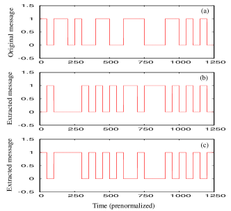
In this method, the return map constructed from the modulated driving signal is identical with the return map in Fig. 1, since we have again used (as in the case of single-step parameter modulation) the values and for while modulating the digital message in the transmitter. Eventhough one can assume different strips correspond to the different values of , it is now uncertain to assign a binary bit to a particular strip in the return map. This uncertainty is due to the fact that both the values of , namely, and have been used in transmitting each state of the binary bits, either ‘0’ or ‘1’ at various intervals of time. As a result, the points () calculated from the modulated driving signal fall on both the strips in all the segments of the return map while transmitting either the binary state ‘0’ or the binary state ‘1’. Thus, it is not possible to extract the original message from the return map unless one knows the rules by which the values of are switched for transmitting the digital information. As in the case of single-step parameter modulation, if one assumes that the strips closer to the origin corresponds to ‘0’ bit and the strips away from the origin corresponds to ‘1’ bit or vice versa [Li et al, 2006], then it is possible to obtain two different messages as shown in Fig. 3. From this figure, it is observed that the probability of extracting the original message from the return map is practically negligible. Hence, the controlled single-step parameter modulation is secure against the return map attack.
V.2 Plaintext Attack
If there is a chance of finding the values of which have been used in the transmitting chaotic system from the return map, an intruder can construct the subsystems identical to the receiver subsystems and they can be driven by the modulated driving signal . Eventhough it is almost impossible, still there is a chance to find the rules by which the parameter modulation is controlled with the help of known plaintexts and the synchronization of intruder’s subsystems with transmitting chaotic system. However, even this possibility can be eliminated if we use complicated functions or time-varying functions of and (collected at various instants of time) for controlling the parameter modulation. So, the controlled single-step parameter modulation appears to be reasonably secure even against the plaintext attack.
VI Controlled Multistep Parameter Modulation
To illustrate the controlled multistep parameter modulation, we again consider the Lorenz system with a set of values of parameters used in Sec. III and a modulation step of . Unlike the case of standard multistep parameter modulation, now the digital message ‘’ is transmitted with one of the values of the modulation parameter in the set {}, and ‘’ is transmitted with one of the values of from the set {}, when is positive. On the other hand, if is negative, the set of values {} is used for the modulation while sending ‘’ bits in the digital message and the set of values {} is used in the modulation for sending ‘’ bits in the message. It may be noted that all the values of have been used for transmitting each state, that is, either ‘’ or ‘’ of the digital message.
The transmission is done as follows. Suppose we have the bit ‘’ in the digital message to start with, then it is transmitted by assigning 3.1 to the modulation parameter . If the next bit is ‘’, it is then modulated using if is greater than zero, or using if is less than zero. On the other hand, if the second bit is ‘’, then the modulation is done using if is greater than zero, or it is done using , if is less than zero. This process continues upto and in each set of values of the modulation parameter and then it is reset to and in the respective sets. Thus, we have used all the values () of in transmitting each state of the binary message.
In the receiver end, there are subsystems driven by the modulated driving signal , each one with different values of from the set {}. Since one of these values is used at the transmitter end while transmitting the digital message, synchronization between the transmitting chaotic system and one of the receiver subsystems is always achieved. Hence, it is possible to obtain in the receiver end, from the synchronized subsystem where at any instant of time after transient die down. As the nature of control on the parameter modulation is known at the receiver end, the message can be constructed from the modulated driving signal by finding which of the subsystems in the receiver is synchronized with the transmitting chaotic system, once is obtained.
VI.1 Return Map Attack
Now, the return map constructed from the modulated driving signal is identical with the return map in Fig. 2, since we have again used (as in the case of multistep parameter modulation) the values from the {} for while modulating the digital message in the transmitter. Eventhough one can assume different strips correspond to the different values of , it is not possible to assign a binary bit to a particular strip in the return map. Because, now all the values of have been used in transmitting each state of the binary bits, either ‘0’ or ‘1’ at various interval of time. As a result, the points () calculated from the modulated driving signal fall on all the strips of a segment in the return map while transmitting either the binary state ‘0’ or the binary state ‘1’. Thus, it is not possible to extract the original message from the return map unless one knows the means by which the values of are switched for transmitting the digital information. Suppose the attacker randomly assume the binary state 0/1 to each strip in the return map, then it is possible to construct different messages, that is, different messages can be constructed for . In general, none of the messages will resemble the original message. Thus, there is practically negligible chance for obtaining the exact message from the return map provided the message is long enough.
VI.2 Plaintext Attack
As in the case of the controlled single-step parameter modulation, controlled multistep parameter modulation is secure against the plaintext attack if one uses the functions or time-varying functions of and (collected at various instants of time) for controlling the parameter modulation.
VII Conclusion
We have proposed a controlled parameter modulation technique (applicable to both the single-step and multistep parameter modulations) wherein parameter modulation is controlled by a chaotic signal (other than the driving signal) produced in the transmitter. These modified methods have been illustrated for the Lorenz system. Also, it has been shown that the controlled single-step parameter modulation and controlled multistep parameter modulation techniques are secure enough against both the ciphertext and plaintext attacks.
Acknowledgements.
This work has been supported by the National Board for Higher Mathematics, Department of Atomic Energy, Government of India and the Department of Science and Technology, Government of India through research projects.REFERENCES
-
Baptista, M. [1998] “Cryptography with chaos” Phys. Lett. A240, 50-54.
-
Bowong, S. [2004] “Stability analysis for the synchronization of chaotic systems with different order: application to secure communications” Phys. Lett. A326, 102-113.
-
Chee, C. Y. & Xu, D. [2006] “Chaotic encryption using discrete-time synchronous chaos” Phys. Lett. A348, 284-292.
-
Chua, L.O., Kocarev, Lj., Eckert, K. & Itoh, M. [1992] “ Experimental chaos synchronization in Chua’s circuit” Int. J. Bifurcation and Chaos 2, 705-708.
-
Cuomo, K.M. & Oppenheim, A. V. [1993] “Circuit implementation of synchronized chaos with application to communication” Phys. Rev. Lett. 71, 65-68.
-
Hayes, S., Grebogi, C. & Ott, E. [1993] “Communicating with chaos” Phys. Rev. Lett. 70, 3031-3035.
-
He, R. & Vaidya, P. G. [1998] “Implementation of chaotic cryptography with chaotic synchronization” Phys. Rev. E57, 1532-1535.
-
Hua, C. Yang, B. Ouyang, G & Guan, X. [2005] “A new chaotic secure communication scheme” Phys. Lett. A342, 305-308.
-
Kocarev, L. & Parlitz, U. [1995] “General approach for chaotic synchronization with applications to communication” Phys. Rev. Lett. 74, 5028-5031.
-
Kocarev, L. Sterjev, M. Fekete, A & Vattay, G. [2004] “Public-key encryption with chaos” Chaos 14, 1078-1082.
-
Lakshmanan, M. & Murali, K. [1996] Chaos in Nonlinear Oscillators: Controlling and Synchronization (World Scientific, Singapore).
-
Li, S. Álvarez, G. & Chen, G. [2006] “Return-Map Cryptanalysis Revisited” Int. J. of Bifurcation and Chaos 16.
-
Madan, R. N., [1993] Chua’s circuit: A Paradigm for Chaos (World Scientific, Singapore).
-
Mensour, B. & Longtin, A. [1998] “Synchronization of delay-differential equations with application to private communication” Phys. Lett. A244, 59-70.
-
Minai, A. A. & Pandian, T. D. [1998] “Communicating with noise: How chaos and noise combine to generate secure encryption keys” Chaos 8, 621-628.
-
Murali, K. & Lakshmanan, M. [1993a] “Transmission of signals by synchronization in a chaotic van der pol-duffing oscillator” Phys. Rev. E48, R1624-1626
-
Murali, K. & Lakshmanan, M. [1993b] “Synchroning chaos in driven chua’s circuit” Int. J. Bifurcations Chaos 3, 1057-1066.
-
Murali, K. & Lakshmanan, M. [1998] “Secure communication using a compound signal from generalized synchronizable chaotic systems” Phys. Lett. A241, 303-310.
-
Palaniyandi, P & Lakshmanan, L. [2001] “Secure digital signal transmission by multistep parameter modulation and alternative driving of transmitter variables” Int. J. of Bifurcation and Chaos 7, 2031-2036.
-
Pecora, L. M. & Carroll, T. L. [1990] “Synchronization in chaotic systems” Phys. Rev. Lett. 64, 821-823 (1990);
-
Pecora, L. M. & Carroll, T. L. [1991] “Driving systems with chaotic signals” Phys. Rev. A44, 2374-2383.
-
Pérez, G. & Cerdeira, H.A. [1995] “Extracting messages masked by chaos” Phys. Rev. Lett. 74, 1970-1973.
-
Short, K. M. [1994] “Steps toward unmasking secure communications” Int. J. of Bifurcation and Chaos 4, 959-977.
-
Short, K. M. [1996] “Unmasking a modulated chaotic communications scheme” Int. J. of Bifurcation and Chaos 6, 367-375.
-
Short, K. M. [1997] “Signal extraction from chaotic communications” Int. J. of Bifurcation and Chaos 7, 1579-1597.
-
Short, K. M. & Parker, A. T. [1998] “Unmasking a hyperchaotic communication scheme” Phys. Rev. E58, 1159-1162.
-
Wong, K. Ho, S. & Yung, C. [2003] “A chaotic cryptography scheme for generating short ciphertext” Phys. Lett. A310, 67-73.
-
Zhang, Y., Dai, M., Hua, Y., Ni, W, & Du, G. [1998] “Digital communication by active-passive-decomposition synchronization in hyperchaotic systems” Phys. Rev. E58, 3022-3027.