Counterpropagating dipole-mode vector soliton
Jochen Schröder and Philip Jander and Cornelia Denz
Institute of Applied Physics, Westfälische
Wilhelms-Universität Münster,
D-48149 Münster,
Germany
Tobias Richter and Kristian Motzek and Friedemann Kaiser
Institute of Applied Physics, Darmstadt University of
Technology,
D-64289 Darmstadt, Germany
Abstract
We experimentally observe a counterpropagating dipole-mode vector soliton in a photorefractive SBN:60Ce crystal. We investigate the transient formation dynamics and show that the formation process differs significantly from the copropagating geometry. The experimental results are compared with fully anisotropic numerical simulations which show good qualitative agreement.
OCIS codes: 190.5530,190.5330
Spatial optical solitons in a counterpropagating (CP) geometry have been proposed some time ago [1]. It has not been until recently however, that they have drawn wider attention [2, 3, 4, 5] and were investigated theoretically in saturable Kerr and local photorefractive media in one transverse dimension (1D). In addition, Cohen et al. experimentally demonstrated the existence of stable CP solitons with narrow stripe beams [3].
In a previous publication, we numerically predicted the existence of stable two-dimensional higher-order counterpropagating vector solitons in saturable Kerr media [6], commonly used as an approximation for the photorefractive nonlinearity. In the present paper we will experimentally and numerically demonstrate the existence of a counterpropagating dipole-mode vector soliton in a photorefractive SBN:60Ce crystal and investigate the transient formation dynamics.
A dipole-mode vector soliton consists of two mutually incoherent beams: an optical dipole and a fundamental-mode(FM) beam. The individually propagating dipole does not form a spatial soliton due to repulsion of the dipole components [7, 8]. However, if an FM beam which is incoherent to the dipole is launched in between the dipole components, they will be “trapped” via incoherent attraction [9, 7].
The counterpropagating geometry poses some additional challenges to the experimental setup. A soliton propagating inside a photorefractive crystal will be displaced in the positive direction of the crystal -axis. This effect is well-known as the so-called “beam-bending”-effect caused by charge-carrier diffusion. This effect has been extensively investigated in the case of single soliton formation. For the case of interaction copropating solitons or copropagating vector solitons, the effect does not change the fundamental interaction behaviour as the beams are displaced by the same amount [11]. Two counterpropagating solitons however are bend in the same direction. Thus when launched in a head-on configuration they will cross inside the crystal, resulting in a change of the soliton interaction length. Therefore, beam-bending has a significant effect on the transient formation dynamics as will become apparent later. Although at a first, rough glance the counterpropagating geometry might be very similar to configurations for e.g. double phaseconjugate (DPC) mirrors, the actual experiments are quite distinct. Both interacting beams are mutually incoherent, thereby not interfering in the material. The lack of an interference grating is obvious due to the insensitivity of the beams to slight angular changes once the solitons are formed. This effect can directly be seen when observing the dynamics of the soliton formation. In contrast, the existence of a grating would result in a highly selective Bragg-condition. Such a behaviour is typical for double phase conjugation configurations, but does not appear in our case. Moreover, the scales are much smaller than for DPC experiments (input beams are in the range of 20 micrometers, interaction angles are smaller than ), and effects that are typically associated with four-wave mixing and phase-conjugation do not appear on that scale. Nevertheless, in all our experiments we checked thoroughly that the effects we are observing are indeed caused by counterpropagating solitons.
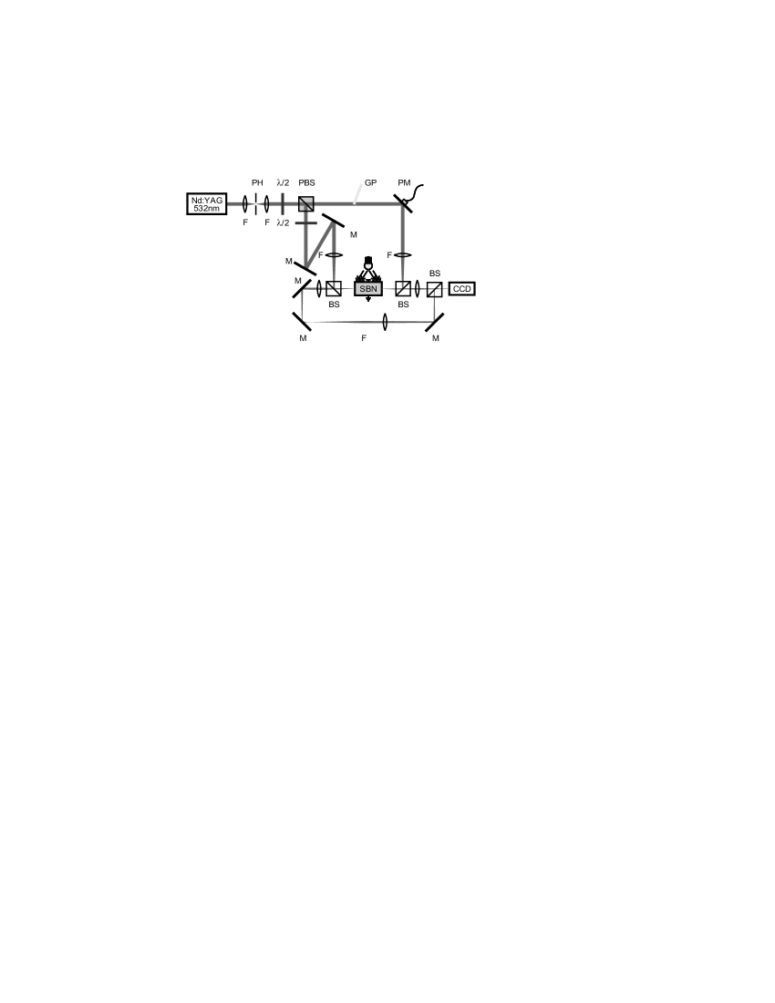
The experimental setup is depicted in Fig. 1. A frequency-doubled Nd:YAG-laser beam is divided into two arms. The beams are rendered mutually incoherent by a means of a piezo-driven mirror (PM) oscillating much faster than the response time of the crystal and are then focused onto the two faces of the photorefractive SBN-crystal via two beamsplitters. Due to the mutual incoherence of the beams, they do not interfere in the material nor produce an interference grating, thereby only interacting via their common phase modulation and induced refractive index channel. The crystal is biased with an external DC field along the -axis parallel to the crystallographic -axis. To take advantage of the large electro-optic coefficient of SBN, the beams are polarized along the same direction. Background illumination is realized with a white light source, which allows adjustment of the dark-intensity. To be able to observe the two crystal faces simultaneously, both are imaged onto the same CCD-camera. The optical dipole is generated by entering a tilted glass-plate into one of the arms, a well-known technique for the creation of optical dipoles, and is oriented perpendicular to the c-axis to minimize effects of the photorefractive anisotropy[10]. In order to compensate for the above-mentioned beam-bending, the beams are launched into the crystal in such a way that the input face of one beam coincides with the exit face of the counterpropagating beam propagating as an individual soliton. This results in a small angle () between the two incident beams. The power of the FM beam is and the power of the dipole . The approximate diameter of the beams at the input face is FWHM. The geometry of the SBN crystal is and propagation is along the -axis of the crystal for maximum propagation length, corresponding to approximately 4 diffraction lengths. The external field was set to and the background-illumination was adjusted in order to allow stable self-focusing and soliton formation of the individually propagating FM beam.
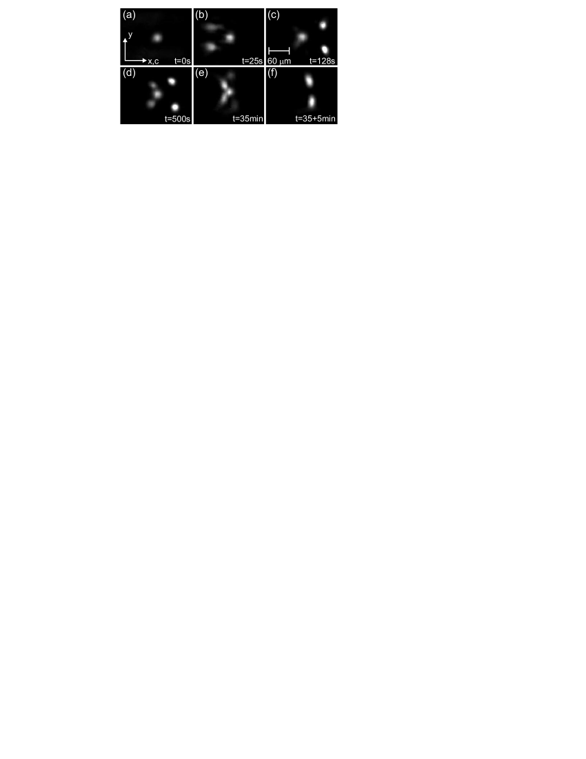
The formation of the dipole-mode vector soliton is shown in Fig. 2. The images are taken at the exit face of the dipole beam, the less intense spot in the middle of the images is the reflection of the FM input at the crystal face. It serves as a reference and does not influence the soliton formation process. When the nonlinearity is turned on, the dipole initially self-focuses to the left of the FM beam (Image (b)). This is due to the initial angle between the beams. The dipole is then strongly deflected to the right, as beam-bending and attraction from the FM soliton act in the same direction. The dipole splits up and two spots of low intensity with a much smaller separation appear on the left side of the FM beam (c). As time elapses, this trapped part of the dipole draws intensity from the non-trapped part and the non-trapped part is attracted horizontally toward the FM input (d). After approximately 35 minutes, the system reaches equilibrium, with almost all power of the dipole trapped (e). When the FM beam is blocked, the dipole components quickly repel and move to the right due to beam-bending. Image (f) shows the dipole after propagating individually for approximately 5 minutes. The separation of the dipole components of the trapped and non-trapped part in image (e) was and respectively, compared to for the individually propagting dipole.
The transient formation dynamics differ significantly from the copropagating case, which makes them particularly interesting. The most striking fact is the splitting of the dipole into two parts, which is not observed in the copropagating geometry. Although at a quick glance such an effect might be attributed to phenomena as conical scattering, a thourough analysis shows immediately that those effects can be excluded: the two interacting solitons are mutually incoherent, and thereby not able to interfere with each other. Moreover, the angles at which these new beams appear are in the range of one degree, much smaller than the scattering cone which should be well above . Instead, the splitting can be explained by the angle between the beams which is introduced to compensate effects of beam-bending. Soliton formation in photorefractive crystals is a two-step process, in which the beam self-focuses initially and is then displaced by beam-bending [11]. After self-focusing of the counterpropagating beams self-focus but before beam-bending takes place, the beams only cross at one point inside the crystal due to the angular adjustment. At this point the colliding beams will interact strongly, which causes the observed splitting. The non-trapped part of the dipole is then deflected by the combined forces of beam-bending and incoherent attraction of the dipole, causing the dipole to “overshoot”. This explains why the non-trapped dipole part is initially displaced further then the individually propagating dipole, which can be seen by comparing images (c) and (d) with image (f) in Fig. 2. The second remarkable feature of the counterpropagating dipole is the long timescale of the formation process. It differs significantly from copropagating solitons, with formation times in the range of seconds or even shorter for higher intensities[11], compared to around 30 minutes for the counterpropagating dipole-mode vector soliton to reach a stable state for similar parameters.

As can be seen from Fig. 2(c)-(e), the trapped dipole is not aligned with the input of the counterpropagating beam, but is displaced slightly to the left. The output of the FM beam, which can be seen in Fig. 3 shows a similar picture. The FM soliton is displaced to the left of the dipole input. This is in agreement with earlier simulations [6] which predict a threshold propagation length where the symmetry along the dipole axis is broken. Thus our experimental results are above this threshold length. Additionally we observe that the the FM beam splits as well. Fig. 3(b) shows the exit face of the FM beam when the dipole is shortly blocked. A fraction of the beam has split from the main part and has coupled into the dipole waveguide.
To verify our experimental results, we carried out simulations in the anisotropic, nonlocal model [12]. The two counterpropagating beams are denoted by their slowly varying envelopes and . The total optical field can then be written as , with being the wavevector in the undisturbed crystal. Since we are considering and to be mutually incoherent, the total intensity is just given by . The Kukhtarev model of the photorefractive crystal leads under simplifying but well justified assumptions to the following equation
| (1) |
for the potential of the electrical screening field, which causes the nonlinear change of the refractive index via the Pockels effect. denotes the externally applied electrical field, is the diffusive coupling strength, is the effective time constant of the crystal, and is measured in units of the background intensity.
The propagation of the beams is in paraxial approximation described by the set of equations
| (2a) | ||||
| (2b) | ||||
with the nonlinear coupling constant , which contains the refractive index of the unperturbed crystal , the effective element of the electro-optic tensor , and the transverse scaling constant . denotes the transverse Laplacian. The propagation (-)axis is scaled to the diffraction length . The values used in the simulations are (typical beam widths are about ), , , , and with . The total propagation distance was chosen to be (11.1 mm).
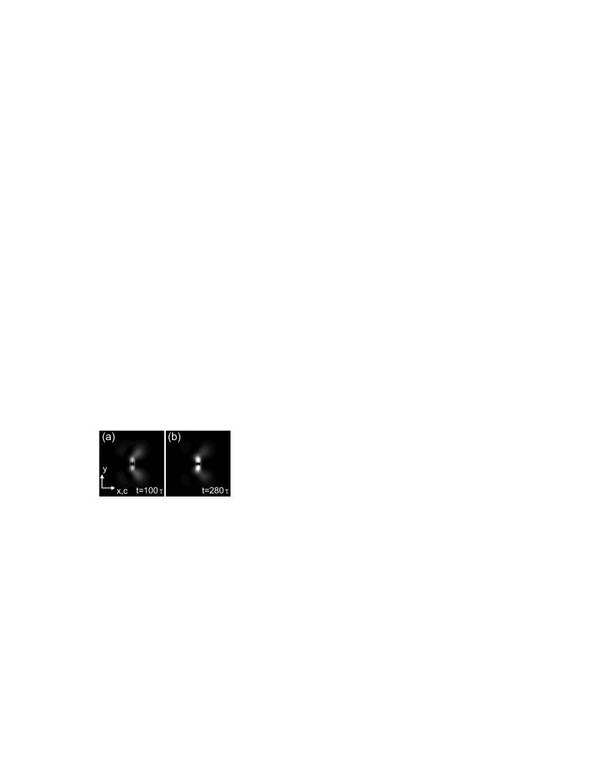
The results of the simulations are shown in Fig. 4. Image (a) and (b) show the exit face of the dipole beam at times and after the start of the simulation. Although the numerical and experimental results differ in detail, the main features of the interaction are very similar. The splitting of the dipole into a trapped and non-trapped part can clearly be observed in Fig. 4(a), although it is not as pronounced as in the experiment. As time elapses the trapped part grows in intensity drawing energy from the non-trapped part (Fig. 4(b)). The second main feature, the exceptionally long timescale is reproduced as well, with the time constant corresponding to approximately .
To summarize, we have shown the existence of a stable counterpropagating dipole-mode vector soliton in a photorefractive SBN crystal. The vector soliton differs considerably in many aspects from its counterpart in copropagating geometry. The timescale of the transient dynamics are significantly larger. During the formation the beams split up, and a trapped and non-trapped part of the dipole can be observed.
References
- [1] M. Haelterman, A. P. Sheppard, and A. W. Snyder, Opt. Comm. 103, 145 (1993).
- [2] O. Cohen, R. Uzdin, T. Carmon, J.W. Fleischer, M. Segev, and S. Odoulov, Phys. Rev. Lett. 89, 133,901 (2002).
- [3] O. Cohen, S. Lan, T. Carmon, J.A. Giordmaine, and M. Segev, Opt. Lett. 27, 2013 (2002).
- [4] C. Rotschild, O. Cohen, O. Manela, T. Carmon, and M. Segev, J. Opt. Soc. Am. B 21, 1354 (2004).
- [5] M. Belić, P. Jander, A. Strinić, A. Desyatnikov, and C. Denz, Phys. Rev. E 68, 25,601 (2003).
- [6] K. Motzek, P. Jander, A. Desyatnikov, M. Belić, C. Denz, and F. Kaiser, Phys. Rev. E 68, 066,611 (2003).
- [7] W. Królikowski, E. A. Ostrovskaya, C. Weilnau, M. Geisser, G. McCarthy, Y. S. Kivshar, C. Denz and B. Luther-Davies Phys. Rev. Lett. 85, 1424 (2000).
- [8] T. Carmon, C. Anastassiou, S. Lan, D. Kip, Z.H. Musslimani and M. Segev, Opt. Lett. 25, 1113 (2000).
- [9] J.J. Garcia-Ripoll, V.M. Perez-Garcia, E.A. Ostrovskaya, and Y.S. Kivshar, Phys. Rev. Lett. 85, 82 (2000).
- [10] W. Królikowski, B. Luther-Davies, C. Denz, J. Petter, C. Weilnau, A. Stepken and M. R. Belić Appl. Phys. B 68, 975 (1999).
- [11] C. Denz, W. Królikowski, J. Petter, C. Weilnau, T. Tschudi, M.R. Belić, F. Kaiser, and A. Stepken, Phys. Rev. E 60, 6222 (1999).
- [12] A.A. Zozulya and D.Z. Anderson, Phys. Rev. A 51, 1520 (1995).