The Phase Information Associated to Synchronized Electronic Fireflies
Abstract
An electronic implementation referring to fireflies ensembles flashing in synchrony in a self-organization mode, shows the details of the phase-locking mechanism and how the phases between the electronic oscillators are related to their common period. Quantitative measurements of the timing signals link the limits of a steadily established synchronization to the physics of the electronic circuit. Preliminary observations suggest the existence of bifurcation-like phenomena.
pacs:
05.45.Xt, 85.60.Bt, 89.75.-kI Introduction
Self-organization is a widespread feature appearing under a variety of living and inanimate systems. Synchronization that can be understood as an adjustment of rhythms of oscillating objects due to their weak interaction PIKOVSKY , represents one of the forms of self-organized matter BLEKHMAN .
There are numerous examples of systems of coupled oscillators able to induce structured behaviors between the interacting oscillators MIROLLO-STROGATZ ; STROGATZ ; WINFUL ; WIESENFELD ; HOHL .
The synchronized flashes of huge ensembles of fireflies in south-asian countries swarm trees is one of these surprising self-organization effects. The phenomenon was already mentioned three centuries ago by the Dutch physician Kaempfer in 1727 BUCK-BUCK3 , but it is only recently that experimental (see e.g. BUCK ; BUCK-BUCK1 ; BUCK-BUCK2 ; LLOYD1 ; LLOYD2 ; MOISEFF-COPELAND ) and theoretical ERMENTROUT ; MIROLLO-STROGATZ researches suggested an adequate operational model CAMAZINE .
At the individual firefly level, the rhythm of the recurring flashes is supposed to be under the control of a neural center which itself may be optically influenced by the flashes of neighboring fireflies. From an experimental point of view, it is clear that the fireflies interact and modify each other’s rhythms, which automatically leads to the acquisition of synchrony.
Although the anatomical details of the neural activity are largely unknown, a model has been proposed which accounts for the essential operational parameters. The model is based on a relaxation oscillator in which it is possible to reset the duty cycle by optical means. Moreover, the reset action is phase dependent: the duty cycle is lengthened or shortened depending of the time interval between the flashes of the interacting fireflies.
By constructing an electronic implementation of it, Garver and Moss showed that the model worked as it was supposed to do GARVER-MOSS . They report ensemble behaviors which indeed are analogous to what is observed with fireflies, although they experimented on a much smaller scale.
We constructed an “open” version of this electronic firefly, whose free-run duty cycle can be modified and adjusted manually on the spot, and on which quantitative measurements of periods and phase differences may be performed with the required precision. We call it “LCO” the acronym of Light Controlled Oscillator.
Compared to a firefly, the workings of an LCO are without any mystery, which allows for a detailed quantitative description of the synchronization mechanism at least for small ensembles.
Our aim is to experiment with LCO’s and to investigate the local level features of the self-organization they exhibit. At first we are looking for the parameters involved in a steady synchronization state achieved by two LCO’s, bringing out the factors leading to synchrony. It appears that the period of synchronized LCO’s is tightly related to the phase difference between them, showing how the electronics of the synchronization actually works, and why synchrony acquisition ceases outside limits set by the physics of the system. Similar phases relationships have been found for systems of three LCO’s and more, revealing interesting features.
II Presentation of an LCO
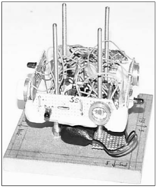
Basically, our LCO (Fig. 1) is composed of a LM555 circuit wired as an astable LM555 , the alternations of which are determined by a dual RC circuit in parallel with four photo-sensors GARVER-MOSS .
We made nine LCO’s (Fig. 2): nine autonomous oscillators coupled by their IR beams. They had much success when, disposed on a table, they went to synchronize like exotic fireflies which they are aimed to mimic. Each LCO is a module made of the same electronic components and having the same structure. A square base (11 cm 11 cm) gives the over-all horizontal dimensions of each LCO in the global pattern. With nine LCO’s it is possible to achieve several different patterns.
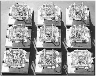
Each base may sustain several printed circuits giving the possibility of vertical extension, but keeping the same over-all horizontal dimensions.
For the time being, our LCO’s have two levels (Fig. 1). The lower part consists of a 9 volt battery and its clamping system. The oscillator’s printed circuit with the variable resistors allowing the adjustment of the period’s two time intervals, makes the upper part of a LCO module. The circuit is square-like too but its size is smaller than the basis. Even smaller printed circuits bearing each an infrared LED and a photo-sensor, are fixed vertically on the sides of the upper part. Provision is made to mask the sensors allowing the LCO’s to oscillate ”in the dark”. In the aim of public presentations, the upper part bears a fifth LED flashing visible light in synchrony with the IR one’s, just to produce a “firefly effect”.
The RC timing components of the LM555 consist of two resistors and a single capacitor (Fig. 3). Let , and be the values of those components responsible for the LCO’s timing with masked photo-sensors (timing “in the dark”).
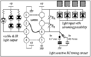
The period is made up of two states: a longer one that may be changed by manually adjusting , a shorter one that may be changed by acting on . The LED’s are wired at the output of the LM555, switching on during the shorter part of the period.
The photo-sensors act as current sources when they are receiving light, shortening the charging time of the capacitor and making longer the time required to discharge it.
In our model the resistors and are partially variable
We use the same LCO’s for two different missions: firstly, for demonstrations where it is required to carry out synchronization at a pace of about one flash per second (very impressive), and secondly for observing the synchronization by an oscilloscope, which requires a period of about 30 ms. This change of period range is made by modifying nothing else but the capacitor value, which has the advantage of leaving the lighting percentage per period unchanged (less than 2%) because the ratio is not modified:
As the illumination of the photo-sensors modifies the period of an LCO, it is useful to distinguish the functioning of it in the dark from its functioning when receiving light pulses from its neighbors or diffuse light from the surroundings.
When all the photo-sensors of an LCO are masked, its period depends only from its electronics. We took this particular period as a reference for each LCO.
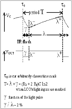
In the framework of this article, we use the following parameters related to the synchronization of the LCO (Fig. 4):
-
•
, the larger alternation time, it corresponds with a capacitor’s charging time between and of the total charge.
-
•
, the shorter alternation time, it corresponds with a capacitor’s discharging time within the same limits.
-
•
, the beginning and the end of a long alternation.
-
•
, the instant coinciding with the transition from to ; here after we will use this parameter as the “reference moment” in the period of an LCO.
-
•
, the common period of a set of synchronized LCO’s.
-
•
, the periods, the “reference moments”, and the duration of the alternations of LCOA, LCOB, in illumination situations.
-
•
, the periods and the durations of the short and long alternations “in the dark” of LCOA, LCOB, LCOC, i.e. when all their photo-sensors are masked.
III An LCO coupled to a short pulse blind LCO
In order to investigate the mechanisms inducing the synchronization, we have placed an LCO, namely LCOB, in interaction with the equivalent of an LCO “kept in the dark”.
Let LCOA be this blind LCO; its IR pulse (lasting during ) has been reduced to a quarter of . In practice it is obtained from a low frequency generator controlling a monostable producing a pulse of constant duration and sufficiently short.
The signals are picked up at the low impedance output of the LM555; the measurements of phases and periods are carried out with an oscilloscope Tektronix TDS 3012 according to well-known procedures; observations are done without difficulty with a precision of about 0,1%. To be coherent with the measurements presented further on in this article, the triggering is provided by the LCOA considered as the reference LCO.
From the very first observation it is obvious that the synchronization implies a phase relation between the two oscillators.
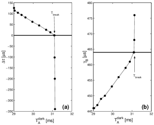
Fig. 5(a) represents (i.e. the position of related to , the latter being taken as reference) as a function of the period of the blind LCOA.
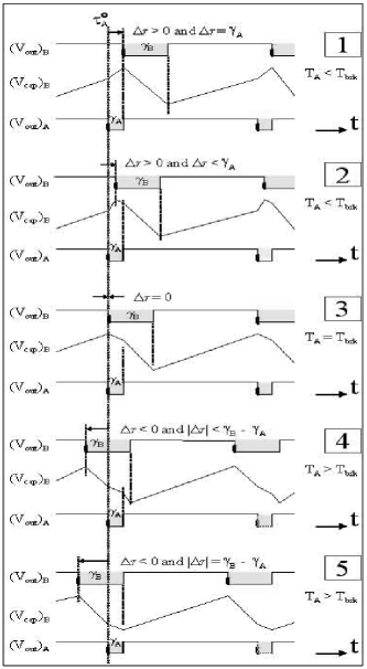
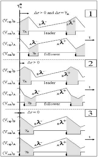
When , i.e. when appears before (Fig. 6 cases 1 and 2), the phase-control is stable and can be measured easily. However, for (Fig. 6 cases 4 and 5), the stability is much more precarious, even if also in that situation there is a synchronization of LCOB to the blind LCOA.
The shape of as a function of can be fairly well schematized by two straight lines intersecting at for the abscissa .
The plot suggests two phase-control modes, situated at either side of (Fig. 6, case 3), distinguishing themselves by two parameters which are easy to measure:
-
-
The domain of the phase-locking, that is to say the interval limited by the periods for which there is synchronization.
-
-
The slope of the straight lines, which represents somehow the gain of a servo-system’s feedback control.
These two modes correspond to different control mechanisms:
-
•
For , there can be only widening of the period because the illumination and thus the photo-current are totally included in the interval (Fig. 6 cases 4 and 5), under these circumstances the photo-current adds to the discharging current of the capacitor through . As the extension of corresponds with an increase of the period, the phase-control is stable. Nevertheless the influence of the photo-current on the extension of the period is of little importance, first because the discharge current is by two orders of magnitude superior to the charge current, and secondly because represents only 2% of the period. The upper limit of the phase-locking is reached as soon as the photo-current shortens the alternation of the following period, that is to say as soon as the positive feedback resulting from this situation makes the phase-control unstable.
-
•
For , Only a shortening of the free-run period is possible. The shortening takes place during the end of the interval , by increasing the charging speed of capacitor due to the photo-current brought in, in parallel with . Due to the photo-current, the voltage of reaches more rapidly the value which triggers the switching from the alternation towards the alternation. The lower limit of the phase-locking domain is reached when the duration (Fig. 6, case 1) during which the photo-current speeds up the charging of the capacitor, is not sufficient anymore to reach the switching point of towards . As a consequence, for the shortest periods, the synchronization depends strongly on the intensity of the light received by phase-locked LCOB.
-
•
For , This constitutes the intermediate situations (Fig. 6, case 2): the excess of photo-current acts in accordance with the mode already described, achieving a not so important lengthening of the synchronized period as compared to its shortening.
IV An LCO coupled to a blind LCO flashing large pulses
The experimental setup that has been used to get Fig. 7, differs from the previous one, only by the width of the flashes emitted by the blind LCO: they have been widened to increase the ratio from to 2, allowing the blind LCO flashes to overlap the synchronized LCO flashes.
The observation of this second type of synchronization is important because it looks more like that of an actual LCO pair in mutual interaction, for which differences between the alternations are the rule with occurrences of overlapping.
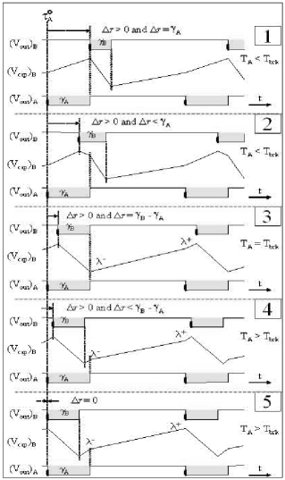
In the phase-locking with short pulses ( ratio) one distinguishes five unambiguous situations of synchronization. However, when the alternation is significantly larger than , it is possible that it overrides by illuminating the end and the beginning of the neighboring intervals of (Fig. 8, case 4).
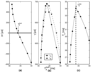
The graphs and as a function of in Figs. 7(a) and (b), show a singular value for which there is a change of slope.
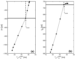
corresponds to a situation in which covers completely and is about to start the covering of (the start of the following interval (Fig. 8, case 3).
We observe that :
- a)
-
b)
For , the interval covers three alternations of LCOB (Fig. 8, case 4) and the phase-control functions differently:
- In Fig. 7(a)
-
: is constant because it remains entirely covered by ; however is sufficiently large to illuminate either sides of , that is to say to ensure the phase-control by truncating (the end of alternation ) while at the same time shortening ) the beginning of the following .
- In Fig. 7(b)
-
: varies more slowly indicating a change of phase-control mode, indeed the increase of the period results from the combination of a constant extension of and of a shortening of the two neighboring alternations and .
Finally, Fig. 7(a) shows that the upper limit of the synchronization domain is reached when (Fig. 8, case 5), i.e. when the time-marks and are superposed. This observation is of major importance for the analysis of the mutual synchronization between two interacting LCO’s , neither being blind. Indeed the loss of synchronization at , means that shortening at the start of a alternation is not sufficient to maintain the phase-control, the latter working only when it is the end of which is truncated, i.e. .
V Synchronization between two interacting LCO’s. Measure and analysis
When two interacting LCO’s synchronize, their short alternations and cover each other mutually, including their time-mark and . As a consequence, the fractions of the alternations and which are not superposed illuminate the preceding and the following (Fig. 10, case 2 and its symmetrical case which is not represented).
This situation is similar to that described at the end of the preceding paragraph (Fig. 8, case 4 and 5); it allows us to deduce that of the two parts, and of an alternation , it is only that controls the synchronization in a decisive way. Indeed (Fig. 8, case 5) shows that phase-locking and synchronization stops as soon as ceases to be illuminated.
The plots of , and , and , as a function of in Figs. 9(a), (b) and (c) show the binary structure of the interaction between two LCO’s: In Fig. 9(a), may be of two polarities in an equivalent way, indicating that the two LCO’s are interchangeable. In Fig. 9(b), the time intervals and change in the same manner when they are overlapping. When and are exactly superimposed, i.e. when (Fig. 10, case 3), their length is at a maximum as does the common period of the synchronized LCO’s (Fig. 9(c)).
On both sides of the maximum of , the light associated with the one or the other alternation truncates the corresponding (Fig. 10, case 1, 2, 4 and 5). As observed earlier, the photo-effect on is not as strong as on . In fact two interacting LCO’s have not the same status: one is a leader who cuts the part of his coupled partner, the latter being the follower who cuts the part of his leader. However this status may change, depending of the sign of , i.e. the relative positions of and .
VI Synchronization between several LCO’s
As long as the interacting system has a binary symmetry, the choice of the reference LCO is irrelevant and is without importance for the quantitative observation of the synchronization: the reference LCO is simply that one whose period is modified manually. On the opposite, for sets of more than two LCO’s it is mandatory to specify the position of the reference LCO in that of the interacting LCO’s.
We have been able to observe phase-locking in sets made up of 5 LCO’s, using two Tektronix TDS 3012 oscilloscopes triggered simultaneously by the output signal of the reference LCO. However those last measurements were rather difficult to perform, due to the intrinsic instability of the LM555 oscillators and/or the presence of multiple states.
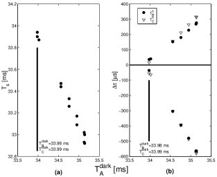
Fig. 11(a) and (b) have been obtained with a set of 3 LCO’s put in line: LCOB–LCOA–LCOC. The reference was LCO in the mid position. Synchronization has been achieved for varying between 33.98 ms and 35.2 ms. The “periods in darkness” of the other are: =33.98 ms and =33.99 ms.
Fig. 11(a) shows a bifurcation-like phenomenon: the 3-LCO system synchronizes according to two modes brought out by two significantly different values of as a function of .
Fig. 11(b) shows the same behavior by plotting the time-marks and as a function of , taking as the reference time-mark.
There is obviously a symmetry in this 3-LCO synchronization: once the LCO’s are synchronized, the phases may equally well have one or the other polarity (Fig. 11(b)). Moreover, a closer look at the data producing Fig. 11(b) shows that and are always of opposite polarity; this suggests that LCOB and LCOC are in some way interchangeable. However, before the synchronization has been settled, it is not possible to foresee the mutually exclusive polarities of and , confirming that a bifurcation-like phenomenon is present.
VII Conclusion
Obviously, synchronization is tightly linked to phase-locking and the domain associated with it. This is why we considered as a criterion that coupled LCO’s are synchronized only if they exhibit a stable dependency of their phase as a function of their period differences.
Our measurements show that LCO’s synchronize in as much that the phases involved in the phase-locking feedback do not exceed values related to the widths of the coupling light pulses.
Finally we suggest using the criterion associating synchronization and phase-locking domain as a test to compare theoretical models of interacting LCO’s to their experimental implementations. In a further publication, we analyze this situation.
References
- (1) A. Pikovsky, M. Rosenblum and J. Kurths, Synchronization a universal concept in nonlinear sciences (Cambridge University Press, Cambridge, 2001).
- (2) I. Blekhman, Synchronization in science and technology (Asme Press, New York, 1988).
- (3) Mirollo RE, Strogatz SH, Synchronization of pulse-coupled biological oscillators , SIAM Journal of Applied Mathematics 50 (1990) 1645-1662.
- (4) S.H. Strogatz, R.E.Mirollo and P.C. Matthews, Coupled nonlinear oscillators below the synchronization threshold: Relaxation by generalized Landau damping, Phys. Rev. Lett. 68 (1992) 2730–2733.
- (5) H.G. Winful and L. Rahman, Synchronized chaos and spatiotemporal chaos in arrays of coupled lasers, Phys. Rev. Lett.65 (1990) 1575–1578.
- (6) K. Wiesenfeld, P. Colet and S.H. Strogatz, Synchronization transitions in a disordered Josephson series array, Phys. Rev. Lett. 76 (1996) 404–407.
- (7) A. Hohl, A. Gavrielides, T. Erneux and V. Kovanis, Localized synchronizationin two coupled nonidentical semiconductor lasers, Phys. Rev. Lett. 78 (1997) 4745–4748.
- (8) J. Buck and E. Buck, Mechanism of rhythmic synchronous flashing of fireflies, Science 159 (1968) 1319–1327.
- (9) J. Buck, E. Buck, J.F. Case and F.E. Hanson, Control of flashing in fireflies. V. Pacemaker synchronization in Pteroptyx cribellata, J. Comp. Physiol. A 144 (1981) 287–298.
- (10) J. Buck and E. Buck, Synchronous fireflies, Sc. Am. 234 (1976) 74–85.
- (11) J. Buck, E. Buck, Toward a functional interpretation of synchronous flashing by fireflies, Am. Naturalist. 112 (1978) 471–492.
- (12) J.E. Lloyd, Fireflies of Melanesia: Bioluminiscence, mating behavior and synchronous flashing (Coleoptera: Lampyridae), Env. Entom. 2 (1973) 991–1008.
- (13) J.E. Lloyd, Model for the mating protocol of synchronously flashing fireflies, Nature 245 (1973) 268–270.
- (14) A. Moiseff and J. Copeland, A new type of synchronized flashing in a North America firefly, J. Ins. Behavior 13 (2000) 597–612.
- (15) G.B. Ermentrout, An adaptive model for synchrony in the firefly Pteroptyx malaccae J. Math. Biol. 29 (1991) 571–585.
- (16) S. Camazine, J.L. Deneubourg, S. Franks, J. Sneyd, G. Theraulaz and E. Bonabeau Self-organization in biological systems (Princeton University Press, Princeton, 2001).
- (17) Garver W, Moss F, Electronic fireflies, Sc. Am. 269 (1993) 128-130.
- (18) LINEAR Databook, (1982), LM555/LM555C Timer. National Semiconductor Corporation (9): 33-38.