[
From coherent to incoherent hexagonal patterns in semiconductor resonators
Abstract
We find that hexagonal structures forming in semiconductor resonators can range from coherent patterns to arrangements of loosely bound spatial solitons, which can be individually switched. Such incoherent arrangements are stabilized by gradient forces, as evidenced by the stability of hexagonal structures with single- or multiple-soliton defects. We interpret the experimental observations by numerical simulations based on a model for a large aperture semiconductor microresonator.
pacs:
PACS 42.65.Sf, 42.65.Pc, 47.54.+r] Pattern formation in the form of hexagonal structures was predicted years ago for resonators containing a reactive nonlinearity [1]. We have recently given the first proof of the phenomenon using semiconductor microresonators in the dispersive limit [2]. This kind of pattern formation was regarded as an important precursor of optical soliton formation, the latter being of technical importance for all-optical information processing [3]. We showed the existence of these bright and dark spatial solitons recently [4, 5].
Our finding, that individual bright spots of the hexagonal
patterns can for certain parameters be ”switched off” without
apparent effects for the rest of the hexagonal pattern
[2], caused a debate about whether such individually
switchable ”pixels” in a hexagonal pattern have soliton
properties and more in general about the nature of these
hexagonal patterns. In this article we clarify these questions
by interpreting our experimental observations using numerics on a
semiconductor resonator model [6].
For completeness we repeat shortly the experimental arrangement: Light of wavelength near the semiconductor band edge (850 nm), generated by a continuous Ti:Al203-laser, irradiates an area of 50-100 m diameter of the semiconductor resonator sample, with intensity of up to 3 kW/cm2 . The sample is a quantum-well stack between Bragg mirrors of 99.7 reflectivity [7]. The optical resonator length is about 3 m so that a Fresnel number of several 100 is excited, sufficient for complex structure to form. The light is admitted to the sample for durations of a few s (through a mechanical chopper, to limit thermal phenomena) repeated every ms.
As the substrate, on which the resonator sample is grown, is
opaque at the wavelength used, all observations are done in
reflection. Either by taking ns-snapshots of the illuminated
area, or by following the reflected intensity in particular
points of the illuminated area as a function of time, using a
fast photodiode. Details are given in [2, 5].
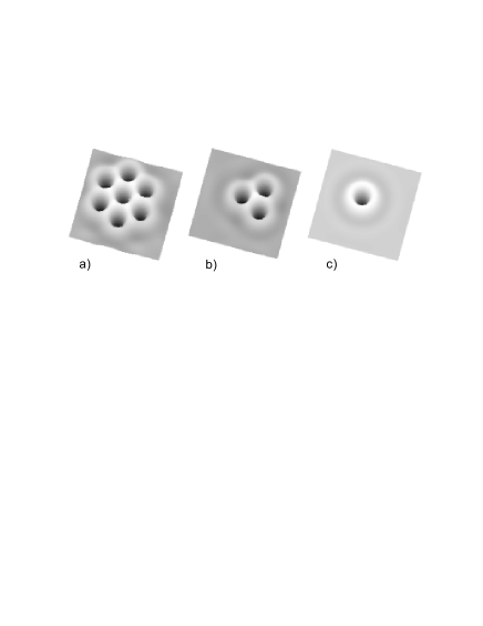
Fig. 1 shows structures observed at a wavelength of 880 nm (i.e. to a good approximation in the defocusing Kerr limit), for different illumination intensities and detunings of the light from the resonator resonance center. The half-width-half-maximum of the resonance is 0.1 nm. At a detuning of -0.1 nm, for lower intensities a hexagonal pattern of dark spots forms (Fig. 1a). This converts to a hexagonal pattern of bright spots for higher illumination (Fig. 1b).
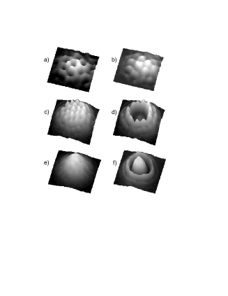
For -0.2 nm at lower intensity a bright hexagon forms (Fig. 1c). The smaller period at -0.2 nm compared to -0.1 nm indicates that these patterns are formed by the ”tilted-wave”-mechanism [8] as in most known cases of pattern formation in optical resonators [1, 9]. At -0.2 nm the resonator characteristic is already bistable so that the central part of the illuminated area is switched at a larger intensity as shown in Fig. 1d. The switched area is the central part of the Gaussian illumination beam in which the intensity exceeds the ”Maxwellian intensity” [10], the latter being the intensity at which the switching front surrounding the switched area does move neither radially inward, nor outward.
At -0.4 nm the structure is no longer visible (Fig. 1e). The pattern period at this large detuning is small enough to apparently be washed out by non-local effects like carrier diffusion. The switching of the central part at higher intensity then has the appearance of switching in an unstructured environment (the counterintuitive central intensity peak in case (f) compared with case (d) results due to the nonlinear resonance effect). We note the radial modulation outside the switched area, clearly apparent for the switched cases Figs 1d and 1f (the azimuthal modulation of the first ring in Fig. 1d is a residual of the hexagonal structure in Fig. 1c). This radial modulation is due to the ”oscillating tails” of the switching front [10] responsible for such phenomena as stabilization of solitons [10], forming bound states of several solitons (”molecules”) [11], or stabilizing large patterns (as shown below), through the forces associated with the gradients of the modulations [12].
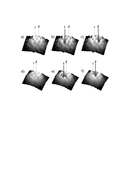
We note for clarity that the switching in the lower two rows of Fig. 1 is effected by increasing the intensity of the (Gaussian) illumination beam. As opposed to that in Fig. 2 switching is done by an additional more sharply focused beam (of perpendicular polarization, thus incoherent with the main illumination field). For the switching experiments the additional light, focused to a diameter of 8 m, comparable in size to the bright spots in the hexagonal patterns of Fig. 1 and Fig. 2, was aimed at particular ones of the bright spots in the hexagonal patterns in short pulses (10 ns).
Fig. 2 a, b, c shows two bright spots (marked 1 and 2) at which the switching light pulses were aimed. In this way pixel 1 is switched off in Fig. 2b while all other pixels of the hexagonal pattern remain unaffected. Likewise, aiming the switching pulse at pixel 2 switches this latter one off without affecting the rest of the pattern (Fig. 2c).
We recall that we speak here of switching in the strict sense: pixels 1 and 2 in Fig. 2b, 2c, respectively remain switched off, stationarily, after the end of the short (10 ns) switching pulse. It was also possible, as Figs 2 d, e, f show, to switch several pixels at once by using a higher intensity of the switching beam and aiming at a spot surrounded by 3 pixels. Figs 2 d, e, f show that different ”pixel-triples” can be switched when the switching beam is aimed at different locations.
The ”local switching” results of Fig. 2 suggest that the hexagonal patterns we observe are not necessarily ”coherent patterns” in the sense that a perturbation in one part of a pattern affects the entire pattern. Rather in Fig. 2 the hexagonal patterns appear to behave like a collection of loosely bound individual spatial solitons whose structure and stability is independent of the rest of the pattern. (And vise versa the rest of the pattern is unchanged if individual solitons are removed). On the other hand, for other parameters such as for Fig. 1 c, d, there are coherent patterns in which a local perturbation with focused address pulses aimed at different places leads to a destruction of the whole pattern.
In order to gain more insight into the stability/instability of the various structures we investigated numerically the model [6] for a large aperture semiconductor resonator, which we found in good agreement with experimental results recently [13, 14]. The set of equations for the intracavity field and the carrier density is:
| (1) |
where is the incident field, is the bistability parameter [6], and describe the absorptive and refractive nonlinearities, respectively. is the detuning of the optical field from the resonator resonance, is the ratio of the photon lifetime in the resonator to the nonradiative carrier recombination time, is the diffusion coefficient (normalized to the diffraction coefficient) and is the transverse Laplacian.
Fig. 3 shows the calculated resonator plane wave characteristic for a rather dispersive nonlinearity (Kerr-type, defocusing). We note that this characteristic is not usually stable (i.e. plane waves are not necessarily stable solutions). For a large detuning the lower branch is generally modulationally unstable (dashed line Fig. 3). At smaller intensity (Fig. 3a) a bright spot hexagon develops supercritically, whereas it becomes a dark spot hexagon at higher intensity (Fig. 3c,d). Transition to patterns at higher intensity is subcritical because existence ranges for stable structures overlap. The bright hexagons transform to the dark hexagons via a stripe pattern (Fig. 3b) formed at intermediate intensity.
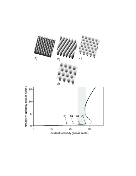
Dark/bright spots correspond to bright/dark spots in the experiment where observation is in reflection.
We note the different periods of the structures in Fig. 3. As can be seen, the pattern period is increased from a) to d) which translates into smaller wavefront tilt, indicating a smaller effective detuning, whereas the external resonator detuning is the same for all cases. The mechanism of importance here is ”nonlinear resonance” [15], i.e. the internal parameter of field and with it the nonlinear refraction adjust to reduce the detuning (and the wavefront tilt). Consequently, with the higher input intensity, for example in case d), the structure formation is of more nonlinear origin than in case c). In turn, case c) is of more nonlinear origin than cases b) and a). Thus the cases a) and c) represent patterns governed by the tilt of 6 plane phase-locked waves, the tilt being prescribed by the external parameter of resonator detuning. The case d) is not exclusively determined by this external parameter but the high nonlinearity gives the system more internal freedom and flexibility permitting larger numbers of stable patterns.
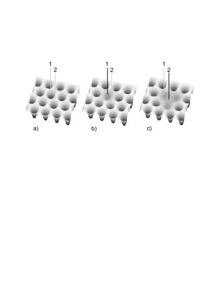
Numerical experiments show that this is indeed the case. Fig. 4 shows that it is possible to remove, as in the experiment, one dark spot, or three dark spots, from the patterns without destabilizing the rest of the structure. One sees in Fig. 4 b, c that at the locations of the removed solitons, the field is not uniform. The residual field nonuniformities are the result of the superposition of the ”oscillating tails” surrounding all dark spots. For the case Fig. 3d, one could therefore picture the structure as a weakly bound collection of dark solitons. In the hexagonal arrangement, the ”oscillating tails” of all solitons surrounding one particular site superpose at this site to a field nonuniformity which can trap a soliton. And, vice versa, each soliton contributes a field at the sites of all its neighbours which stabilizes the latter’s positions.
Structures with patches of more than 3 solitons missing are also found stable. In general the larger the number of solitons missing, the smaller the range of stability of the pattern. It can thus be said that the lower branch of Fig. 3 in the vicinity of d) is not modulationally unstable but unstable against formation of collections of dark spatial solitons with hexagonal geometry and defects. This includes fields with few bound or isolated spatial solitons (Fig. 5). Many different forms of such soliton arrangements coexist. The hexagonal matrices as in Fig. 2a can therefore carry substantial amounts of information - as may be useful in applications for parallel optical information processing.
For correspondence with experiment see remark in caption Fig. 3.
In this numerical interpretation of the experimental results we have to add, however, a moment of caution: Although the numerics reproduces the observations quite well and completely, the detuning parameters for which we find in the model the phenomena observed experimentally, are much larger than in the experiment. Our suspicion that the switched pixels might result from another mechanism than solitonic localization, however, was not supported by further model calculations. We tested the hypothesis that the ”localized switching” as observed might result in the following alternative way: A hexagonal modulation (as in Fig. 1 and 2) develops spontaneously on the lower branch starting from scattered light spatially filtered by the detuned resonator [2]. When switching locally, the switched area is limited in size, stabilized and held in one place by gradients of the spatial modulation. An extensive numerical search for such behavior (at small detuning corresponding to the experimental parameters) failed. To our understanding this should rule out an alternative mechanism differing from solitonic localization. The discrepancy between the detunings in experiment and model calculation is probably explained such that due to material effects, as heating, the detuning during the observations was effectively larger than that taken in absence of radiation.
The picture of formation of hexagonal patterns in nonlinear, and particularly dispersive, resonators is in general perceived as that of emission of 6 tilted phase-locked waves pumped by a 4-wave-mixing process between the illumination field and the generated fields. Thus it resembles laser emission, where the tilt of the generated waves is forced by the resonator detuning [8].
We note that for intensity corresponding to Fig. 4 () single solitons and bound soliton pairs are unstable; and molecules of more than 2 solitons are all stable.
This picture describes formation of coherent hexagons. We find
here, however, that the hexagonal structures observed have the
properties of ”densest packed” individual spatial solitons, which
are loosely bound. This implies that there should exist a
continuous transition from extended coherent patterns to
collections of independent spatial solitons. The parameter
governing this transition is increasing nonlinearity. To
illustrate, Fig. 3a,b,c would be coherent patterns, while with
increasing input intensity the loosely bound densest packed
solitons Fig. 3d develop.
Concluding, we find here that hexagonal structure formation as we observe it in semiconductor microresonators can lead to coherent-extended patterns, as well as to ”crystals” of bound spatial solitons. Such matrices of solitons can therefore carry substantial amounts of information in applications for optical parallel processing.
Similar effects have been observed in other nonlinear optical
systems with feedback [11, 16]. We would therefore
conclude that the mechanism which changes the nature of the
hexagonal patterns from coherent to incoherent is a rather general one.
Acknowledgement
This work was supported by the ESPRIT LTR
project PIANOS. We gratefully acknowledge discussions with W.
Lange and T. Ackemann in the frame of the ESF network PHASE. We
thank K. Staliunas for help with the numerics.
REFERENCES
- [1] W. J. Firth and A. J. Scroggie, Europhys. Lett. 26, 521 (1994).
- [2] V. B. Taranenko, I. Ganne, R. Kuszelewicz, and C. O. Weiss, Phys. Rev. A 61, 063818 (2000).
- [3] W. J. Firth and G. K. Harkness, Asian J. Phys. 7, 665 (1998).
- [4] V. B. Taranenko, I. Ganne, R. Kuszelewicz, and C. O. Weiss, Appl. Phys. B: Lasers Opt. B72, 377 (2001).
- [5] V. B. Taranenko and C. O. Weiss, Appl. Phys. B: Lasers Opt. B72, 893 (2001).
- [6] L. Spinelli, G. Tissoni, M. Brambilla, F. Prati, and L. A. Lugiato, Phys. Rev. A 58, 2542 (1998); D. Michaelis, U. Peschel, and F. Lederer, Phys. Rev. A 56, R3366 (1997).
- [7] B. G . Sfez, J. L. Oudar, J. C. Michel, R. Kuszelewicz, and R. Azoulay, Appl. Phys. Lett. 57, 1849 (1990).
- [8] P. K. Jakobsen, J. V. Moloney, A. C. Newell, and R. Indik, Phys.Rev. A 45, 8129 (1992).
- [9] K. Staliunas, V. B. Taranenko, G. Slekys, R. Viselga, and C.O.Weiss, Phys. Rev. A 57, 599 (1998).
- [10] N. N. Rosanov, Progr. Opt., 35, 1 (1996).
- [11] B. Schäpers, M. Feldmann, T. Ackemann, and W. Lange, Phys. Rev. Lett. 85, 748 (2000).
- [12] K. Staliunas, Phys. Rev. A 48, 1573 (1993).
- [13] V. B. Taranenko, C. O. Weiss, and W. Stolz, ”Semiconductor resonator solitons above band gap”, submitted JOSA B (2001).
- [14] V. B. Taranenko, C. O. Weiss, and W. Stolz, ”Spatial solitons in a pumped semiconductor resonator”, submitted Opt. Lett. (2001).
- [15] G. J. de Valcarcel, K. Staliunas, V. J. Sanchez-Morcillo, and E. Roldan, Phys. Rev. A 54, 1609 (1996).
- [16] Yu. A. Logvin, B. Schäpers, and T. Ackemann, Phys. Rev. E 61, 4622 (2000); B. Schäpers, T. Ackemann, and W. Lange, ”Localized structures, optical bistability and pattern forming instabilities in a single-mirro feedback scheme” in Nonlinear Guided Waves and Their Applications, OSA Technical Digest (Optical Society of America, Washington DC, 2001) pp. 8-11.