Crossover Between Flexoelectric Stripe Patterns and
Electroconvection in Hybrid Aligned Nematics
V. A. DELEVa, A. P. KREKHOVa,b and L. KRAMERb
aInstitute of Molecule and Crystal Physics, Russian Academy of Sciences, 450025 Ufa, Russia; bPhysikalisches Institut, Universität Bayreuth, D-95440 Bayreuth, Germany
We report experimental and theoretical results on the flexoelectric instability and crossover between flexoelectric domains and electroconvection in a hybrid aligned nematic MBBA under d.c. voltage. At threshold a spatially periodic flexoelectric deformation in the form of longitudinal domains (along the planar director) was observed. With increasing voltage the director deviation out of the initial plane becomes clearly detectable. Observations of tracers show that hydrodynamic flow develops inside the flexoelectric stripe pattern in the form of circular orbits perpendicular to the domain stripes. With further increasing d.c. voltage electroconvection sets in in the form of drifting oblique rolls inside the flexoelectric domains.
Keywords: flexoelectric instability, electroconvection, hybrid aligned nematics
INTRODUCTION
Liquid crystals subjected to an external electric fields undergo various structural transformations due to the anisotropy of the physical properties. A well-known instability where patterns have been studied extensively in experiment and theory is electroconvection (EC) in nematic liquid crystals (NLCs). Here one found normal or oblique rolls at onset, zig-zag, skewed-varicose patterns and abnormal rolls as a results of secondary instabilities (see, e.g., [1] for review).
The flexoelectric effect [2] can also lead to an electrically driven pattern-forming instability in NLCs which is, however, of a different nature. In particular, the flexoelectric instability in planarly aligned nematics leads to a static periodic deformations of the director in the form of longitudinal domains [3, 4, 5].
However, the role of flexoelectricity in EC instabilities in NLCs has not been explored experimentally in much detail. It was found theoretically that in the case of d.c. applied voltage for planarly aligned MBBA the flexoelectric effect leads to a reduction of the threshold and to the appearance of oblique or possibly parallel rolls [6, 7, 8] depending on the choice of the flexoelectric coefficients.
In this paper we present experimental and theoretical results on the flexoelectric instability in a hybrid aligned nematic (HAN) where the director has planar alignment at one confining plate and homeotropic at the other. For the first time the flexoelectric pattern forming instability in MBBA in this geometry was observed and the onset of drifting electroconvection rolls on the background of the flexoelectric stripes was found under d.c. voltage applied across a HAN cell.
EXPERIMENTAL
We used a standard capacitor-type cells with the NLC MBBA sandwiched between two parallel glass plates with transparent electrodes (ITO) separated by mylar spacers. The cells of three different thicknesses , and m and lateral dimension cm cm were used. A d.c. voltage was applied across the NLC layer. The temperature of the cell was kept at C.
Hybrid alignment of the NLC was achieved by different treatment of the confining substrates. In order to obtain uniform planar alignment the surface of one confining plate was rubbed in one direction. Homeotropic alignment of the NLC at the other substrate was achieved after cleaning of the electrode surface with alcohol. The cells were filled from the isotropic phase of NLC and only fresh samples were used in the experiments.
The domain patterns were observed with a polarising microscope Leica DMLSP and images were taken with a CCD-camera and digitised by frame-grabber DT-2851 with resolution of pixels and gray-scale levels. The period of domain structure was obtained from the Fourier transform of images taken at threshold.
RESULTS AND DISCUSSION
A typical flexoelectric stripe pattern in the form of longitudinal domains (along the director orientation at the planar confining plate) observed slightly above some critical voltage is shown in Fig.1. The image was taken with both polariser and analyser parallel to the director at the lower substrate providing planar alignment (along the axis).
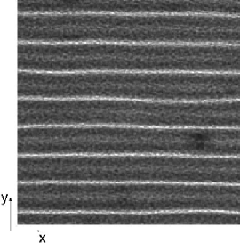
It was found that the threshold voltage for the flexoelectric domains is independent of the polarity of the applied d.c. voltage and on the cell thickness: V. The wavelength of stripe patterns increased linearly with increasing thickness and .
At onset of the flexoelectric stripe patterns no motion of tracers (small particles of m in diameter immersed in NLC) was detected. With increasing d.c. voltage up to V the particles start to move slowly on circular orbits in the plane perpendicular to the domain stripes (Fig.2) signalising the development of hydrodynamic flow in flexoelectric domains.
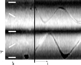

Polarised-optical analysis shows that the director deviates out of the plane of the initial orientation alternatively in the adjacent half-periods of flexoelectric domain. Schematic distribution of the director projection onto the plane ( director) is presented in Fig.2. The dependence of the -component of the tracer velocity on the applied voltage is shown in Fig.3.
When the applied d.c. voltage reaches the value V electroconvection sets in in the form of drifting rolls that break translational invariance in the direction (Fig.4). One observes that inside of the periodic system of narrow channels formed by flexoelectric domains drifting EC rolls develop with some obliqueness with respect to the axis.
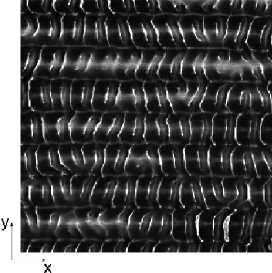
The drift direction is determined by the sign of the director gradient along the normal to the NLC layer in the initial hybrid state. The threshold d.c. voltage, wavelength and oblique angle of EC rolls developing on the background of flexoelectric domains are close to that found in low-frequency a.c. electric field where the first instability is to electroconvection (and the flexoeffect plays a small role) [9, 10]. With further increase of the d.c. voltage the EC mode suppresses the flexoelectric stripe pattern and a dynamic disordered state (DSM) develops. The scenario is reversible.
THEORETICAL ANALYSIS
We consider a nematic layer of thickness with confining plates at . The director is oriented parallel to the axis at and parallel to the axis at . The d.c. voltage applied across the cell is given by and the electric field inside the NLC layer is , where denotes the induced electric potential. The equilibrium director distribution can be found by minimising the total free energy
| (1) |
with the flexoelectric polarization
| (2) |
In the ground state before any instability one has a director distribution that is homogeneous in the plane. All lengths have been measured in units of so that the confining plates are at . We are looking for the stability of this ground state with respect to small director perturbations which are periodic in the direction . Then variation of (S0.Ex1) gives the linearised equations for . The solution of the linear problem was found by expanding in a set of trigonometric functions (Galerkin method, see [10] for detail). The condition for existence of a nontrivial solution gives the neutral curve . The threshold voltage for the flexoelectric instability corresponds to the minimum of with respect to which also defines the critical wavenumber .
Using the one-constant approximation (elastic constants ) one obtains in the limit of small (then one can neglect the induced potential) an approximate analytical expression for the neutral curve
| (3) |
where , and . The threshold voltage and critical wavenumber obtained from (3) are, in the range of validity , close to that found from the numerical solution based on a Galerkin method. Since the coefficients in (3) do not contain the thickness of the NLC layer explicitly, the critical voltage and wavenumber are independent of .
For the material parameters N, corresponding to the average elasticity and dielectric anisotropy of MBBA and choosing C/m (close to that measured recently [11]) one has and (3) gives , that correspond to the critical voltage of flexoelectric stripe patterns V and period in physical units close to that found experimentally.
We have estimated the influence of the velocity perturbations which were neglected in the analysis. The development of out of plane director perturbations leads at first order in to a nonzero charge density . The corresponding bulk force in the Navier-Stokes equation should be balanced by the viscous stresses and therefore drive a velocity . The analysis shows that the corresponding viscous torque acting on the director due to the fluid motion is much smaller than the torques due to elastic, dielectric and flexoelectric contributions. For the experimental value of the angle between the director and the axis, at V slightly above threshold, we obtain for the velocity m/s in physical units (for cell thickness m) which is of the order of that experimentally found, m/s (Fig.3).
CONCLUSION
We have investigated experimentally and theoretically the flexoelectric instability in MBBA with hybrid director configuration. The following sequence of transitions has been found with increasing d.c. voltage: stationary longitudinal flexoelectric domains at onset inside of which some hydrodynamic flow develops above threshold, secondary instability to EC with drifting rolls inside the flexoelectric stripe pattern, and finally suppression of flexoelectric domains and transition to DSM. It was found that the threshold voltage of the flexoelectric domain formation is independent of the thickness of the nematic layer and the spatial period of longitudinal domains increases linearly with increasing thickness which is in good agreement with theoretical predictions. For the first time we have observed the crossover between two spatially periodic instabilities of different nature in a single system: spatially periodic static flexoelectric deformation of the director and drifting EC rolls.
Acknowledgments
We wish to thank W. Pesch for fruitful discussions. Two of us (V.D. and A.K.) wish to acknowledge the hospitality of the University of Bayreuth. Financial support from DFG (Grant 436-RUS-113/220, Graduiertenkolleg “Nichtlineare Spektroskopie und Dynamik” and Grant Kr690/14-1) and INTAS Grant 96-498 is gratefully acknowledged. V.D. is also grateful to the INTAS Grant YSF 99-4036.
References
- [1] L. Kramer and W. Pesch, in Pattern Formation in Liquid Crystals, edited by A. Buka and L. Kramer (Springer-Verlag, New York, 1996), Chap. 6, and references therein.
- [2] R. B. Meyer, Phys. Rev. Lett., 22, 918 (1969).
- [3] Yu. P. Bobylev and S. A. Pikin, Sov. Phys. JETP, 45, 195 (1977).
- [4] M. I. Barnik, L. M. Blinov, A. N. Trufanov and B. A. Umanski, J. Phys. (France), 39, 417 (1978).
- [5] H. P. Hinov and L. K. Vistin, J. Phys. (France), 40, 269 (1979).
- [6] N. V. Madhusudana and V. A. Raghunathan, Liq. Cryst., 5, 1789 (1989).
- [7] W. Thom, W. Zimmermann and L. Kramer, Liq. Cryst., 4, 309 (1989).
- [8] L. Kramer, E. Bodenschatz, W. Pesch, W. Thom and W. Zimmermann, Liq. Cryst., 5, 699 (1989).
- [9] O. G. Akhmetshin, V. A. Delev and O. A. Scaldin, Mol. Cryst. Liq. Cryst., 265, 315 (1995).
- [10] A. Hertrich, A. P. Krekhov and W. Pesch, J. Phys. II (France), 5, 733 (1995).
- [11] T. Takahashi, S. Hashidate, H. Nishijou, M. Usui, M. Kimura and T. Akahane, Jap. J. Appl. Phys. (Pt.1), 37, 1865 (1998).