Rich Variety of Bifurcations and Chaos in a Variant of Murali-Lakshmanan-Chua Circuit
Abstract
A very simple nonlinear parallel nonautonomous LCR circuit with Chua’s diode as its only nonlinear element, exhibiting a rich variety of dynamical features, is proposed as a variant of the simplest nonlinear nonautonomous circuit introduced by Murali, Lakshmanan and Chua(MLC). By constructing a two-parameter phase diagram in the plane, corresponding to the forcing amplitude and frequency , we identify, besides the familiar period-doubling scenario to chaos, intermittent and quasiperiodic routes to chaos as well as period-adding sequences, Farey sequences, and so on. The chaotic dynamics is verified by both experimental as well as computer simulation studies including PSPICE.
I Introduction
Sometime ago, the simplest nonlinear dissipative nonautonomous electronic circuit consisting of a forced series LCR circuit connected parallely to the Chua’s diode, which is a nonlinear resistor, was introduced by Murali, Lakshmanan and Chua [Murali et al., 1994]. The circuit exhibits several interesting dynamical phenomena including period doubling bifurcations, chaos and periodic windows. However, in the paramater regimes investigated, it does not exhibit other important features such as quasiperiodicity, intermittency, period adding sequences, and so on. It will be quite valuable from nonlinear dynamics point of view to construct a simple electronic circuit which exhibits a wide spectrum of dynamical phenomena [Lakshmanan & Murali, 1996]. In this paper, we wish to point out that a rich variety of phenomena can be realized with a simple variant of the above MLC circut, by connecting the Chua’s diode to a forced parallel LCR circuit instead of the forced series LCR circuit. The resultant system exhibits not only the familar period doubling route to chaos and windows but also intermittent and quasiperiodic routes to chaos as well as period adding sequences and Farey sequences, to name a few.
II CIRCUIT REALIZATION OF MLC VARIANT CIRCUIT
The circuit realization of the proposed simple non-autonomous circuit, namely, a variant of the standard MLC circuit, is shown in Fig. 1. It consists of a capacitor(), an inductor(), a

resistor(), an external periodic forcing voltage source and only one nonlinear element(), namley, the Chua’s diode. In the dynamically interesting range, the characteristic of the Chua’s diode is given by the usual three segment piecewise-linear function [Chua et al., 1987; Kennedy, M.P, 1992; Cruz, J.M & Chua, L.O, 1992]. The nonlinear element is added to the familiar forced parallel LCR circuit instead of the series LCR of MLC circuit [Murali et al., 1994]. The resulting circuit can be considered as another important very simple dissipative second order nonautonomous nonlinear circuit and a variant of the MLC circuit. By applying Kirchhoff’s laws to this circuit, the governing equations for the voltage across the capacitor and the current through the inductor are represented by the following set of two first-order non-autonomous diffrential equations:
| (1a) | |||||
| (1b) | |||||
where is a piecewise-linear function defined by Chua et al. and is given by which is the mathematical representaion of the charactierstic curve of Chua’s diode
[Kennedy, M.P, 1992; Cruz, J.M & Chua, L.O, 1992]. The values of the various circuit parameters chosen for our study are as follows: =10.15 nF, =445 mH, =1745 ohms, , , , and .
In equation(1), is the amplitude and is the angular frequency of the externl periodic signal. Rescaling Eq. (1) as , , , , and and then redefining as , the following set of normalized equations are obtained:
| (2a) | |||||
| (2b) | |||||
where , , . Obviously . Here , . Note that the two coupled first order ordinary differential equation given by Eqs. (2) can also be written as a single second order differential equation of the Lienard’s type in the form
| (3) |
We note at this point chaos via torus breakdown generated in a piecewise-linear forced van der Pol equation of the form(3) with asymmetric nonlinearity has been studied by Inaba and Mori [Inaba, & Mori, 1991] sometime ago. However the corresponding circuit uses more nonlinear elements than the present circuit. Now the dynamics of equation or equivalently depends on the parameters , , , and . Then for the above chosen experimental circuit parameter values, we have , , and . We use the amplitude of the external periodic forcing as the control parameter and carry out a numerical simulation of Eqs. (2) either by integrating Eqs. (2) or by solving Eq. (3) analytically and numerically, for increasing values of . For the above choice of parameters the numerical simulation of Eqs. (2) exhibits novel dynamical phenomena.
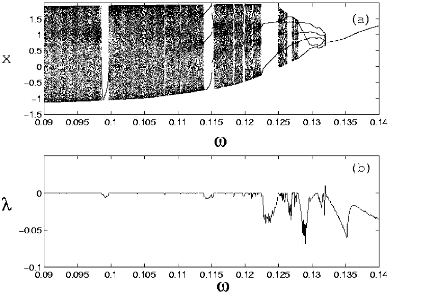
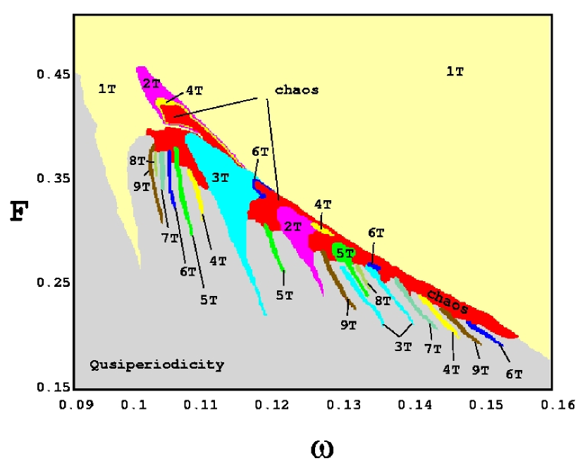
To begin with we have carried out an experimental study of the dynamics of the circuit given by Fig. 1. The driving amplitude() is slowly increased from 0V and the response of the system is observed to progress through a series of transition from periodic motion to aperiodic motion. When the driving amplitude (corresponding to the autonomous case), a period-1 limit cycle is observed. By increasing the amplitude from zero upwards, the circuit of Fig. 1 is found to exhibit a quasiperiodic(torus) attractor which then transits to chaos via torus breakdown, followed by periodic windows, period-adding sequences etc. We have confirmed these results also by using the standard 4th-order Rugne-Kutta integration routine and carrying out a numerical analysis of Eqs. (2) or equivalently Eq. (3) with the rescaled circuit parameters of Fig. 1 as given above. We have observed a series of appearence and disappearence of the quasiperiodic (torus) and phase locking(periodic) attractors, and period-adding sequences alternatively by varying the amplitude of the external source at fixed frequency. Illustrated in Fig. 2 is the two paramater phase diagram which is plotted in the () plane. In particular, quasiperiodic motions and period-adding sequences besides the standard bifurcation sequences have been observed in regions of the lower drive amplitude () and frequency () values. For example, typical quasiperiodic attractors exist in the range , and =. Similarly, a period adding sequence exists for and , a period-doubling bifurcation sequence for , and , and also type I intermittency has been identified for and . In addition for and , as well as for , and for , , Farey sequences [Kaneko, 1986] exist. The regions of chaos are also indicated in Fig. 2. Finally Fig. 3(a). represents the one-parameter bifurcation in the plane, for which consists of quasiperiodicity, chaos, windows, period adding sequences and the familiar period doubling bifurcation sequence, intermittency and so on. In fig. 3(b) its corresponding maximal Lyaponov spectrum in is plotted. Also
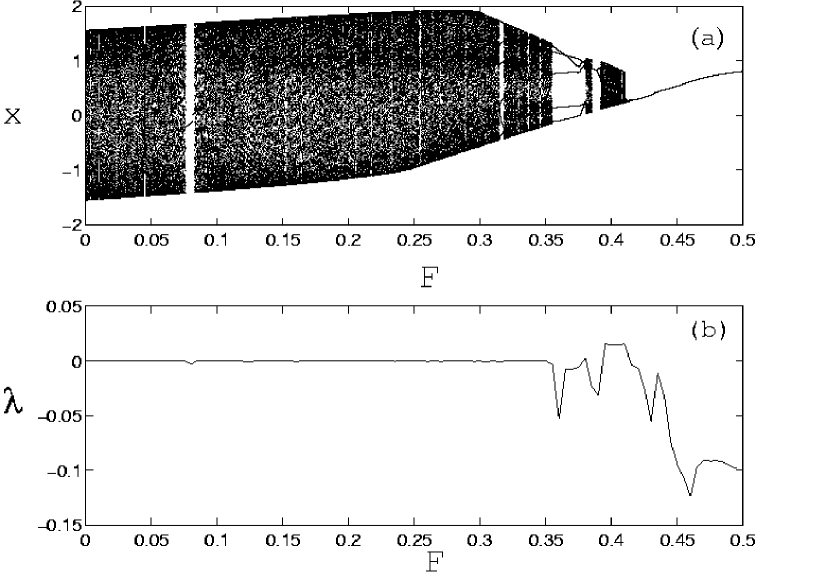
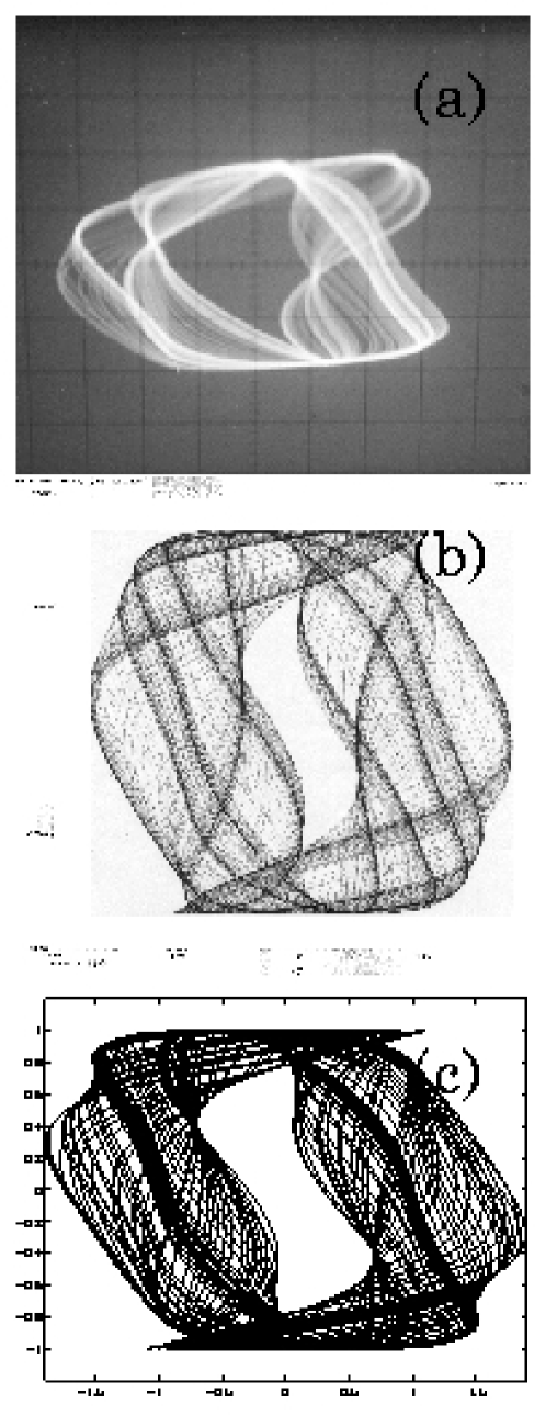
fig. 4(a) represents the one-parameter bifurcation in the plane, for , fig. 4(b) depicts the corresponding maximal Lyaponov spectrum . Further, the experimental results obtained for a choice of circuit parameters were also confirmed by using the PSPICE [Roberts, 1997] deck available to simulate the behavior of the circuit in Fig. 1. In Fig. 5, we have included for comparison the chaotic attractor corresponding to in Eq. (1) for experimental and SPICE analysis and corresponding numerical simulation for amplitude in Eq. (2).
.
III CONCLUSION
In this letter, we have presented a very simple second order dissipative nonlinear nonautonomous circuit which is a variant of the MLC circuit and carried out. It is shown to possess a very rich variety of dynamical phenomena. In view of the appearance of several ubiquitous routes to chaos such as quasiperiodicity, intermittency, period doubling, period-adding and Farey sequence in such a single but simple circuit, one can make use of the circuit in varied investigations on chaotic dynamics and applications, including spatio-temporal studies. A more detailed analysis of these aspects will be published elsewhere.
Acknowledgements.
The work of M.Lakshmanan forms part of a Department of Science and Technology, Government of India research project. We are thankful to Mr. A. Venkatesan for his assistance for numerical analysis.REFERENCES
-
Chua, L. O., Desoer, C.A. & Kuh,E. S. Linear and Nonlinear Circuits (McGraw-hill, New York).
-
Cruz, J. M, & Chua, L. O. “A CMOS IC nonlinear reisitor for Chua’s circuit,” IEEE Trans. Circuits Syst-I., vol.39, pp.985-995.
-
Inaba, N. & Mori, S. “Chaos via torus break down in a piecwise-linear forced van der Pol oscillator with a diode,” IEEE Trans. Circuits and Syst-I., vol.38, pp.398-409.
-
Kaneko, K. Collapse of Tori and Genesis of Chaos in Dissipative Systems (World Scientific, Singapore).
-
Kennedy, M. P. “Robust op amp realization of Chua’s circuit,” Frequanz, vol.46, pp.66-80.
-
Lakshmanan, M. & Murali K. Chaos in Nonlinear Oscillators: Controlling and Synchronization (World Scientific, Singapore) .
-
Murali, K., Lakshmanan, M. & Chua, L. O. “The simplest dissipative nonautonomous chaotic circuit,” IEEE Trans. Circuits Syst-I., vol.41, pp.462-463.
-
Murali, K., Lakshmanan, M. & Chua,L. O. “Bifurcation and chaos in the simplest dissipative nonautonomous circuit,” Int.J.Bifurcation and Chaos, vol.4, pp.1511-1524.
-
Roberts, W. SPICE (Oxford University Press, New York).