Spatiotemporal Communication with Synchronized Optical Chaos
Abstract
We propose a model system that allows communication of spatiotemporal information using an optical chaotic carrier waveform. The system is based on broad-area nonlinear optical ring cavities, which exhibit spatiotemporal chaos in a wide parameter range. Message recovery is possible through chaotic synchronization between transmitter and receiver. Numerical simulations demonstrate the feasibility of the proposed scheme, and the benefit of the parallelism of information transfer with optical wavefronts.
PACS numbers: 05.45.Vx, 42.65.Sf, 05.45.Xt
One of the most appealing applications of chaos is the possibility of using chaotic signals as broad-band carriers of information, which could lead to a simple implementation of spread-spectrum communication systems. Many of the schemes devised so far to that end are based on the occurrence of synchronization between two chaotic systems [1]. Following the original implementation of this approach in electronic circuits [2, 3], special attention has been paid to using optical systems [4], which offer the possibility of high-speed data transfer in all-optical communication systems [5]. Optical chaotic communication was recently demonstrated in fiber lasers [6], diode lasers with external nonlinearity [7], and diode lasers with optical feedback [8].
In most optical realizations of communications with chaos, the message to be encoded drives the nonlinear transmitter, so that the message and carrier become mixed in a nontrivial way. The resulting output is injected into a receiver, which, upon synchronization to the transmitter, allows for recovery of the original signal. The optical schemes developed so far have used purely temporal chaotic signals as information carriers. The present Letter proposes a nonlinear optical device exhibiting spatiotemporal chaos as the basis of a communication system capable of transmitting information in space and time. Chaotic behavior in spatial degrees of freedom has recently been used for multichannel communication with multimode semiconductor lasers [9]. In that case, however, only variations of the electric field along its propagation direction were considered. Information was encoded in the different longitudinal cavity modes, demonstrating a technique for multiplexing. Spatiotemporal communication, on the other hand, utilizes the inherent large scale parallelism of information transfer that is possible with broad-area optical wavefronts. As in the previous cases [10], our scheme requires the existence of synchronization between transmitter and receiver. Synchronization of spatiotemporal chaos has been investigated extensively in previous years, but most studies have been restricted to nonlinear oscillator arrays [11], coupled map lattices [12] and model partial differential equations [13, 14, 15]. Our system, on the other hand, is represented by an infinite-dimensional map spatially coupled in a continuous way by light diffraction.
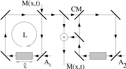
The experimental setup is shown schematically in Fig. 1. Two optical ring cavities are unidirectionally coupled by a light beam extracted from the left ring (the transmitter) and partially injected into the right one (the receiver). Each cavity contains a broad-area nonlinear absorbing medium, and is subject to a continuously injected plane wave . Light diffraction will be taken into account during propagation through the medium, in such a way that a nonuniform distribution of light in the plane transverse to the propagation direction may appear. In fact, an infinite number of transverse modes will in principle be allowed to oscillate within the cavity. A spatiotemporal message can be introduced into the transmitter’s cavity, and recovered as in the receiver as explained below.
When no message is introduced and the receiver is absent, the transmitter is a standard nonlinear ring cavity, well known to exhibit temporal optical chaos [16]. When transverse effects due to light diffraction are taken into account, a rich variety of spatiotemporal instabilities appear [17], giving rise to solitary waves [18], period-doubling bifurcations [19], spatial patterns [20], and spatiotemporal chaos [21, 22]. This latter behavior is the one in which we are interested, since such chaotic waveforms will be used as information carriers in our setup.
The propagation of light through the nonlinear medium can be described by the following equation for the slowly-varying complex envelope of the electric field (assumed to be linearly polarized) in the n-th passage through the resonator [21]:
| (1) |
The first term on the right-hand side of (1) describes diffraction, and the second saturable absorption. The propagation direction is denoted by , whereas is a vector in the plane orthogonal to the propagation direction. Equation (1) obeys the boundary condition
| (2) |
which corresponds to the infinite-dimensional map that is the object of our analysis. in (2) denotes the input of the nonlinear medium, which has length . The total length of the cavity is . Other parameters of the model are the absorption coefficient of the medium, the detuning between the atomic transition and cavity resonance frequencies, the transmittivity of the input mirror, and the total return coefficient of the cavity (fraction of light intensity remaining in the cavity after one round trip). The injected signal, with amplitude and wavenumber , is taken to be in resonance with a longitudinal cavity mode.
Previous studies have shown that for , model (1)-(2) exhibits irregular dynamics in both space and time for large enough [21]. This spatiotemporally chaotic behavior can become synchronized to that of a second cavity, also operating in a chaotic regime, coupled to the first one as shown in Fig. 1. The coupling mechanism can be modeled in the following form [10]:
| (3) | |||
| (4) |
where the application represents the action of the map (2) in every round trip. The coupling coefficient is given by the transmittivity of the coupling mirror CM (Fig. 1). The superindices 1 and 2 represent the transmitter and receiver, respectively. Earlier studies have shown that local sensor coupling is enough to achieve synchronization of spatiotemporal chaos in model continuous equations [23]. In our optical model, however, the whole spatial domain can be coupled to the receiver in a natural way.
To estimate the synchronization efficiency of scheme (4), we have evaluated the synchronization error [14] , where is the size of the system. This quantity has been computed for increasing values of the coupling coefficient , by numerically integrating model (1)-(2) for both transmitter and receiver operating in a regime of spatiotemporal chaos, and using the coupling scheme (4). Simulations have been performed in a 1-d lattice of 1000 cells of size spatial units, using a pseudospectral code for the propagation equation (1). Similar parameter values to those of Ref. [21] are used here. The initially uncoupled systems evolve in time starting from arbitrary initial conditions, and after 100 round trips, when their unsynchronized chaotic dynamics is fully developed, coupling is switched on. The synchronization error is measured 100 round trips later. The results are shown in Fig. 2(a), which plots the value of for increasing coupling strengths. According to these results, a high degree of synchronization can be obtained for couplings as low as 40%.


Another important issue to address at this point is how sensitive synchronization is to differences between the two cavities. We have extensively analyzed the effect of different parameter mismatches on the synchronization error . Our results indicate that parameters such as the absorption coefficient , the detuning and the nonlinear medium length can be varied as much as 50% and still keep below . More sensitive parameters are the total length of the cavity [due to its appearance in the phase-change term of (2)] and the amplitude of the injected signal. Since the two cavity lengths can be matched experimentally, we now examine in detail the effect of a mismatch in . This parameter could be controlled in real time if necessary, and hence act as a control parameter for synchronization. The variation of versus relative mismatch of is shown in Fig. 2(b). It can be seen that synchronization is quickly degraded as the two injected amplitudes differ, with increasing well above for mismatches of the order of 1%. Therefore, the value of is critical for obtaining synchronization in the system.
We now use the synchronizing system described above to encode and decode information in space and time using the spatiotemporal chaotic carrier. We modify the scheme of Eqs. (4) according to Fig. 1, which leads to:
| (5) | |||
| (6) | |||
| (7) |
If synchronization between transmitter and receiver is achieved, it will be possible to decode the signal by simply subtracting the transmitted signal and the one in the receiver: . In the case of no mismatch, it can be seen analytically in a straightforward way that, as the coupling coefficient tends to 1, the difference , which corresponds to perfect synchronization, and hence to perfect message recovery. It should be noted that the message is not merely added to the chaotic carrier, but rather the former is driving the nonlinear transmitter itself. Therefore, as we will see in what follows, the amplitude of the message need not be much smaller than that of the chaotic signal to provide good masking of the information.
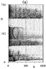
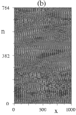
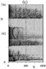
The scheme described above has been tested by encoding an analog 1-d signal with complex evolution in space and time. The sample signal chosen is the spectrogram of a sample of speech. Chaotic systems have been used in the past to encode speech waveforms [3, 10], but the information that such signals provide is insufficient for voice-recognition purposes. Spectrograms, on the other hand, contain information on a broad range of frequencies as time evolves. Figure 3(a) shows a grayscale spectrogram of the word “compute”, with frequency components in the horizontal axis and time evolving from bottom to top. We will encode the frequency information in the 1-d transverse direction of our setup. The real part of the transmitted signal is shown in Fig. 3(b) for a message amplitude maximum of 0.5. This value should be compared to the maximum intensity of the chaotic carrier, which oscillates between 1 and 10, approximately, for the parameters chosen. The spatiotemporal chaotic state of the signal can be clearly observed. Finally, Fig. 3(c) shows the detected message, for a 90% coupling between transmitter and receiver.
Figure 3 qualitatively shows that, even though coupling between transmitter and receiver is not complete, information varying in time and space can be successfully transmitted and recovered with the setup described in Fig. 1. In order to have a quantitative measure of this effect, we have estimated the mutual information between input and output message signals, and its dependence on several system parameters. To that end, we discretize the values of and in space-time points, and compute the probability distributions , , and the joint probability , where and are the different values that and may take, respectively. A measure of the mutual information between the two sets of data is given by , where the sums run over all possible values of and . This mutual information function is 0 for completely independent data sets, and equal to the entropy of the common signal, , when the two messages are identical. Figure 4(a) shows the value of the mutual information , for the message encoding proposed in Fig. 3, versus the coupling coefficient . It can be seen that, as increases, grows from 0 to perfect recovery, corresponding to the entropy of the input image, given by the horizontal dashed line in the figure. This result shows that, even though good synchronization appears for , satisfactory message recovery requires coupling coefficients closer to unity. This can also be seen by examining the behavior of the entropy of the recovered image, plotted as empty squares in Fig. 4(a): for values of substantially smaller than 1, the entropy of the recovered data is appreciably larger than that of the input message, indicating a higher degree of randomness in the former. Finally, the behavior of the mutual information in the presence of noise is shown as empty diamonds in Fig. 4(a). Uncorrelated, uniformly distributed noise is added continuously to the communication channel, with an amplitude 1% that of the message. The results show that the scheme is reasonably robust, in agreement with previous studies [9]. A more systematic analysis of this issue is in progress.
We have also examined the effect of parameter mismatch on the efficiency of message recovery. As in the synchronization characterization, we have concentrated on the influence of the most sensitive parameter, namely the amplitude of the injected signal. The data plotted in Fig. 4(b) show that a slight mismatch in the value of will degrade recovery, by leading to values of much smaller that the entropy of the input message, and to a recovered message with substantially larger entropy than the original.


Finally, we should note that our setup is also suitable for the transmission of two-dimensional information. To illustrate this, we have chosen to encode a static 2-d image with the same mechanism discussed above. Figure 5 shows the results obtained in this case. As in Fig. 3, the left plot depicts the input message, the middle plot the real part of the transmitted signal (a snapshot of it, in this case), and the right plot the recovered data. The message amplitude maximum is now 0.01. Simulations are now performed on a square array with 256256 pixels of width . The image is clearly recognizable even though the coupling coefficient is now as low as 0.7.

In conclusion, we have proposed a nonlinear optical model system that allows encoding and decoding information in space and time by means of spatiotemporal chaos synchronization. Synchronization occurs for a wide range of coupling values and system parameters. Spatiotemporal information can be successfully recovered for large enough coupling between transmitter and receiver, and for small enough parameter mismatches. The proposed setup could be experimentally implemented upon identification of a suitable broad-area nonlinear medium.
Financial support from NATO (project CRG.971571) and Office of Naval Research is acknowledged. J.G.O. also acknowledges support from DGES-Spain (projects PB96-0241 and PB98-0935). Spectrogram provided by the Center for Spoken Language Understanding, Oregon Graduate Institute of Science and Technology. Two-dimensional image provided by A+ Free Clip Art.
REFERENCES
- [1] L.M. Pecora and T.L. Carroll, Phys. Rev. Lett. 64, 821 (1990).
- [2] L. Kocarev, K.S. Halle, K. Eckert, L.O. Chua, and U. Parlitz, Int. J. Bif. Chaos 2, 709 (1992).
- [3] K.M. Cuomo and A.V. Oppenheim, Phys. Rev. Lett. 71, 65 (1003).
- [4] P. Colet and R. Roy, Opt. Lett. 19, 2056 (1994).
- [5] C.R. Mirasso, P. Colet, and P. García-Fernández, IEEE Phot. Technol. Lett. 8, 299 (1996).
- [6] G.D. VanWiggeren and R. Roy, Science 279, 1198 (1998); ibid. Phys. Rev. Lett. 81, 3547 (1998).
- [7] J.P. Goedgebuer, L. Larger, and H. Porte, Phys. Rev. Lett. 80, 2249 (1998); Y. Liu and P. Davis, Opt. Lett. 25, 475 (2000).
- [8] S. Sivaprakasam and K.A. Shore, Opt. Lett. 24, 1200 (1999); I. Fischer, Y. Liu, and P. Davis, Phys. Rev. A 62, 011801(R) (2000).
- [9] J.K. White and J.V. Moloney, Phys. Rev. A 59, 2422 (1999).
- [10] H.D.I. Abarbanel and M.B. Kennel, Phys. Rev. Lett. 80, 3153 (1998).
- [11] L. Kocarev and U. Parlitz, Phys. Rev. Lett. 77, 2206 (1996).
- [12] J.H. Xiao, G. Hu, and Z. Qu, Phys. Rev. Lett. 77, 4162 (1996); Y. Jiang and P. Parmananda, Phys. Rev. E 57, 4135 (1998).
- [13] A. Amengual, E. Hernández-García, R. Montagne, and M. San Miguel, Phys. Rev. Lett. 78, 4379 (1997).
- [14] L. Kocarev, Z. Tasev, and U. Parlitz, Phys. Rev. Lett. 79, 51 (1997).
- [15] S. Boccaletti, J. Bragard, and F.T. Arecchi, Phys. Rev. E 59, 6574 (1999).
- [16] K. Ikeda, Opt. Commun. 30, 257 (1979); K. Ikeda, H. Daido, and O. Akimoto, Phys. Rev. Lett. 45, 709 (1980).
- [17] D.W. McLaughlin, J.V. Moloney, and A.C. Newell, Phys. Rev. Lett. 54, 681 (1985).
- [18] D.W. McLaughlin, J.V. Moloney, and A.C. Newell, Phys. Rev. Lett. 51, 75 (1983); J.V. Moloney, Phys. Rev. A 33, 4061 (1986).
- [19] M. Haeltermann, Opt. Commun. 100, 389 (1993).
- [20] M. Le Berre, A.S. Patrascu, E. Ressayre, and A. Tallet, Opt. Commun. 123, 810 (1996).
- [21] M. Sauer and F. Kaiser, Int. J. Bif. Chaos 6, 1481 (1996); ibid. Phys. Rev. E 54, 2468 (1996).
- [22] M. Le Berre, A.S. Patrascu, E. Ressayre, and A. Tallet, Phys. Rev. A 56, 3150 (1997).
- [23] L. Junge and U. Parlitz, Phys. Rev. E 61, 3736 (2000).