Secure Digital Signal Transmission by Multistep Parameter Modulation and Alternative Driving of Transmitter Variables
Abstract
The idea of secure communication of digital signals via chaos synchronization has been plagued by the possibility of attractor reconstruction by eavesdroppers as pointed out by Pérez and Cerdeira. In this Letter, we wish to present a very simple mechanism by which this problem can be overcome, wherein the signal is transmitted via a multistep parameter modulation combined with alternative driving of different transmitter variables, which makes the attractor reconstruction impossible. The method is illustrated by means of the Lorenz system and Chua’s circuit as examples.
pacs:
PACS Number(s): 05.45.X, 05.45.VThe work of Pecora and Carroll [1990,1991] on synchronization of chaotic signals has suggested the possibility of secure communication using chaos synchronization. They have shown that two chaotic systems can be synchronized when they are linked by a common signal (driving signal) provided the Lyapunov exponents of the subsystem are all negative. Following this suggestion a number of methods have been proposed for secure communication [Lakshmanan & Murali, 1996; Hayes et al., 1993; Cuomo & Oppenheim, 1993; Murali & Lakshmanan, 1993a,1993b; Kocarev & Parlitz, 1995; Zhang et al., 1998] with the help of chaotic signals. Cuomo and Oppenheim [1993] have shown that a small difference between the corresponding parameters in the drive and response systems will cause synchronization frustration between the transmitter and receiver variables. Using this property, they have suggested a very simple method for digital signal transmission and illustrated it with the Lorenz system. However, Pérez and Cerdeira [1995] have pointed out that it is possible to reconstruct the message by an eavesdropper from a simple return map formed by the extrema of the modulated driving signal (Here, the driving signal is used as a carrier signal in the digital signal transmission. In our method the digital message is imposed on this carrier signal through parameter variation. So, we call the driving signal bearing the digital message as modulated driving signal and the modulation as parameter modulation.), even without synchronization with the receiver system. To overcome the above problem several methods have been suggested by many authors recently [Murali & Lakshmanan, 1998; Mensour & Longtin, 1998; Minai & Pandian, 1998]: Private communication using compound chaotic signal technique, using delay-differential equations technique, communication through noise and so on. However, most of the above methods are very complicated and are often difficult to implement. In this Letter, we describe a simple method by which the digital signal can be highly masked with the chaotic signal by using a multistep parameter modulation and show how it can be further complicated by introducing two different drive signals alternatively instead of a single drive signal. As a result, reconstruction of the message becomes virtually impossible and this provides further development in the technique of secure communication using chaotic signals.
In order to present our method, we make use of the dynamical system used by Cuomo and Oppenheim [1993] namely the Lorenz system. The associated evolution equations at the transmitter end are
| (1) | |||||
| (2) | |||||
| (3) |
while at the receiver end, corresponding to an -drive, they read as
| (4) | |||||
| (5) | |||||
| (6) |
where and the parameter chosen for the purpose of modulation can have either the value or . The numerical value of the parameter at the receiver end is kept at a constant value 4.0, while in the transmitter circuit it is changed between two values, namely 4.0 and 4.4, when the digital signal is zero and one, respectively. The transmitted digital message is reconstructed by using the synchronization error power . It is negligible when the transmitter and the receiver systems are synchronized, while it has some finite value when they are not synchronized. Thus the receiver will synchronize with the transmitter when the parameter in the latter takes a value , while asynchronization takes place when at the transmitter. It may be noted that instead of the -drive at the receiver end one can as well use the -drive in which case the eq.(2) will be modified as
| (7) | |||||
| (8) | |||||
| (9) |
In the work of Pérez and Cerdeira [1995], it has been shown that even without any receiver circuit, one can unmask the message from the modulated drive signal. In this reference, the maxima and minima are collected from the modulated driving signal and the new varibles and are defined. The plot of the return map for Vs is shown in fig. 1. Note that there are 3 segments in the attractor each one of which is further split into two strips (one corresponding to the high state and the other corresponding to low state of the digital message). It is obvious that the split in the attractor is due to the change of the parameter at the sender end between the values and . From the return map one can easily unmask the message by finding the strip on which the point falls in each segment of the attractor. We can call the above procedure as a single-step parameter modulation, since can have only one value for one state of the message (that is, can take only a single value for any high state in the digital message and only for the low state digital signal at the transmitter). The crux of the problem is then that from the nature of the chaotic attractor and the return map of the Lorenz system, one can have only eight possibilities of message reconstruction from which one can easily discover the actual message. Then, one possible way to overcome such a reconstruction is to increase the number of possible ways by which message can be reconstructed to an unmanageable level and thereby eliminating the possibility of identifying the correct message.
In our work, we have effected two changes in the mode of transmission of the digital message by the parameter modulation in order to complicate the attractor in the return map. Firstly, in the sender part, instead of using a single-step parameter modulation, we use a multi-step parameter modulation, where for one state of the digital message (either or ), the parameter in the sender equation is assigned to have any one of the ’’ preassigned values ( and sufficiently large), while at the receiver part we use receiver subsystems with different parameters. We call the number as the step of the modulation. Secondly, we will use both and signals to drive the receiver subsystems alternatively during the transmission as indicated in eqs.(2) and (3).
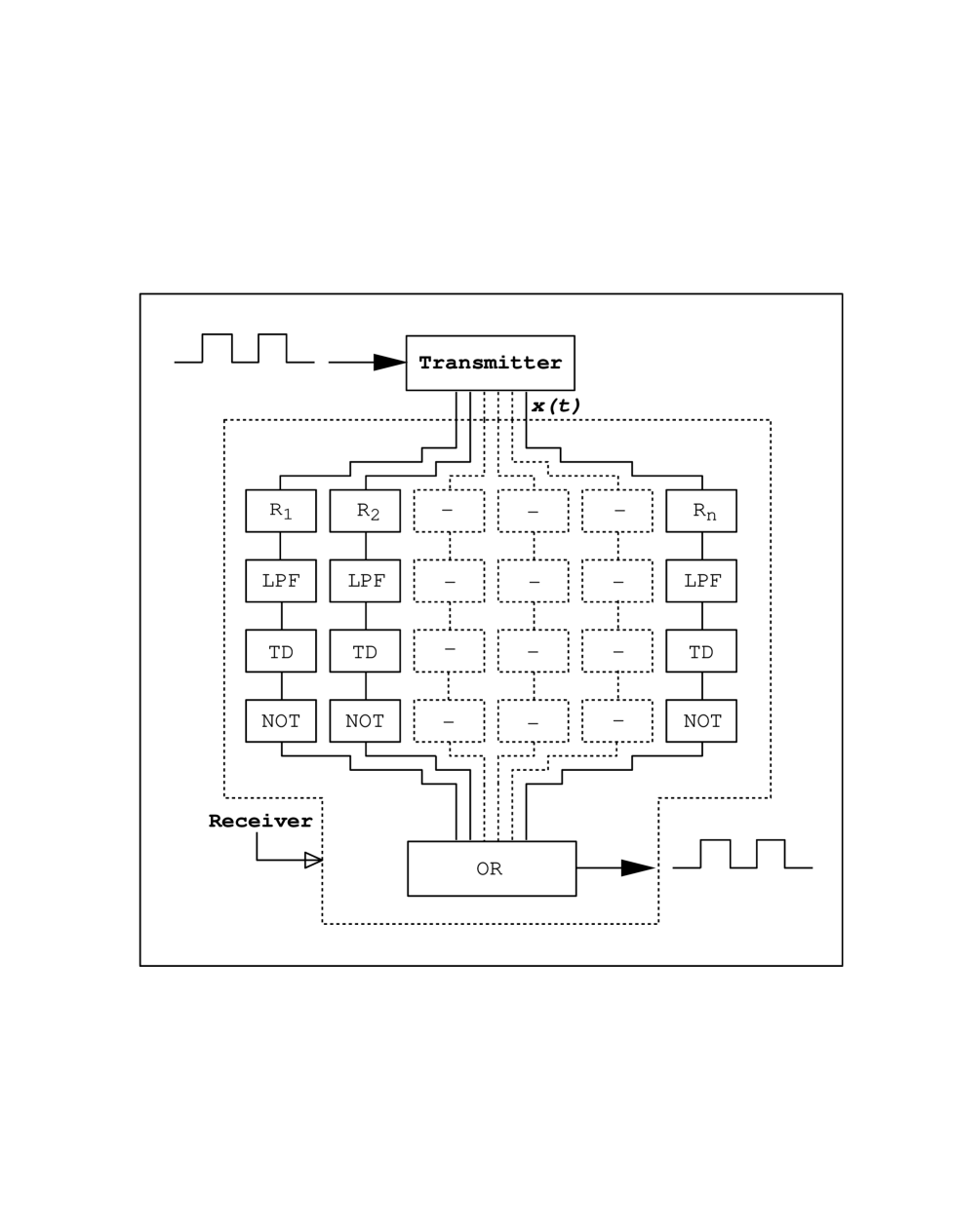
The block diagram of the transmitter and the receiver with modulation step is shown in fig. 2, where R1,R2,…Rn are the subsystems of the receiver. Each one of the s is assigned a specific value among the chosen parameter values which are used to impose the high state of the digital message on the driving signal. The synchronization error power at the output of each subsystem is fed into low pass filters(LPFs) separately. Then the filtered signal is converted into a digital signal at threshold detectors(TD)[Cuomo & Oppenheim, 1993], which is then passed through NOT gates in order to invert and to confirm with the original assignment of high and low states of the digital signal. An OR gate at the receiver combines all the outputs from the NOT gates. Thus, when the digital message imposed on the driving signal is ’’, any one of the subsystems at the receiver will synchronize and the output at the OR gate will be ’’. None of the subsystems will synchronize, if the modulated digital message is zero, and hence ’’ will be the output of the OR gate.
We illustrate our method in the case of the Lorenz system with the same parameters used by Pérez and Cerdeira [1995] and with the modulation step as small as . The Lorenz system (1) is known to exibit chaotic behavior when the parameter takes any value between and . One can assign a specific value to within this range for the purpose of modulation. We select the region for the illustration of our method. As an example, the parameter in the transmitting system is allowed to take any one of the five values for high state of the digital signal, while it can have any one the values for the low state. In the receiver part, we use 5 subsystems with the modulation parameter fixed at respectively.
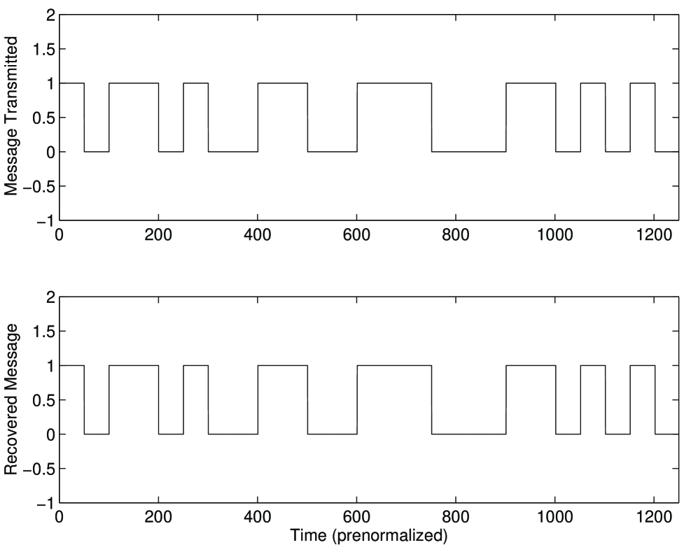
The method works as follows. Suppose we have a high state in the digital message, to start with. Then, the receiver is driven by the modulated driving signal with modulation parameter . For the next high state in the message the modulation is done with = and this process continues upto the value . Then the value of is reset to . This procedure is also applicable to the low state of the message but with the modulation parameter() taking the values in that order. In the receiver part, all the subsystems are driven by the modulated driving signal. However, the subsystems and will synchronize only for the values of modulation parameter at the transmitter, respectively. When the synchronization is achieved in a subsystem, the error power will be below the threshold level and so the message obtained from TD will be at the low state. It is inverted to the high state using the NOT gate. But a low state is attained by the digital message at the NOT gate, if the subsystem is not synchronized. Thus a high state message is obtained as an output at the OR gate if any one of the subsystems is synchronized and a low state digital message is recovered when asynchronization takes place at all the subsystems. A test digital message transmitted and recovered by this scheme by numerical simulation is shown in fig. 3.
Actually the above possibility is only a test case and has been discussed for illustrative purpose. One can modulate in a random way also (that is, at the transmitter circuit, can be assigned any one of the chosen values in a random manner) rather than in a predetermined way. The method presented here is applicable equally well to such possibilities also.
The return map constructed using the modulated driving signal is shown in fig. 4. Here we have 10 strips in each segment. This corresponds to strips, where is the step of the parameter modulation. Because of the complicated nature of the return map it is very difficult to find the strip on which the point falls in each segment of the attractor and so it is difficult to unmask the message from the return map. Even if one can identify the location of the points in the strip, still one has a serious difficulty in assigning ’0’ and ’1’ to the strips since there are chances to make a mistake, for a successful reconstruction of the message. For , there are 7 chances [Pére & Cerdeira, 1995] of making a mistake during the unmasking of the message from the modulated driving signal and for , this chances increases to a high value of 1,067,462,647 (of the order of ). So it is almost impossible to unmask the message masked by our scheme, even at as low value as .
We can complicate the attractor in the return map further by the second method. In the Lorenz system, synchronization [Pecora & Carroll, 1991] is possible by both driving and driving, since the conditional Lyapunov exponents are all negative in both the cases. We use this property in the second method. Here the principle of transmitting and receiving the message is the same as described above, but instead of using a single driving signal , we now use both and as the driving signals alternatively. For the odd digital bits, we drive the receiver by modulated whereas the even digital bits are transmitted using modulated as the driving signal. The block diagram of the transmitting and receiving systems with modulation step is shown in fig. 5. Here we use subsystems in the receiver, subsystems for each value of modulation parameter (which are used for the transmission of high state of the digital message), one with modulated driving and the other with modulated driving. The recovered message is similar to the one obtained in our previous method. The return map constructed from the modulated drive signals (modulated x(t) and modulated y(t)) for the modulation step =5 is shown in fig. 6. From the return map, it is impossible to unmask the message since the attractor of the drive signal is merged with the attractor of the driving signal.
We have also applied our scheme to the simplest autonomous Chua circuit generator of the chaotic signal [Madan, 1993; Chua et al., 1992]. We have used the unnormalized circuit equations
| (10) | |||||
| (11) | |||||
| (12) |
where during our verification with as the modulation parameter. The other parameters value used are , and . The Chua circuit can also be synchronized either with the driving signal or with and so we can again use them as alternative drive variables. One can assign any value to the parameter between to , except in some small regions where periodic windows occur. Here the largest Lyapunov exponent calculated has positive values and hence the circuit exibits chaotic behaviour. We find from our numerical studies that it is even more difficult to extract message in this case with multiparameter modulation compared to the Lorenz system, due to the nature of the chaotic attractor.
Thus, in this Letter, we have described two simple and straightforward methods to complicate the attractor in the return map of the modulated driving signal: One with multi-step parameter modulation by using a number of values to the modulation parameter and the other by using alternative and driving combined with multistep parameter modulation. We have illustrated them with the Lorenz system and Chua’s circuit as examples. We conclude that it is almost impossible to reconstruct the digital message transmitted in our scheme by the use of the return map formed by the modulated driving signal.
Acknowledgements.
This work has been supported by the National Board of Higher Mathematics, Department of Atomic Energy, Government of India and the Department of Science and Technology, Government of India through the research projects. The authors thank Dr. K. Murali for many valuable suggestions.REFERENCES
-
Chua, L.O., Kocarev, Lj., Eckert, K. & Itoh, M. [1992] “ Experimental chaos synchronization in Chua’s circuit” Int. J. Bifurcation and Chaos 2 705-708.
-
Cuomo, K.M. & Oppenheim, A. V. [1993] “Circuit implementation of synchronized chaos with application to communication” Phys. Rev. Lett. 71 65-68.
-
Hayes, S., Grebogi, C. & Ott, E. [1993] “Communicating with chaos” Phys. Rev. Lett. 70, 3031-3035.
-
Kocarev, L. & Parlitz, U. [1995] “General approach for chaotic synchronization with applications to communication” Phys. Rev. Lett. 74 5028-5031.
-
Lakshmanan, M. & Murali, K. [1996] Chaos in Nonlinear Oscillators: Controlling and Synchronization (World Scientific, Singapore).
-
Madan, R. N., [1993] Chua’s circuit: A Paradigm for Chaos (World Scientific, Singapore).
-
Mensour, B. & Longtin, A. [1998] “Synchronization of delay-differential equations with application to private communication” Phys. Lett. A244, 59-70.
-
Minai, A. A. & Pandian, T. D. [1998] “Communicating with noise: How chaos and noise combine to generate secure encryption keys” Chaos 8 621-628.
-
Murali, K. & Lakshmanan, M. [1993] “Transmission of signals by synchronization in a chaotic van der pol-duffing oscillator” Phys. Rev. E48, R1624-1626
-
Murali, K. & Lakshmanan, M. [1993] “Synchroning chaos in driven chua’s circuit” Int. J. Bifurcations Chaos 3, 1057-1066.
-
Murali, K. & Lakshmanan, M. [1998] “Secure communication using a compound signal from generalized synchronizable chaotic systems” Phys. Lett. A241, 303-310.
-
Pecora, L. M. & Carroll, T. L. “Synchronization in chaotic systems” Phys. Rev. Lett. 64, 821-823 (1990);
-
Pecora, L. M. & Carroll, T. L. “Driving systems with chaotic signals” Phys. Rev. A44, 2374-2383.
-
Pérez, G. & Cerdeira, H.A. [1995] “Extracting messages masked by chaos” Phys. Rev. Lett. 74, 1970-1973.
-
Zhang, Y., Dai, M., Hua, Y., Ni, W, & Du, G. [1998] “Digital communication by active-passive-decomposition synchronization in hyperchaotic systems” Phys. Rev. E58 3022-3027.