Directional coupling of optical signals by odd dark beams with mixed phase dislocations
Abstract
Numerical simulations on the evolution of step-screw and edge-screw optical phase dislocations in bulk saturable self-defocusing nonlinear media are presented, with emphasis on their ability to induce steering waveguides for signal beams (pulses). Two schemes for directional coupling of such signals, both ensuring reasonable coupling-to-cross-talk efficiency ratio, are investigated. The parameters useful for performance optimization of the couplers are discussed.
pacs:
PACS numbers: 42.65.Tg, 42.65.KyI Introduction
Dark spatial solitons (DSSs) formed in bulk self-defocusing Kerr-type nonlinear media (NLM) are able to guide co-propagating probe beams/pulses [1, 2, 3]. The physical mechanism underlying is the intensity-dependent refractive-index change in a plane perpendicular to the propagation direction. Weak signal beams passing along these optically induced gradient waveguides [4] are subject to effective induced-phase modulation and are trapped. In photorefractive NLM [5] the situation is even more spectacular [6]. Because of the wavelength-dependent material response, dark spatial solitons generated at low powers but at a photosensitive wavelength are able to guide and steer much more powerful ‘signal’ beams at non-photosensitive wavelengths. This is confirmed for photovoltaic [7], biased [8] and quasi-steady-state [9] photorefractive solitons and seems to hold also for incoherent dark solitons [10].
Bright signal beams/pulses can be deflected by both electronically [11] and optically induced prisms [12]. When they are guided by DSSs, the same can be done by manipulating the transverse dynamics of the dark beams. The transverse velocity of an optical vortex soliton (OVS) has a radial and an angular component arising from the transverse phase and intensity gradients, respectively [13, 14]. Two practical ways to control the vortex rotation have their origin in the Guoy phase shift on both sides of the background beam waist [14, 15] and in the interaction of ordered structures of OVSs [16] controlled by the topological charges. OVS steering is demonstrated by superposition of a weak incoherent background field [17]. Operation of planar Y-junction splitters for signal beams is demonstrated in both Kerr-type [18] and photorefractive NLM [19] with pairs of grey DSSs born from even initial conditions. The possibility to branch a single input probe beam into ordered structures of sub-beams by quasi-two-dimensional DSSs is demonstrated numerically in Ref. [20]. Other branching and steering schemes can be realized by employing the inherent dynamics of ring dark solitary waves [21], eventual NLM saturation [22] and/or anisotropy [23].
In this work we present numerical results on how one input optical data channel can be linked to a selected output data channel by means of an optically-induced steering waveguide. A high steering speed of the induced waveguide can be obtained by using odd dark beams (ODBs) of finite lengths [24, 25] with a suitable choice of the mixed phase dislocation. Special attention is paid to ensure high energy efficiency of the directional coupler and short length of the interaction zone. Reconfiguration of the coupler is proposed to be done by changing the type of the phase dislocation reproduced by a multiple, active, single-voltage controlled computer-generated hologram [26].
II Step-screw and edge-screw mixed phase dislocations
The mixed phase dislocations considered consist of a one-dimensional phase step of limited length, which ends, by necessity, with pairs of phase semi-spirals with opposite helicities. In this work two possible cases are considered. The first phase dislocation of this type, which will be denoted step-screw (SS), is described by the phase distribution
| (1) |
where the parameters and are defined as follows:
| (2) |
The phase distribution
| (3) |
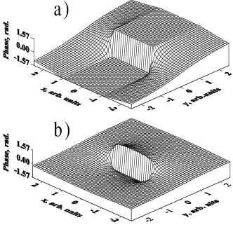
will be referred to as edge-screw (ES). In Eqs. (1)-(3) the quantity stands for the magnitude of the step portion of the dislocation, for its length, and and denote the transverse Cartesian coordinates parallel and perpendicular to the dislocation. Surface plots of the SS and ES phase dislocations are shown in Fig. 1a and 1b, respectively.
The formation of mixed phase dislocations was first identified by us in interferograms of decayed crossed one-dimensional DSSs in the presence of moderate saturation of the nonlinearity [27]. From our present point of view the classification [24] of such formation generated via an instability as an ES or SS phase dislocation cannot be definitive. Both distributions shown in Fig. 1 are characterized by the same maximal phase difference and dislocation length , but they differ in the rate at which the phase changes azimuthally at their ends. In the step-screw case this change rate is twice as high as in the edge-screw case. In another work [25] we found experimentally and confirmed numerically that in the interval the transverse steering velocity of an ODB of SS type is inversely proportional to . Because of the phase gradients across the edge portion of the dislocation the ES one starts ‘immediately’ steering. The step portion of the SS dislocation, however, is forced to steer by the outlying semi-helices. The process stabilizes after a propagation distance of the order of (see Figs. 2 and 3 in Ref. [24]), at a transverse velocity 2-3 times smaller than in the ES case. In view of this one more general statement holds: The transverse velocity of an ODB with mixed phase dislocation is inversely proportional to the absolute value of the azimuthal phase-change rate outward its ends. Therefore the identification of the type of ODBs generated as a result of an instability is not very reliable.
III Initial conditions for the model
The (2+1)-dimensional evolution of the ODBs in bulk homogeneous, isotropic and saturable NLM is described by the nonlinear Schrödinger equation
| (4) |
where . The transverse spatial coordinates are normalized to the initial dark beam width (, ), and the nonlinear propagation path length is expressed in units of Rayleigh diffraction lengths . Furthermore, is the nonlinear length, is the wave number inside the NLM, and the background beam intensity at its entrance isnormalized to that needed to form an 1D DSS of width (). In order to maintain the correspondence to the conditions in our previous experimental work [25, 27], where NLM with saturation was used, we adopted the refractive-index correction
| (5) |
with and . In a weak-signal approximation we took into account the bright-signal beam diffraction and the refractive-index changes it sees as induced by the ODB. In the NLM its evolution is described by
| (6) |
The coupling coefficient depends on the nature of the physical process of the optical nonlinearity (e.g. molecular orientation, electronic response of bound electrons, etc.) and on the experimental conditions (e.g. the polarizations of the waves). The numerical simulations presented in this work refer to the wavelength ratio and . The slowly-varying electric-field amplitudes of the ODBs were assumed to be -shaped and of the form
| (7) |
where for an SS, for an ES phase dislocation, and is the effective radial coordinate. In order to avoid any influence of the finite background beam of super-Gaussian form , its width was chosen to exceed the maximal ODB deflection at more than 10 times. The signal beam is assumed to be -shaped and equal in width to the ODB width . Its intensity is chosen hundred times weaker than , thus not disturbing the dark beams by cross-phase modulation. Equations (4) and (6) are solved numerically by modification of the beam propagation method over a grid.
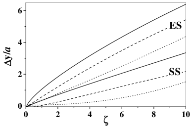
Figure 2 shows the deflection of ODBs with edge-screw (ES) and step-screw (SS) phase dislocations vs. the nonlinear propagation path length for (solid), (dashed), and (dotted), normalized to the initial ODB width . The difference between the transverse dynamics of the dark beams of different types is amazing. As already mentioned, it is due to the presence (in the ES case) or absence (in the SS case) of phase gradients across the one-dimensional portion of the dislocation at the entrance of the NLM. Besides by the type of the phase singularity, the transverse dynamics can be controlled in three possible ways [25]: by chaging ratio, the phase step and the background beam intensity. As it is seen in Fig. 2, changing the ODB length-to-width ratio gives an effective way to manipulate the ODB velocity. It is higher for the short and slower for the long dislocations. The long ones however could experience a transverse instability. More strongly pronounced is the increase of the velocity with decreasing the magnitude of the step portion of the phase dislocation [25], but we refrained from exploiting this. The reason is that during the steering process both types of ODBs inevitably become grey (and asymptotically disappear), which tends to destroy the coupler modeled. The numerical calculations performed showed similar but slightly weaker coupling efficiencies when the transverse deflection is controlled by than by . All data in this work refer to . Characteristic of the evolution of the ES phase dislocation is that it disturbs the background beam more weakly than the SS dislocation. In order to emphasize this, the number of gray-scale levels in the frames shown in Fig 3 are intentionally reduced in the same way. The data refer to and . The background beam intensity in this simulation is chosen to correspond to that of a 1D DSS (). The dashed line is intended to underline that the ES ODB is stronger deflected than the SS ODB.
The background beam intensity could be additionally used to controll the dynamics of the ODBs, even their deflection does not strongly depend on it [25]. The background beam intensity, however, influences substantially the transverse beam profile and the guiding properties of the induced waveguide. Better spatial confinement could be expected at higher intensities. Numerical simulations were made to confirm this statement. Depending on the type of the dislocation (ES or SS) the highest encoupling efficiencies were achieved for levels . Higher intensities tend to destroy the induced waveguide due to the strong deformation of the dark beam profile under saturation of the nonlinearity.
The main task of the numerical simulations presented bellow is to find the proper parameter range for and beam intensity in order to reach maximal coupling efficiency in the analyzed schemes for directional coupling.
IV One-directional coupler
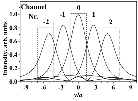
As a first step in this work we modeled the coupling of an input signal beam (pulse) to a desired output channel by optically induced waveguides. Figure 4 shows the positions and the forms of the weak signal beams guided by the corresponding dark one after a nonlinear propagation path length . Channel is assumed to be supported by an OVS [2, 3] with backround intensity , channels and by ODBs with SS phase dislocations of at , whereas channels and are considered to be induced by ODBs with ES phase dislocations with at . The change of the ODB steering direction in the NLM (i.e. the switching between channels with positive and negative numbers) is controlled by reversing the gradients of the screw portions of the dislocations. First, real implementation of this directional switching is feasible if there are reliable means to change the phase distributions of the ODBs. The electrically-controllable, multiply-active, computer-generated holograms developed [26] are well suited for doing that. Because of the time needed to reconfigure the hologram, the relatively rare redirection of the data streams addressed to a desired channel will be preferable. Second, the energy efficiency of the guiding and switching should be as high as possible at the lowest possible cross-talk between the channels. The imaginary information channels considered to be coupled to the exit of the NLM are assumed to be rectangle-shaped with a width (height) 1.5 (3.0) times the input signal-beam FWHM. In Fig. 4 the respective positions along the steering direction (the arrow in Fig. 3) are sketched as rectangles.
The results for the directional coupling and cross-talk efficiencies obtained as ratios of the transmitted energy in a particular channel to the total one are summarized in Table I. The ODB with an SS phase profile is assumed to couple the input channel to channel No. , whereas this with an ES dislocation redirects the input to channel . The maximal efficiencies for channels , , and to be expected are , , and , respectively. In most channels the cross-talk signal should remain well below . The ODB steering is accompanied by the creation of a leading dark wave and a trailing bright peak on the background beam (see Fig. 3 in Ref. [24]) which are more strongly pronounced in the SS case. The bright trailing peak pushes the signal beam stronger. This qualitatively explains the relatively high efficiency of the coupling to channels and . Because of the additional self-defocusing of this peak it appears more effective to address channels and by ES ODBs. If the out-lying channels are times larger than the input signal beam width , in the ES case the efficiency in coupling the signal to them can be increased by to . Due to the numerical discretization the overall accuracy in estimating the energies is within and the coupling efficiencies in the respective channels are correct to within .
We should note here that because of the saturation of the nonlinearity the width of the induced waveguide is larger than in the case of pure Kerr nonlinearity. If a Kerr medium is considered (i.e. ) the coupling efficiencies increase by , whereas the cross-talk coefficients become slightly weaker.
V Two-directional coupler
For addressing a desired channel from an imaginary array of information channels ( in this work) we used the squared-shaped channel configuration shown in Fig. 5. The data presented below refer to and channel width and height times the input signal beam FWHM. Best spatial confinement of the signal beams is achieved at times higher background beam intensity than that needed to form a 1D DSS of width . Besides being controlled by the type of the phase dislocation (screw, ES, SS), the ODB transverse velocity and deflection at the exit of the NLM are adjusted by the initial ODB length-to-width ratio ( in the SS case; and in the ES case; both at ). Let us denote the channels as , where and are the respective row and column indices. The central output channel , which is on axis with respect to the input one, is addressed by an OVS [2, 3], the side channels , , , and by ODBs with appropriately rotated SS phase dislocations, whereas signal beam coupling to each of the diagonal channels , , , and is performed by ODBs with ES phase dislocations rotated . The calculated coupling efficiencies are summarized in Table II. The maximal efficiencies for the direct channel , the neighboring channel , and the diagonal channel to be expected are , , and respectively, at cross-talk signals remaining well below . In Fig. 5 we composed grey-scale frames of the signal beams as located on the imaginary array of information channels considered. Coupling the input channel to information channel (by an ES ODB) should result in undesired but equal cross-signals in channels and (). If the input signal is coupled to channel the same should hold for channels and . The data obtained indicate that the discretization in our simulations leads to a maximal inaccuracy in estimating the coupling efficiencies that is within . If pure Kerr nonlinearity is considered the coupling efficiencies are to higher.
VI Conclusion
The numerical data on the nonlinear evolution of mixed step-screw and edge-screw phase dislocations under equivalent conditions shows an amazing difference between the transverse steering dynamics of SS and ES ODBs. Such odd dark beams are able to induce steering conduits for weak information beams (pulses) in bulk nonlinear media. Due to this two different schemes for directional coupling are proposed. The relatively high coupling and moderate cross-talk efficiencies in both of them provide a reasonable basis for further optimization and may open the way to constructing parallel reconfigurable all-optical logical elements.
Acknowledgements.
D.N. thanks Vrije Universiteit Amsterdam for the opportunity to complete part of the computational work at the facilities of the Laser Center, VU, Amsterdam. A.D. is grateful to the Alexander von Humboldt Foundation (Germany) for the award of a fellowship and the opportunity to work in the stimulating atmosphere of the Max-Planck-Institut für Quantenoptik (Garching, Germany).REFERENCES
- [1] G.A. Swartzlander, Jr., C.T. Law, Phys. Rev. Lett. 69, 2503 (1992).
- [2] A.H. Carlsson, J.N. Malmberg, D. Anderson, M. Lisak, E.A. Ostrovskaya, T.J. Alexander, and Yu. Kivshar, Opt. Lett. 25, 660 (2000).
- [3] C.T. Law, X. Zhang, and G.A. Swartzlander, Opt. Lett. 25, 55 (2000).
- [4] A.W. Snyder, L. Poladian, and D.J. Mitchell, Opt. Lett. 17, 789 (1992); A.W. Snyder and A.P. Sheppard, Opt. Lett. 18, 482 (1993); A.W. Snyder, S.J. Hewlett, and D.J. Mitchell, Phys. Rev. Lett. 72, 1012 (1994).
- [5] A.A. Zozulya and D.Z. Anderson, Phys. Rev. A 51, 1520 (1995).
- [6] M. Shih, Z. Chen, M. Mitchell, M. Segev, H. Lee, R.S. Feigelson, and J.P. Wilde, J. Opt. Soc. Am. B 14, 3091 (1997).
- [7] M. Taya, M.C. Bashaw, M.M. Fejer, M. Segev, and G. C. Valley, Phys. Rev. A 52, 3095 (1995).
- [8] Z. Chen, M. Shih, M. Segev, D.W. Wilson, R.E. Muller, and P.D. Maker, Opt. Lett. 22, 1751 (1997).
- [9] M. Morin, G. Duree, G. Salamo, and M. Segev, Opt. Lett. 20, 2066 (1995).
- [10] Z. Chen, M. Mitchell, M. Segev, T.H. Coskun, and D.N. Christodoulides, Science 280, 889 (1998).
- [11] L. Friedrich, G.I. Stegeman, P. Millar, C.J. Hamilton, and J.S. Aitchison, Opt. Lett. 23, 1438 (1998).
- [12] Y. Li, Y. Chen, and R.R. Alfano, Opt. Lett. 16, 438 (1991).
- [13] Yu.S. Kivshar, J. Christou, V. Tikhonenko, B. Luther-Davies, and L. M. Pismen, Opt. Commun. 152, 198 (1998).
- [14] D. Rozas, C.T. Law, and G.A. Swartzlander, Jr., J. Opt. Soc. Am. B 14, 3054 (1997).
- [15] B. Luther-Davies, R. Powles, and V. Tikhonenko, Opt. Lett. 19, 1816 (1994).
- [16] D. Neshev, A. Dreischuh, M. Assa, and S. Dinev, Opt. Commun. 151, 413 (1998).
- [17] J. Christou, V. Tikhonenko, Yu.S. Kivshar, and B. Luther-Davies, Opt. Lett. 21, 1649 (1996); see also I.V. Basistiy, V.Yu. Bazhenov, M.S. Soskin, and M.V. Vasnetsov, Opt. Commun. 103, 422 (1993).
- [18] B. Luther-Davies and Y. Xiaoping, Opt. Lett. 17, 496 (1992).
- [19] M. Taya, M.C. Bashaw, M.M. Fejer, M. Segev, and G.C. Valley, Opt. Lett. 21, 943 (1996).
- [20] D. Neshev, A. Dreischuh, S. Dinev, and L. Windholz, J. Opt. Soc. Am. B 14, 2869 (1997).
- [21] A. Dreischuh, V. Kamenov, and S. Dinev, Appl. Phys. B 63, 145 (1996); V. Kamenov, A. Dreischuh, and S. Dinev, Phys. Scripta 55, 68 (1997).
- [22] Yu.S. Kivshar and V.V. Afanasjev, Opt. Lett. 21, 1135 (1996); see also W. Krolikowski, X. Yang, B. Luther-Davies, and J. Breslin, Opt. Commun. 105, 219 (1994).
- [23] A.V. Mamaev, M. Saffman, and A.A. Zozulya, Phys. Rev. Lett. 78, 2108 (1997).
- [24] A. Dreischuh, G.G. Paulus, F. Zacher, I. Velchev, Appl. Phys. B 69, 113 (1999).
- [25] A. Dreischuh, D. Neshev, G.G. Paulus, and H. Walther, “Experimental generation of steering odd dark beams of finite length,” J. Opt. Soc. Am. B (submitted); e-print: nlin.PS/0003011.
- [26] C. Slinger, P. Brett, V. Hui, G. Monnington, D. Pain, and I. Sage, Opt. Lett. 22, 1113 (1997).
- [27] A. Dreischuh, G.G. Paulus, and F. Zacher, Appl. Phys. B 69, 107 (1999).


| Channel | -2 | -1 | 0 | 1 | 2 | Energy |
|---|---|---|---|---|---|---|
| guiding by | losses | |||||
| OVS | 0.3 | 9.5 | 74.7 | 9.5 | 0.3 | |
| SS ODB | 0.5 | 0.2 | 9.6 | 70.7 | 5.6 | |
| ES ODB | 52.2 | 14.1 | 1.4 | 1.6 | 0.8 | |
| (55.9) |
| Channel | Energy | |||||||||
|---|---|---|---|---|---|---|---|---|---|---|
| guiding by | losses | |||||||||
| OVS | 1.3 | 7.3 | 1.3 | 7.3 | 61.6 | 7.3 | 1.3 | 7.3 | 1.3 | 4.0 |
| SS ODB | 0.2 | 2.4 | 12.6 | 0.1 | 6.1 | 49.6 | 0.2 | 2.4 | 12.6 | 13.7 |
| ES ODB | 47.1 | 5.5 | 0.7 | 5.5 | 0.3 | 0.5 | 0.7 | 0.5 | 0.5 | 38.6 |