High Level Tracker Triggers for CMS
Abstract
Two fast trigger algorithms based on 3 innermost hits in the CMS Inner Tracker are presented. One of the algorithms will be applied at LHC low luminosity to select B decay channels. Performance of the algorithm is demonstrated for the decay channel . The second algorithm will be used to select -jets at LHC high luminosity.
keywords:
Triggering , B-physics , Pixel detectors , CMSPACS:
29.40.Gx1 Introduction
The collision rate at LHC [1] is foreseen to be 40MHz. To handle such rates a powerful DAQ system and also fast and efficient trigger algorithms are needed. The CMS Collaboration [2] has chosen a trigger scheme based on two components: a hardware Level 1 Trigger and a software Level 2 Trigger. As any collider detector, CMS is composed of tracker, calorimeter and muon systems. At Level 1 the information from the muon and calorimeter systems is used. At Level 2, called Higher Level Trigger (HLT) in CMS, also the tracker contributes to the event selection.
The CMS tracker system [3] is based on two technologies: 1) silicon pixel detectors, which are closest to the beam, provide 3-D hits used for vertexing, and 2) silicon strip detectors placed at larger radii are used for pattern recognition and track reconstruction. The amount of information coming from the pixel detector is about 10% of the full tracker, hence it is reasonable to use it at the beginning of the HLT algorithms. In this article we present track reconstruction algorithms based on 3 innermost tracker hits. At low LHC luminosity (), when only two pixel layers are foreseen, the third hit is taken from the lowest radius strip detector layer. At high luminosity () the algorithm is based purely on the pixel detector.
2 Detector layout
The results shown here were obtained with a full GEANT based simulation of the CMS detector using the CMSIM [4] and ORCA [5] software packages. The CMS inner tracker layout used in the simulation will be briefly mentioned below, more details can be found in Ref.[3, 6, 7, 8]. The pixel detector consists of three barrel layers located at mean radii 4.3 cm, 7.2 cm and 11.0 cm. The 52 cm long pixel barrel is supplemented by two endcap disks on each side. With this configuration the pixel detector provides 3 hit coverage up to rapidity . For low luminosity only two barrel layers will be installed giving 2 pixel hits up to . The silicon strip barrel layer used in our reconstruction algorithm is 89.2cm long and is located at a mean radius of 23.5cm
3 The triggering scheme
The goal of the CMS trigger system is to reduce the event rate from down to that will be stored for off-line analysis. The DAQ architecture is designed in such a way that it should sustain maximum output rate of Level 1 trigger of and provide HLT acceptance of about . As mentioned in the Introduction the Level 1 trigger decision is based on the muon and calorimeter systems, at HLT the tracker information will be added. Even if the full detector information is accessible at HTL, fast algorithms which select event topologies of interest and use partial information should be applied first.
4 Track and vertex reconstruction
Two algorithms based on the track reconstruction from the 3 innermost tracker layers will be discussed below, both start from the two innermost pixel layers. For the hit the first strip layer is used in one algorithm, the second algorithm uses the third pixel layer.
4.1 Track reconstruction using the pixel detector
The pixel track finding algorithm has been explained in Ref.[9], here only the most important details will be given. It’s three essential steps are shown in Fig. 1. Pixel hit pairs from the first two layers (barrel+barrel or barrel+endcap) are matched in and to establish track candidates. The cuts are optimized for a minimum track transverse momentum () of and permit a maximum impact parameter in of . In the plane the hit pairs have to point to a region in within of the LHC luminous region.
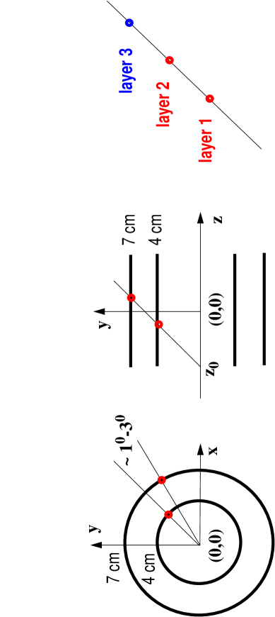
Valid pixel pairs are matched with a pixel hit forming a track candidate. Using these tracks a list of primary vertices (PV) is formed at z values where at least 3 tracks cross the z axis. Tracks which do not point to any PV candidate are erased. Due to the detector overlaps in the direction for some Monte Carlo tracks more than one track candidate is found. Track pairs which share pixel hits and are closer than from each other are identified. A cleaning procedure then erases one of the tracks in each pair.
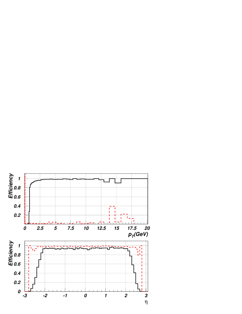
The track finding efficiency is illustrated in Fig. 2 where the efficiency (the ratio of reconstructed to Monte Carlo tracks) is shown as a function of the track and rapidity. Only reconstructed tracks which have all 3 hits correctly assigned are counted and the fraction is normalized to all Monte Carlo tracks which are within the full acceptance of the pixel detector. The plotted efficiency is for high luminosity LHC events in the presence of minimum bias pile-up interactions (on the average 20). However, the comparison is done for the signal tracks only, that is tracks originating from the minimum-bias events are ignored. In the upper part of Fig. 2 the reconstruction efficiency and the ghost rate is shown as a function of . The lower part shows that the efficiency (for tracks with ) is flat within the rapidity coverage of the pixel detector. The solid curve shows the absolute efficiency and the dashed curve the algorithmic efficiency (normalized to the number of tracks with 3 pixel hits). For all event types considered in our HTL studies the absolute track finding efficiency for tracks above is about 90%. The algorithmic efficiency is between 93% and 95% and the fraction of ghost tracks is typical between 5% and 8%.
Obviously the track parameters, fitted with 3 points only, are much inferior to the full tracker resolution. The reconstructed track’s direction is good, the resolution in the direction being and in the direction . The measurement however, is poor, mainly because of the small radius of the last hit (11 cm). For tracks this resolution is about 7%, but for it reaches 20% (see Ref.[9] for more details). The curvature of the tracks is sufficient to distinguish the track sign with 100% efficiency up to of .
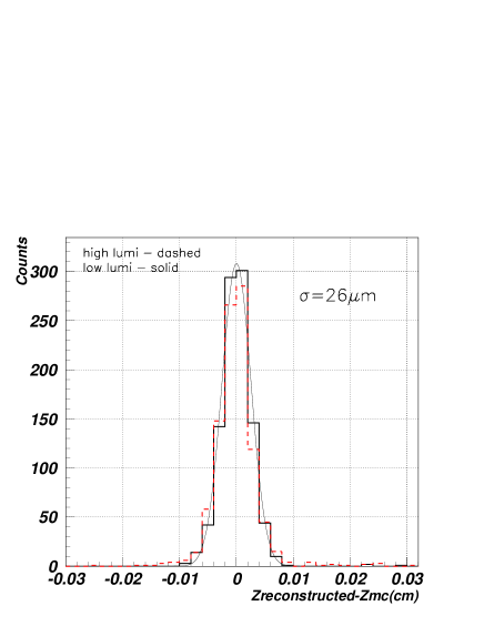
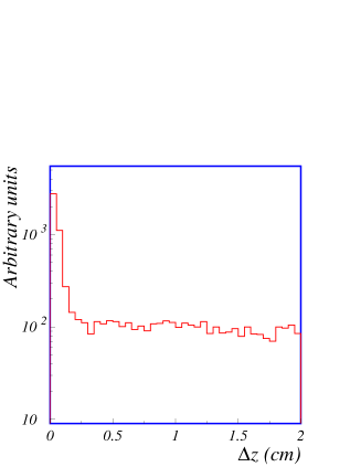
The primary vertex candidates found during the track finding stage are reanalyzed. Only PVs with at least 3 valid tracks are kept and the position of each vertex is estimated as the mean value of the z impact parameters of all tracks assigned to it. In addition to the main “signal” PV, on the average more PVs per event are found at high luminosity. The “signal” PV is usually found with a high accuracy of better than 50 m. This is shown in Fig. 3 where the difference in the z position of the reconstructed vertex and the Monte Carlo vertex is plotted. The efficiency of this algorithm is high, for the HLT event samples the “signal” PV is always found with an efficiency of better than 95%.
4.2 Reconstruction using the pixel detector and one strip layer
This algorithm is similar to the one discussed in section 4.1. Since the algorithm is developed to trigger on exclusive B meson decays, selection criteria listed below are optimized for such decays. Below we describe it in more detail.
-
1.
Any pair of hits from two separate pixel layers are connected with a straight line in the transverse plane. We utilize the fact that the tracks we want to reconstruct are relatively stiff () and the lever arm is small (). Then the impact parameter (IP, the distance from the line to the primary interaction point in the transverse plane) is calculated. If it is less than , the two hits create a track candidate.
-
2.
Extrapolating the straight line that connects two selected hits to the third (strip) layer in the plane, the expected position () of a third hit is calculated. If there is a reconstructed hit with its coordinate close to , , it is taken as the third hit of the track candidate. The momentum and the charge of the track is determined.
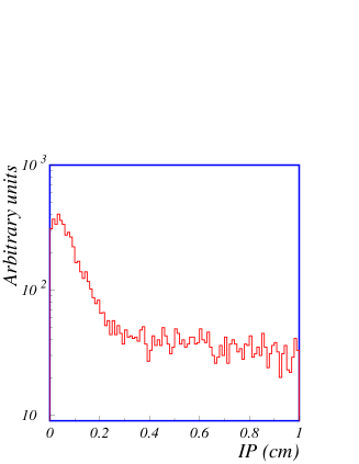
In Fig. 4 we show the and distributions for decay (1) to illustrate the above cuts. If the transverse momentum of the reconstructed track is greater then it is accepted for further analysis.
5 B-physics triggers
The Level 1 B physics trigger in CMS is mainly based on the muon system (the single muon trigger rate is assumed to be 10kHz). At the Level 2 information from the muon and calorimetric systems will be reanalyzed with fine granularity and more sophisticated algorithms. However, soft products of B decays usually do not manifest themselves in the calorimeters and more precise calculation of the trigger muon momentum can suppress the rate by only a factor of 2. Thus, one needs to apply further selection algorithms which are specific to B decays, e.g. reconstruction of B decay products (tracks) and calculation of invariant masses of intermediate resonances if any.
The idea of using only 3 innermost hits at HLT to select the exclusive B decay modes is based on the observation that the momentum resolution provided by these 3 hits is only a few times worse than that obtained with the full tracker. Fig. 5 shows the transverse momentum resolution in percentage versus the number of continues hits used for track reconstruction. Two distributions represent results for tracks of 1 and 10.
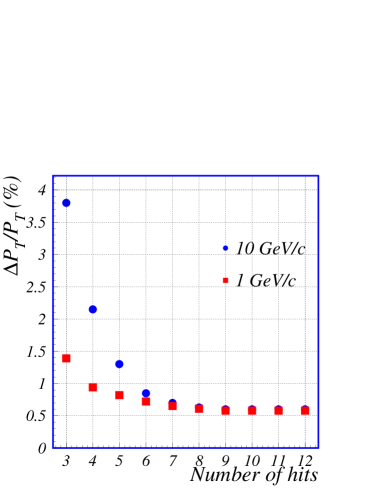
One can see that for tracks with the transverse momentum resolution obtained with 3 hits is about 1.5%, 2 times worse than with the full tracker.
The decay mode (and its charge conjugate)
| (1) |
has been chosen as a benchmark. Only the decay chain is triggered at this stage which allows us to select also the following decay modes of the B meson:
| (2) |
where = , , and .
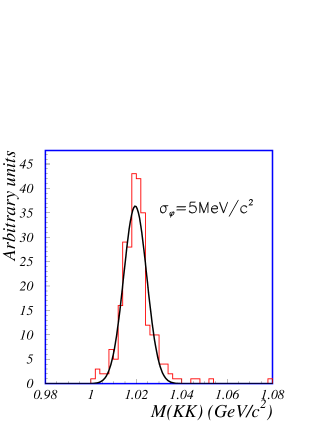
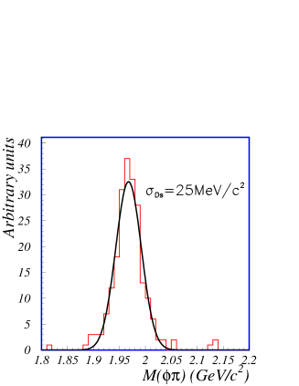
Applying the reconstruction algorithm discussed in Section 4.2 we obtain the momentum and the charge for each reconstructed track. To trigger the decay modes (1,2) we reconstruct all tracks with and then find all and candidates by trying different track combinations. An event is selected if two conditions are fulfilled. Firstly, that there are two oppositely charged tracks close to each other (), and their invariant mass (assuming they are kaons) is compatible with the mass, . Secondly, there is a third track in the cone around the reconstructed candidate and the invariant mass of this candidate and the third track (assuming it is a pion) agrees with the mass, . Mass cuts have been defined based on expected mass resolutions shown in Fig. 6 for the decay mode (1): and .
The proposed algorithm reduces the single muon trigger rate by factor of 30 while providing a signal efficiency of about 75%. The fraction of ghost tracks is relatively small (about 10%). Further reduction of trigger rate will be based on more strict cuts using the full CMS tracker capability to reconstruct exclusive B decays.
6 Tau trigger
The “pixel” trigger proposed here is an example of a tracker HLT application which uses only the pixel data. As signal events we used SUSY Higgs bosons decaying into two leptons with two hadronic jet(s) in the final state. The main background for such events are QCD 2-jet events in the range 50-230 GeV/c.
More details about the algorithm and the event samples used in the simulation
can be found in Ref.[10].
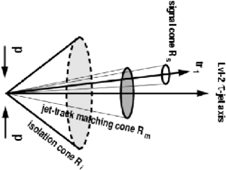
The HLT pixel algorithm is based on track isolation criteria and is
schematically shown in Fig 7.
The -jet direction is defined by the calorimeter trigger.
All track candidates in the matching cone around the jet direction and
above the cut are considered in the search for signal tracks,
that is tracks which originate from the hadronic decay.
The track with the highest is declared the “leading” track
( in Fig. 7).
Any other track which is in the narrow cone
around is also assumed to come from the decay.
A larger area is now searched for tracks above the cut.
If no tracks are found in the cone, except the ones which are already
in the cone, the isolation criteria is fulfilled and the jet is
labeled as a -jet.
The narrow signal cone around the “leading” track is needed
in order to trigger on 3 prong decays in addition to 1 prong.
Typical values of the cuts used above are : =0.05, =0.10,
=0.35, c and .
The algorithm works very well at low luminosity. At high luminosity, however, it’s efficiency becomes small (about 50%) due to the large number of tracks originating from the pile-up interactions. The efficiency is improved by using the PVs information. The vertex of the leading track is assumed to be the “signal” PV (this assumption is correct for 99% of events). Once the “signal” PV is defined only those tracks which were assigned to it are considered in the isolation criteria. This approach increases the efficiency of our algorithm at high luminosity to the same value as at low luminosity.
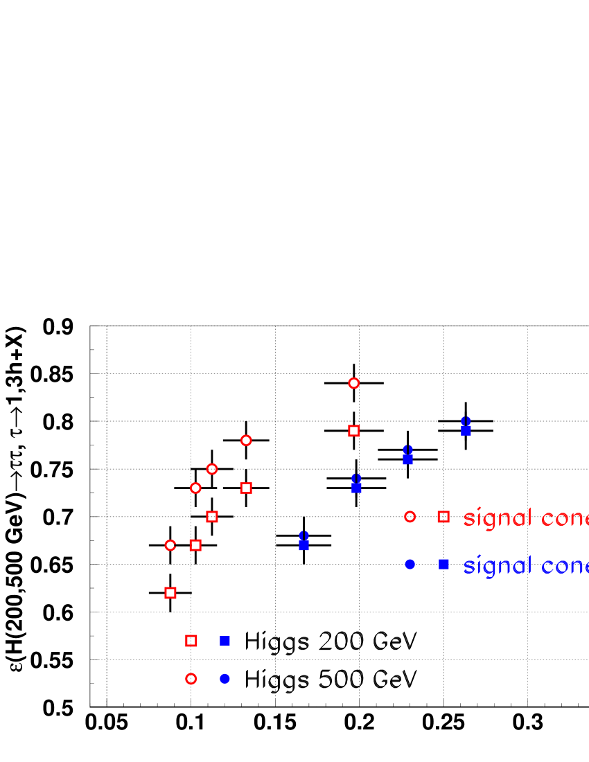
The variation of the QCD 2-jet background and the Higgs signal efficiency with the change of the isolation cone size is shown in Fig. 8 for Higgs mass of (full squares) and (full circles) and for two signal cone sizes =0.05 and 0.10. The points from left to right correspond to the following values of = 0.50, 0.40, 0.35, 0.30 and 0.20. One can see that a rejection factor of 5 (for the 0.10 signal cone) can be reached with an efficiency 75%. A higher background rejection of 10 (for the 0.05 signal cone) can be achieved but at a price of the efficiency being dependent on the Higgs mass.
7 Conclusions
Fast HLT algorithms for B physics decays and -jets have been developed based on the CMS pixel detector and the innermost strip layer. The key feature of these algorithms is track reconstruction based on 3 hits only. Track parameters are calculated based on a simple helix approach. It is demonstrated that one can obtain high track reconstruction efficiency ( 90%), very accurate primary vertex position in the dimension () and a good momentum resolution (1%4%) for tracks with . High reduction of background rates (about 30 for B physics channels and 5 for Higgs) with a good signal efficiency of 75% are achieved.
References
- [1] The LHC Conceptual Design, CERN/AC/95-05(LHC).
- [2] The CMS collaboration, CMS Technical Proposal, CERN/LHCC 94-38 1994.
- [3] The CMS collaboration, CMS Tracker Technical Design Report, CERN/LHCC 98-6 1998.
- [4] CMS Simulation Package CMSIM, http://cmsdoc.cern.ch/cmsim/cmsim.html
- [5] Object Oriented Reconstruction for CMS Analysis, CMS Internal Note 1999/001 and http://cmsdoc.cern.ch/orca/
- [6] M. Lenzi, Vertex2000, Nucl. Inst. and Meth. A 473(2001)31.
- [7] M.Angarano, The silicon strip tracker for CMS, to be published in Vertex2001 Conference Proceeding.
- [8] S.Schnetzer, The CMS pixel detector, to be published in Vertex2001 Conference Proceeding.
- [9] D. Kotlinski, CMS Internal Note 2000/22.
- [10] D. Kotlinski, R. Kinnunen and A. Nikitenko, CMS Note 2001/017.