Higgs: KeV precision and CP violation
The prospects for a muon collider operated as a Higgs factory are reviewed. The large muon mass means that the s-channel Higgs production mechanism is available, and simultaneously suppresses bremsstrahlung so that the beam energy spread can be kept to the MeV level required to exploit this. Thus this is the only machine which can make a direct scan over the Higgs resonance, and make an extraordinary mass measurement. Further possibilities such as a scan of the H and A of supersymmetry and CP violation are also mentioned.
1 Reminder of muon colliders
The muon collider is the only way of pushing the energy frontier beyond the region of applicability of electron colliders, while retaining the advantages of a point-like projectile. The mass is 200 times that of an electron, so storage rings behave like those of proton machines while a beam energy spread as low at may be possible, which means that narrow resonances can be scanned. The lack of beamstrahlung means that thresholds are clean, and the energy can be measured to via g-2.
This measurement of the Higgs mass benefits from the coupling , which gives a cross-section for s-channel production 40,000 times the electron equivalent. This allows a direct scan, giving the mass and width. This possibility depends upon a Higgs below the W threshold, so it is encouraging that EW fits and direct observation appear to favour this. Indeed one study found 115 GeV as the optimal Higgs mass for a muon collider.
The disadvantage of a muon collider is of course the muon lifetime of 2.2 s, which means that muon production and cooling has to be performed on a similar time-scale. Furthermore the electrons from the muon decay will constitute a serious detector background. Both these difficulties mean that we wish to maximize the luminosity per amp of muon current, which implies cooling the beams as much as possible.
The decay of a high energy muon beam provides an ideal source of neutrinos for the study of the neutrino mixing. Such a project is simpler than a muon collider, particularly with regard to cooling, and it will therefore probably be built first. Its construction will bring advances in the techniques required for the collider, and it will both serve as an important proof of principle and probably be directly used in the collider construction.
2 Overview of the accelerator components
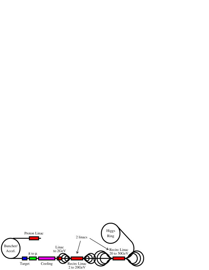
Figure 1 shows the essential components of a muon collider. A proton source provides power in the megawatt range on a target, which is optimized for pion production. The pions are allowed to decay to muons, which are then rapidly cooled with ionization cooling. They are then accelerated to the required energy, probably in a recirculating linear accelerator and fed into a collider ring. The whole procedure will repeated many times per second.
2.1 Proton driver
The proton source must provide a large amount of power, of the order of four megawatts at an energy large enough to produce pions copiously. The exact energy of the beam is under discussion, with possibilities ranging from 2.2 GeV to 24 GeV, and the HARP experiment at CERN is measuring pion production and will be important in making this choice. The pulse length must be order 1 ns or so, in order to reduce the phase space of the outgoing muons, but there is no advantage in reducing it below this, because the time jitter introduced by the to decay is of the same order.
The proton driver can either be a linac or a rapid cycling synchrotron. The CERN proposal for a Superconducting Proton Linac is the best example of the former. This accelerator would re-use the LEP superconducting cavities, supplemented by new cavities designed to work with lower velocity particles. It could in principle deliver even more than 4 MW, but the energy is limited to 2.2GeV. Furthermore it needs bunching and compression if the small time structure is to be achieved.
A synchrotron solution would be able to operate at higher beam energy, and this has the advantage that less protons are required, and the phase space density requirements are easier. Thus it may be more suitable for delivering a few high intensity muon pulses which are required for a collider, rather than many small ones which might be satisfactory for a muon neutrino source.
2.2 Target and pion collection
To optimize the muon rate, it is important to collect as large a fraction of the pions produced as possible. The peak kinetic energy is rather low, or order of the pion mass, independent of the beam power, because most pions are produced through secondary interactions. Such pions cannot penetrate much material. However, it is important to use a large fraction of the energy in the proton beam, and this requires a thick target. The solution is to use a rod-shaped target, so that pions with any significant are emitted from the sides of the target. A radius around 5mm seems to be optimal for a fairly dense target.
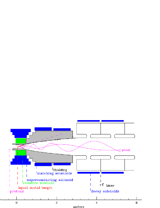
The target is either inside a solenoidal magnetic field or in front of a magnetic focusing horn, which serve to confine the pions into a drift volume. If a solenoid is used, as shown in figure 2 the field will be of order 20 Tesla, which encloses pions with a transverse momentum below 225 MeV within a radius of 8 cm.
The target must be able to cope with the proton power of perhaps 4 MW. In such a small target this gives a very large heating, and while solid solutions are still under active investigation, the preferred design is a liquid metal jet. The jet is of course a conductor, and it remains to be shown that it can be injected into such a strong magnetic field without disruption. The jet will certainly be disrupted by the beam, but reforms in around 20 ms, ready for the next proton pulse. The proposed system has a difficult combination of magnetic fields, heat transfer, mechanical stress and radiation exposure.
2.3 Decay and phase rotation
The pions must now be allowed to decay to muons which are to be cooled and accelerated. These later steps require that the momentum spread of the beam be reduced so that the bunch does not diverge. The simplest way of doing this in principle is to drift for some tens of meters, during which the decay occurs and a correlation between velocity and arrival time is created. A matched phase-rotating RF system can then be employed to decelerate the first arriving fast muons and accelerate the slowest ones. That then gives a long bunch with relatively uniform energy.
A more sophisticated solution is to chop the bunch into several sub-bunches which are differentially accelerated, as above, but also given different paths so that they all arrive at the next stage at the same time. The combination of the sub-bunches is by no means easy, and it will inevitably increase the transverse beam emittance, but this is relatively easy to reduce afterwards with ionization cooling.
2.4 Cooling
The rapid muon decay means that traditional cooling techniques are too slow, but fortunately ionization cooling seems to provide an answer. The principle is that muons loose energy when they pass through matter, and they can be re-accelerated in the longitudinal direction. This provides a net reduction in the transverse momentum, although not longitudinally.
| (1) |
Where is the emittance in one transverse direction , is the betatron function of the absorber and is the radiation length. The first term corresponds to ionization cooling, and the second to warming due to multiple scattering. There is an equilibrium when
| (2) |
The optimal cooling therefore calls for minimum . This is clear: the minimum in the beta function corresponds to a maximum in the beam divergence, and at this point the contribution from multiple scattering is least important. However, we also wish a material which maximizes the product of radiation length and , which will be achieved for low Z. This product (evaluated at the minimum of the curve), is 253 for Hydrogen, while for lithium, which is easier to handle and a conductor, it is 131. There is thus almost a factor of two advantage in using hydrogen, and heavier elements are correspondingly worse. Another possibility is LiH, which has of 137, and could be a useful for an absorber with a complex shape.
For the first stages of cooling the beam is large, and the ultimate limit is not important, and hydrogen is a good choice of material. For the final cooling stages it may be that higher fields can be created by the use of a lithium lens, with kAmps of current flowing through it, and that a low be more advantageous then using hydrogen.
Cooling is required in both transverse and longitudinal directions, but the latter cannot be achieved by ionization cooling directly. Instead it is necessary to exchange emittance between transverse and longitudinal components, whilest cooling transverse. This is usually thought to be done using a magnetic field to differentially deflect them beam, and then an absorber whose thickness varies with position so that a greater thickness is seen by the higher energy particles. However, detailed designs are difficult, as scatterings and imperfections tend to warm the beam.
A promising recent development is the ring coolers, an example of which is shown in figure 3 a). These seem to be provide genuine six dimensional cooling despite allowing for windows and tails of scattering. However, a ring needs fast kickers to inject and eject the beam, and at present there is no space available for these.
A summary of cooling desired and designed can be seen in figure 3 b). There are many gaps in the chain, but the ring coolers and lithium lens devices do seem to be pieces of the overall cooling scheme.
2.5 Acceleration and collider
The acceleration is not in principle a great difficulty. To get to say 57.5 GeV per beam for a Higgs factory will require linear accelerators, but these can be recycling, either in a racetrack or dog-bone design. The latter seems to offer the best price for a specified performance, as the same accelerating cavities are used by the muons in both directions, meaning that half as much RF is required.
| CoM energy | 3 TeV | 400GeV | 100GeV | |
| p power, (MW) | 4 | 4 | 4 | |
| (Hz) | 32 | 240 | 960 | |
| /bunch | ||||
| circumference (m) | 6000 | 1000 | 350 | |
| (T) | 5.2 | 4.7 | 3 | |
| 785 | 700 | 450 | ||
| (%) | 0.16 | 0.14 | 0.12 | 0.003 |
| 6-D (m3) | ||||
| RMS ( mm-rad) | 0.05 | 0.05 | 0.085 | 0.29 |
| (cm) | 0.3 | 2.6 | 4.1 | 14.1 |
| (cm) | 0.3 | 2.6 | 4.1 | 14.1 |
| (m) | 3.2 | 26 | 86 | 294 |
| Luminosity, () | ||||
The collider rings radius should be minimized to increase the number of turns the muons make before they decay. For average dipole fields of 5 Tesla, 750 effective turns are made. A 115 GeV collider could have a circumference of around 350 m, and a 3 TeV machine would be only 6 km in circumference.
However the dipoles do have to cope with the electrons coming from the muon decay, which, due to their lower momentum are bent onto the inner wall of the collider. It may be that a substantially open design, allowing the electrons to emerge from the superconducting magnet region is optimal, but in any case some cm of shielding will be required. This is why a 5 Tesla field is considered, rather than the higher values achieved for LHC tests.
One of the great advantages of the muon collider is the energy precision and calibration. Due to the reduction of bremsstrahlung a bunch with a very small energy spread can be maintained, and the two 100 GeV machines in table 1 differ only in this spread. This is required if a narrow resonance like the Standard Model Higgs around 115 GeV is to be scanned.
The energy (and its spread) can be measured very accurately, using the muons spin precession. This is the same measurement as formed the basis of the LEP calibration, but is much easier because the muon decay to electron is self analyzing, and allows the measurement of the polarization on every turn, and this means that each fill can be calibrated with a precision given by g-2. Also the energy spread can be extracted from the dilution of the polarization with time.
2.6 Detector
The detector suffers from one major difficulty - the background from electrons coming from the muon decay. These will spill into the active volume creating fake tracks and noise hits, and at high energy Bethe-Heitler muons will also be created, which are too difficult to stop. Suppression of the decay electrons will rely upon a complex masking scheme, and current designs reduce the noise levels to about the same as in LHC detectors. Unfortunately this does include a mask in the low angle region, probably up to 20o to the axis, which will reduce the physics performance in the forward region. This leads to similar solutions being suggested: pixel detectors starting at a few cm radius appear to be able to cope with the noise.
The calorimeter may suffer from the Bethe-Heitler muons, and it seems that a segmented design, where these can be recognized by their orientation, will be required.
3 Higgs Physics
A sample scan of the Higgs resonance is shown in figure 4 a). The Higgs needs to be found before the collider can be built, and its mass known. However, if the mass information is accurate to only 60 MeV, as seems likely, then it will take a year to scan this region and locate the resonance. After a couple more years the width will be known to 1 MeV and the mass error is at present limited by g-2 to about 100 KeV.
The Higgs width is a very interesting test of the model, as it is uniquely fixed (given the mass) in the Standard Model, but differs in extensions such as supersymmetry. If the LHC and a linear collider information can exclude the A of the MSSM (for ) below 400 GeV, one year with a muon collider will extend this to 900 GeV, and further with more luminosity.
If the scan does show something more consistent with the MSSM than the SM we can immediately constrain the model parameters. Figure 4 b) shows the improvement that the muon collider would make compared with the information likely to be available from the LHC and Linear Collider. The plots on the left give the improvement from a very modest 100 pb-1, while those on the right show what could be learnt in 10 fb-1 were available. No theoretical errors have been allowed for; these are currently substantial.
3.1 Scan of H and A in the MSSM
If the standard Model Higgs weighs more than twice the W mass then its increased width due to decay to W pairs means that the peak cross-section is too small for a direct scan to make sense. This is not however true for the heavier Higgses of supersymmetry, and it will be desirable to make a direct scan of these resonances as well.
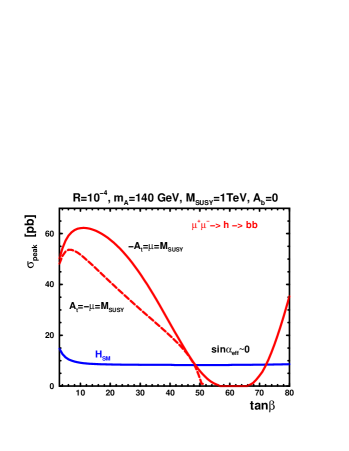
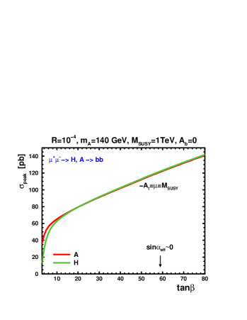
The coupling of the muon to the different Higgses depends upon the Higgs mixing angles, for example is proportional to , but figure 5 makes it clear that if the lightest is suppressed the heavier Higgses will be enhanced. Thus the MSSM presents an even more interesting picture for a muon collider.
The mass splitting of the H and A is rather small, and it is unlikely that any other machine can resolve them as separate resonances. What value it is will depend upon the other parameters, but it is clear from figure 5 that the cross-sections can be similar to or larger than the , and if the widths are relatively large the collider luminosity can be increased.
3.2 CP violation
One very interesting area for study is the CP properties of the Higgs system. In the MSSM, for example, the h, H and A can in general be mixed, and so it is important to measure this. If the second Higgs doublet is not so heavy that it decouples then the lightest physical Higgs state may well have mixed CP. In this case there will be very interesting studies, because production of say quark pairs can proceed through , Z or h exchange, and so interference can give rise to observable effects. The heavier states are in general more sensitive, because their masses are similar and mixing is more likely.

Figure 6 shows one analysis based on direct CP violation. Note that for these parameters the introduction of CP violation generates a mass splitting of the H and A which was not present without.
4 Summary
The muon collider operated as a Higgs factory will give the definitive measurement of the Higgs mass and width. There are also unequaled opportunities for establish the CP nature of the system. There is a lot of work to be done before a machine can be constructed, but no insurmountable obstacles have been identified. In the meantime the neutrino factory developments will push forward the technology.
References
References
- [1] C. Ankenbrandt et al., Status of Muon Collider Research and Development and Future Plans, Phys. Rev. ST Accel Beams 2,081001.
- [2] B. Autin et al., Prospective study of muon storage rings at CERN, CERN 99–02, (1999).
- [3] LEP Electro-weak working group, http://lepewwg.web.cern.ch/LEPEWWG/
-
[4]
P.I. Kemenes, LEP Higgs working group report to LEPC, November 2000.
http://lephiggs.web.cern.ch/LEPHIGGS/talks/pik_lepc_nov3_2000.ps -
[5]
Status of the HARP experiment,
CERN-SPSC/2000-029 (2000)
http://harp.web.cern.ch/hard/Documents/status_report_Oct2000.ps - [6] R. Garoby, M. Vretenar, Status of the Proposal for a Superconducting Proton Linac at CERN, CERN/PS/99-064 (RF), (1999).
- [7] J.R.J. Bennett, A High Power Radiation Cooled Rotating Toroidal Target for Neutrino production, Jan 2000. http://nicewww.cern.ch/ nfwg/nufactwg/ECFA/cern19jan00.ppt
- [8] V. Balbekov, Ring Cooler Update, http://www-mucool.fnal.gov/mcnotes/muco189.ps, Feb 2001.
- [9] R. Fernow, 3rd Higgs Factory workshop, UCLA, March 2001
-
[10]
TESLA Technical Design Report, March 2001.
http://tesla.desy.de/new_pages/TDR_CD/start.html - [11] G. Weiglen, Theoretical implications of the possible observation of Higgs Bosons at LEP, XXXXVI rencontres de Moriond, March 11-17, 2001, http://moriond.in2p3.fr.
- [12] B. Autin et al., Continued study of muon storage rings at CERN, CERN Yellow report, to be published in 2001.
- [13] E. Asakawa, S.Y. Choi and J.S. Lee, Phys. Rev. D62 (2000) 115005.