TTP00-12
NIKHEF-2000-017
hep-ph/0007221
July 2000
Parallelizing the Symbolic Manipulation Program FORM
Part I: Workstation Clusters & Message Passing
D.Fliegner†, A.Rétey†, J.A.M. Vermaseren‡
†Institut für Theoretische Teilchenphysik,
Universität Karlsruhe, D-76128 Karlsruhe, Germany
‡NIKHEF, P.O. Box 41882, 1009 DB, Amsterdam, The Netherlands
Abstract
The present paper is the first of a series of papers reporting on the parallelization of the symbolic manipulation program FORM on different parallel architectures. Part I deals with workstation clusters using dedicated network hardware and the messages passing libraries (MPI and PVM). After a short introduction to the sequential version of FORM a detailed analysis of the different platforms used is given and the structure of the parallel version of FORM is explained. The forthcoming part II will describe the parallelization of FORM on SMP (symmetrical multi-processing) architectures.
keywords: symbolic manipulation, computer algebra, high energy physics, perturbation theory, FORM
1. The Sequential Version of FORM
1.1 Introduction
FORM is a program for symbolic manipulation of algebraic expressions specialized to handle very large expressions of millions of terms in an efficient and reliable way. Although it supplies a programming language that allows for the formulation of a wide area of symbolic algorithms it is currently mainly used for computations in high energy physics. Especially in the field of perturbative calculations of higher order corrections to quantum field theoretical quantities (the so-called multi loop calculations) FORM has become a standard tool.
A systematic introduction to the FORM programming language is of course far beyond the scope of this paper and the reader is referred to [1]. Our main concern here is the discussion of the internal mechanisms of FORM that become important in its parallelization.
Since FORM was designed for solving large problems, it is used in an non-interactive way by supplying a program that is executed. The results and typically also some statistics about the progress of the calculation are printed to screen or redirected to a file. For the following it is instructive to consider an example of a very simple FORM program:
symbols x,a,b;

local expression = a*x + x^2;

id x = a + b;

.sort

if(count(b,1)==1);
  multiply 4*a/b;
endif;

print;
.end
Unlike most of the other computer algebra systems FORM is type-oriented, so that a program starts with the declaration of variables that are to be used, in this case the symbols x, a and b. Then the expression(s) that are dealt with have to be defined. In this case expression is defined as a local expression. Expressions are sums (sequences) of single terms and are (almost) always completely expanded to yield a unique representation. The rest of a program contains the statements that define what is to be done with the expressions, in this case: the identification of all occurrences of x in expression by the sum of and , multiplying all terms with a linear factor of by and printing the expression. In general a program is divided into so called modules that are terminated with “dot”-instructions that cause the execution of the module. Our simple example consists of only two modules. Consequently there are two “dot”-instruction: a .sort and a .end. In both cases the result is sorted. .end additionally terminates the program. Running the program produces the following output:
FORM version 3.-1(Mar  7 2000). Run at: Tue Mar  7 21:35:15 2000
    symbols x,a,b;

    local expression = a*x + x^2;

    id x = a + b;

    .sort

Time =       0.00 sec    Generated terms =          5
       expression        Terms in output =          3
                         Bytes used      =         52

    if(count(b,1)==1);
      multiply 4*a/b;
    endif;

    print;
    .end

Time =       0.00 sec    Generated terms =          3
       expression        Terms in output =          2
                         Bytes used      =         32

   expression =
      14*a^2 + b^2;
The special properties of FORM result from the fact that it basically allows local operations on single terms only. Examples of local operations are: replacing parts of a term by another term or a whole expression, multiplying a term by a certain expression. Non-local operations like replacing a sum of two terms in an expression by another term involve more than one term at a time and are strictly forbidden. Only in the sorting procedure at the end of the modules non-local operations are performed, namely identifying equivalent terms and adding up their prefactors. Together with a flexible pattern matcher this seemingly strong limitation still allows the formulation of general and very efficient algorithms. On the other hand it enables handling expressions as “streams” of terms, that can be read sequentially (from memory or a file) and be worked on one at a time. This forms the basis for a sophisticated memory management that allows to deal with expressions that are bigger than the memory (RAM) available. The restriction to local operations obviously also allows parallelism.
1.2 Internal Data Representation
FORM uses the following building blocks for the internal representation of expressions:
-
•
variables: are the basic building blocks. They must have a type (symbols, vectors, indices, functions, …) and can have additional properties (commutativity, symmetry w.r.t arguments, …).
-
•
coefficients: can be arbitrary rational numbers. The corresponding arbitrary long integer arithmetics is implemented in FORM.
-
•
terms: are products of variables with a coefficient. Functions can have several arguments that in turn can be (sub-)expressions.
-
•
expressions: are sums (=sequences) of terms.
The internal representation of these building blocks are sequences of integer numbers (words). Typically the word size is half the maximum size for integers on a given architecture, allowing an efficient implementation of the integer arithmetics. A variable is represented by a sub-term, a sequence of words, whose first entry is a word describing the type, followed by a word giving the length of the sequence, a word describing the position of the variable in the internal symbol table and eventually the exponent. In the case of vectors and functions this is followed by the corresponding argument fields. The representation of the coefficients is particularly interesting: they are read in reversed order, the last word giving the length of the coefficient (including this entry) and the sign of the coefficient. Numerator and denominator by definition have the same length so that the last word of a coefficient is always an odd number. The words in front represent the denominator, the words in front of the denominator represent the numerator.
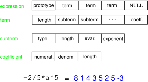
Figure 1 shows a simple example for the internal representation. Using the (non-documented) statement write code; it is possible to have a look at the contents of the compiler buffers in the internal representation. These buffers also contain constructs representing the instructions and additional information needed for pattern matching that we do not discuss here. Only the fact that the terms of an expression are represented by sequences of words of known length is important for the following.
1.3 Preprocessor and Compiler
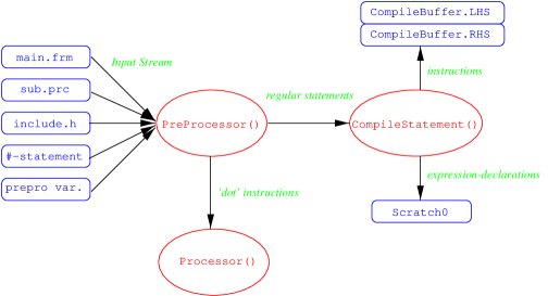
As already mentioned FORM runs a program module by module. The execution of the program is coordinated by the preprocessor. It merges the program text from different sources (files), inserts the preprocessor variables’ values and evaluates the preprocessor instructions (lines beginning with a #). Moreover it passes the statements to the compiler and eventually calls the processor in order to actually execute the modules when it encounters a dot-instruction.
The compiler translates the ASCII-input text line by line into the internal representation described in section 1.2. It writes the definitions of the expressions (the prototypes) into so called scratch-files (with extension .sc0 or .sc1). The instructions are divided into left hand sides (LHS) and right hand sides (RHS) and stored in the corresponding buffers. For an id-statement the LHS corresponds to the (sub-)term that is to be replaced, the RHS corresponds to the expression it is to be replaced with. For other statements the LHS contains other information and in some cases the RHS might not even exist and there is a LHS only. The internal representation also contains all information necessary for pattern matching. The whole procedure is pictured in figure 2.
If the preprocessor encounters a dot-instruction it causes the execution of the instructions stored in the compiler buffers by calling the function Execute, which in turn calls the function Processor. For a given expression the processor decides if it is going to be manipulated in the current module. If this is the case the corresponding terms are read from the scratch-file by the function GetTerm one at a time and passed to the function Generator. This function performs the actual execution of the module for every single input term by generating the output terms according to the instructions stored in the compiler buffers.
1.4 Generating Terms
The generator is the core of FORM. The complex recursive function Generator takes a single term and performes the following operations:
-
•
the term is being checked for sub-terms that have to be inserted.
-
•
the term is transformed to normal form by ordering the sub-terms.
-
•
the instructions of the compiler statement corresponding to the given recursion depth are applied.
-
•
the result is brought to standard form by expanding the sub-terms.
Since the function Generator is called recursively for a given term, all the instructions in the compiler buffers are applied to a single term before the generator proceeds with the next input term. A buffer called workspace is used as a stack for the recursion. The size of the work-space can be increased if necessary by providing a corresponding entry in the set-file. Once all statements have been applied to the first term, the next term in the workspace is taken. The generating procedure yields a tree-like structure for term generation (shown in figure 3), where the execution is not line-oriented (as one might guess naively), but term-oriented.
1.5 Sorting Terms
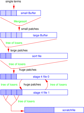
As described in the last section the generator produces a stream of output terms for each input term given. Generally the output terms come unsorted and in redundant form. In order to get a result in standard form, the output terms have to be sorted and equivalent terms (terms equal up to a prefactor) have to be summed up. This is done in a staged procedure using two buffers in the memory (the small buffer sBuffer and the large buffer lBuffer), whose sizes can be adjusted in the set-file and a temporary sort-file on disk. The unsorted terms are written into the small buffer first. If the small buffer gets full, its content gets sorted and is copied to the large buffer, freeing the small buffer for the next patch of output terms. If the large buffer gets full, its content (pre-sorted patches of terms) gets again sorted and is copied to the temporary file, freeing the large buffer. If all terms have been generated for all expressions in a module, the terms that are still residing in the different memory buffers and the sort-file have to be merged together to yield the final expression. This is again been done stage by stage, if necessary by using additional temporary sort-files. The resulting sorted stream of terms is written to the output scratch-file, which is in turn used as the input scratch-file for the next module.
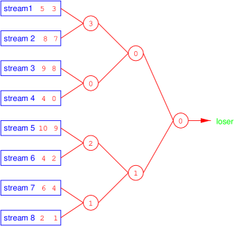
For the sorting of the (unsorted) terms in the first small buffer a modified version of the mergesort-algorithm [2] is used. Like for the well known quicksort-algorithm the number of operations necessary for sorting a problem of size (numbers of terms) grows like . Quicksort is slightly faster, but mergesort provides higher stability against worst cases and the implementation of cancellation of terms can be done more easily. Pre-sorted patches of terms are always merged together by the “tree of losers” algorithm (the idea of the algorithm is shown for integers in figure 4), that is described in [2] for file-to-file sorting. Figure 5 gives an overall view on the staged sorting procedure.
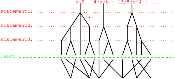
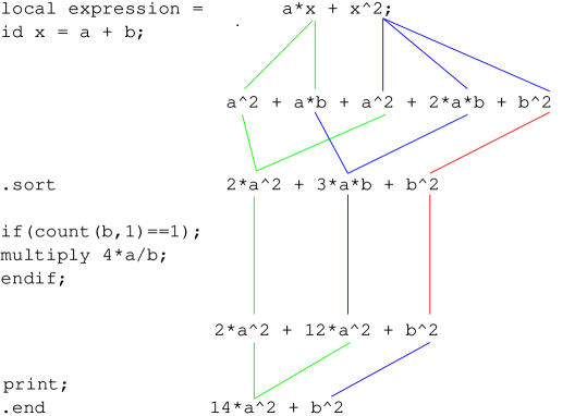
Like the generation of terms the sorting of the output terms yields a tree like structure. Figure 6 shows the generating and sorting trees for the example in the introduction.
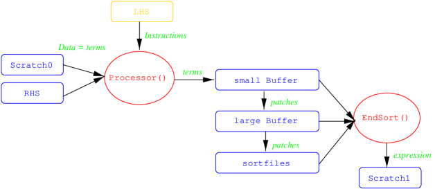
The data flow for the generating and sorting phase of the execution of a module is shown in 7.
1.6 Optimizing and Analyzing the Sequential Code
Before any effort was made to parallelize FORM, the first step was to analyze and optimize the sequential code. FORM was ported to DEC UNIX and the internal used word length was changed from 16 bits (which results in 32-bit arithmetic operations) to 32 bits (64-bit arithmetics), hereby using the full register width of the Alpha-processors. Afterwards this new 64-bit version of FORM was thoroughly tested and the performance was compared to the the old 32-bit FORM. The speedup is almost a factor 2 for small problems; for a large size realistic application (the calculation of a quite complicated 3-loop Feynman diagram) the run-time dropped from 6665 seconds to 4105 seconds by using the larger word size only. Another speedup of about 1.5 was achieved simply by experimenting with different compiler optimization flags.
Another important advantage of the 64-bit version is the use of 64-bit addresses in the management of buffers and files. Using 32-bit pointers the maximum size of files that can be handled is 2GB. In order to deal with larger expressions one has to distribute the data to several files or implement extended position information. This has not been done yet in the 32-bit version of FORM. For the 64-bit version it is not necessary anymore.
The next step before parallelization was profiling FORM in typical applications in order to determine the functions that consume most of the run time. The following is the output of the Digital Unix profiling tool prof when running a yet not very large FORM application program. It shows that the CPU usage is well leveled between functions involved in the generating (marked with a G) and in the sorting of terms (S).
            %time     seconds  cum %   cum sec  procedure

             20.2    501.6201   20.2    501.62 Normalize             G
             13.4    331.3018   33.6    832.92 Compare               S
              8.5    210.6748   42.1   1043.60 PutOut                S
              5.7    141.9512   47.8   1185.55 StoreTerm             S
              3.4     83.7432   51.2   1269.29 TestSub               G
              3.0     73.2539   54.1   1342.54 MergePatches          S
              2.9     72.4668   57.0   1415.01 InsertTerm            G
              0.9     21.7793   87.5   2171.72 EndSort               S
The time needed for compiling the program text into the FORM-internal representation is not dependent on the size of the problem. In realistic applications it is usually negligible.
2. Evaluation of Different Parallel Platforms
During the part of our project that is presented here the following hardware has been used:
-
•
Digital workstation cluster (at TTP Karlsruhe) running DEC UNIX 4.0D
8 nodes with 600MHz Alpha 21164A (ev56) processors and 512MB RAM. -
•
PC cluster (at TTP Karlsruhe) running Linux 2.2.13
4 nodes with 500MHz Intel Pentium III processors and 256MB RAM. -
•
IBM SP2 (at RZ Universität Karlsruhe) running AIX 4.2.1
160 thin P2SC nodes with 120MHz processors and 512MB RAM (256 nodes in total).
For the implementation of the parallel version of FORM the message passing libraries MPI, mostly the MPICH implementation (version 1.1.12) [3], and PVM (version 3.3.11) [4] were used in order to guarantee maximum portability. At the moment PVM is still an important alternative to MPI, but we expect PVM to vanish over the years as several UNIX vendors have already announced to discontinue further development of their PVM libraries. Both message passing systems can make use of specialized device drivers underneath in order to yield maximum communication performance.
2.1 Network Hardware
In the case of the DEC Alpha cluster a variety of network hardware and various implementations of the IP (Internet Protocol) and the device drivers for the message passing libraries exist and have been used:
-
•
DEC DE500-BA Fast Ethernet NIC (100 MBit/s), 12 port 3COM SuperStack 3000 switch,
DEC-UNIX TCP/IP, MPICH/P4. -
•
DEC DEGPA-SA Gigabit Ethernet NIC (1000 MBit/s), no switch (two nodes only),
DEC-UNIX TCP/IP, MPICH/P4. -
•
Myricom Myrinet-SAN NIC 32-bit 33MHz (1.26 GBit/s)[5], dual 8 port Myrinet SAN switch,
DEC-UNIX TCP/Myrinet IP, MPICH/P4, -
•
Myricom Myrinet-SAN NIC 32-bit 33MHz (1.26 GBit/s), dual 8 port Myrinet SAN switch,
ParaStationII[6] software, MPICH/PSM.
Also for the Intel Pentium III cluster two different combinations of network hard– and software have been used:
-
•
3COM 3C905B Fast Ethernet NIC (100 MBit/s), 12 port 3COM SuperStack 3300 switch,
LINUX TCP/IP, MPICH/P4. -
•
Myricom Myrinet-SAN NIC 32-bit 33MHz (1.26 GBit/s)[5], dual 8 port Myrinet SAN switch,
Myricom GM software, MPICH/GM.
For a thorough understanding of the parallel systems’ behavior it is of course crucial to compare their communication performance. For the IP drivers the TCP (Transfer Control Protocol) performance was determined (on workstation clusters the standard low-level device P4 of MPICH uses TCP/IP for the communication over networks). Moreover we measured the bandwidth and latency performance for the MPI(CH) and PVM libraries under different conditions. Here we present the results for the TCP and MPI(CH) measurements only. They are most important for our purposes.
2.2 TCP Performance
The TCP stream (data transfer) performance of the IP drivers for the DEC Fast Ethernet, the DEC Gigabit Ethernet, the Myricom Myrinet and the ParaStationII on the DEC Alpha cluster and for the 3COM Fast Ethernet and the Myricom Myrinet for the Intel Pentium III PC cluster was measured with the standard package netperf [7]. It provides a script that repeats the measurement until a certain level of accuracy is reached. A couple of parameters can be chosen, namely the buffer sizes on both the sending & receiving side and the size of the transmitted packages. The results are shown in figure 8 for optimum buffer sizes for each architecture.
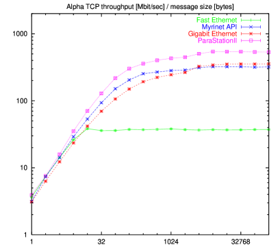
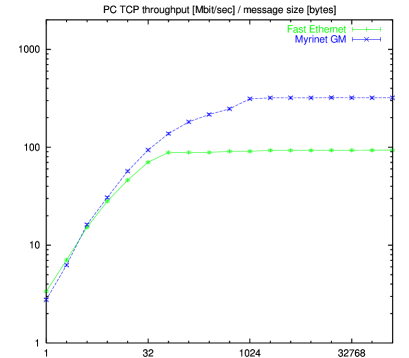
The TCP throughput increases linearly for small message packet sizes. Obviously, in this region the communication is dominated by the protocol overhead. For large messages sizes a maximum throughput value is reached. For the Fast Ethernet on the Alpha cluster (left) this is about 40MBit/s only, whereas the Fast Ethernet on the PC Cluster yields a maximum throughput of more than 90MBit/s, which is about the expected maximum of 100MBit/s. The maximum TCP/IP throughput of the Gigabit Ethernet on the Alpha cluster is 350 MBit/s and for the Myrinet on both clusters a maximum bandwidth of 320Mbit/s is achieved. This is far below the network hardware limit of 1Gbit/s and 1.28Gbit/s resp. The ParaStationII TCP does not use an IP protocol underneath and therefore gives a better maximum performance of 530Mbit/s. The results for ParaStationII and Myrinet GM are shown for completeness only. The corresponding MPI implementations do not use TCP/IP.
2.3 MPI Performance
The performance of the MPI(CH) libraries was examined using the Pallas MPI benchmarks (PMB) [8]. Again a script is provided that can be used to measure the throughput and latency of the messages passing operations without further interaction. Here we present the results for the basic ping-pong-benchmark only. It is the simplest possible single transfer benchmark, based on the blocking MPI routines MPI_send and MPI_recv: one process(or) sends a message of bytes to another process(or), which immediately sends that message back. There is no concurrency with other message passing activity during this test. Thus the bandwidth and latency are measured under optimum conditions.
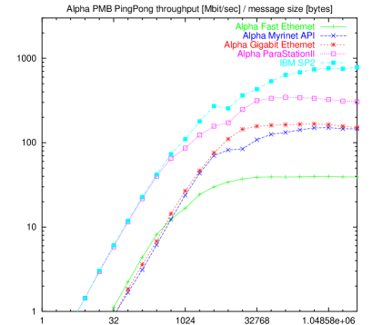
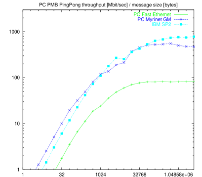
As can be seen from figure 9 the bandwidth increases as the message size does and reaches a maximum value for large message sizes just like the TCP throughput. Obviously the performance of the different IP drivers directly translates to the MPI(CH) performance. On both clusters adding the MPICH layer causes no dramatic effect for the Fast Ethernet, but the bandwidth for the Myrinet and the Gigabit Ethernet drops below 200Mbit/s. The implementations of MPI that do not use TCP/IP show better performance: the maximum bandwidth of MPICH/PSM on the Alpha cluster is 350Mbit/s and of MPICH/GM on the PC cluster even 550MBit/s. The MPI implementation on the IBM SP2 reaches a maximum bandwidth of 800 MBit/s.
In figure 10 the measured MPI(CH) latency for the ping-pong benchmark is shown. The latency ranges from a few microseconds for small messages sizes up to a second for large message sizes. Using MPI(CH) over the IP protocol results in a minimum latency of more than 200 microseconds. Lower latencies can be achieved with special device drivers only. It turns out that the minimum latency for MPICH/PSM on the Alpha cluster (about 40 microseconds) is about the minimal latency on the IBM SP2, but the minimum latency on the PC cluster using MPICH/GM is even smaller: about 20 microseconds.
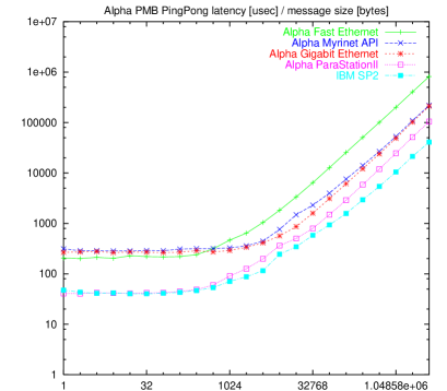
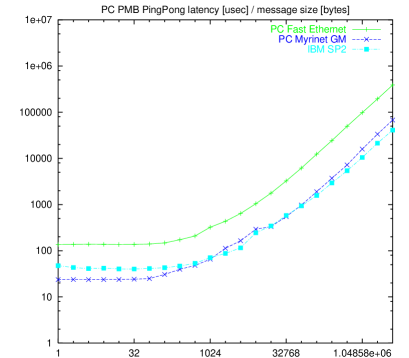
It is important to note that the latency does not increase dramatically up to 1024 bytes. In practical programming that means that whenever a small amount of data (much less than 1024 bytes) is sent one can use the corresponding message to transmit additional information (e.g. statistics) without increasing the latency.
3. The Parallel Version of FORM
3.1 The Parallelization Concept for FORM
As has been already mentioned, FORM is specialized in working with very large expressions, typical jobs run for weeks and can need Gigabytes of temporary disk space. So the idea of parallelizing FORM is obvious and interesting not only because distributing the CPU usage would speed the program up but also because a distribution of the large temporary data could make even larger problems accessible.
For running typical multi-loop calculations, where several hundred or thousands of single diagrams have to be calculated, a “trivial” parallelization by distributing the diagrams to different computers (e.g. with a distributed make-command) is an obvious solution. Still there is a strong interest in speeding up the calculation of complicated single diagrams in both the programming and debugging phase of a project and production jobs.
The limitation of performing almost only local operations makes FORM very well suited for parallelization and the concept of parallelization is straightforward: distribute the input terms among the available processors, let each of them perform the local operations on its input terms and generate and sort the arising output terms. At the end of a module the sorted streams of terms from all processors have to be merged to one final output stream again. The compiling of the program-text to the internal representation was considered to not be worth parallelizing. This concept indicates to use a master-slave structure for the parallelization, where the master would store the expressions and distribute and recollect all the terms of each expression.
For the implementation of this raw concept we used a four step strategy:
-
•
one process(or) generates terms, a second process(or) sorts the output terms
-
•
instead of only one process arbitrary many processes perform the sorting.
-
•
the input terms are distributed and the term generation is also done in parallel
-
•
full FORM functionality, avoid or handle worst cases, load-leveling, fault tolerance
This approach has several advantages, the most important being that having working versions in every stage gives us a good idea of how good the parallelization is and the possibility of realistic tests even at a very early stage.
3.2 The Two-Processor Version
This first step of the parallelization turned out to be very useful, since it not only gave a deep insight of how changes to the source code of FORM have to be made without affecting the efficiency of the well optimized sequential code. It also served as a check of whether and how the concept could or could not lead to a decent speedup. It could be shown that for parallelizing software on a cluster of very fast workstations the importance of avoiding communication overhead can not be overstated, especially concerning the latency of network-communications. It was clear after these experiments that all the communication had to be done in a buffered way, since sending around single terms increased the run times of the two-processor code up to a factor 20. With the buffered version the run-time could be limited to about 1.5 times of that of the sequential code with two workstation connected by a 10 Mbit/s Ethernet using the PVM and MPI(CH) libraries. This was considered to be fast enough since in this case due to only minimal work-load overlap we merely were adding the communication overhead.
3.3 Parallel Sorting
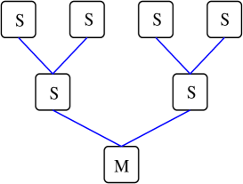
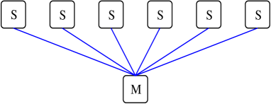
The second step was to distribute the output terms among arbitrary many processors and do the sorting in parallel. Since this part of the sorting relies strongly on communication between the processors, it most probably sets the limits of parallel speedup. A first try was to map the “tree of losers” used in FORM to merge sorted patches onto the processors as shown in figure 11 (left). While it would distribute the workload in an optimal way this approach adds too much communication overhead.
This is why in the end a much simpler communication structure was used (see figure 11, right), where all the slaves send their sorted terms to the master process and this process uses a local “tree of losers” to merge the output streams of the slave-processes. Additional effort was made to overlap the work on the master process with the sorting done on the slaves, which caused a much deeper interference with the sequential code.
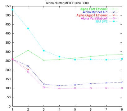
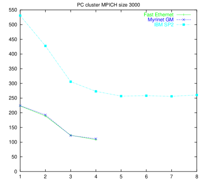
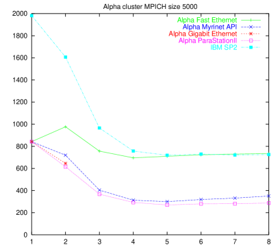
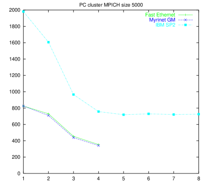
Since only the sorting is of interest any problem that produces a sufficient number of intermediate terms could have been used to test the parallel speedup. We chose a very simple program, that expands the expression and then replaces by which results in a short, easy to check result and—by choosing different values of —can be scaled in an easy way. The run-times we measured with this version and different combinations of communication hard-/software are shown in figure 12 for two different values of : (top) and (bottom). The corresponding problem sizes are MB and MB resp. for the 64-bit architecture of the Alphas and roughly half as large for the 32-bit systems. We find that the performance of the Fast Ethernet on the Alpha cluster is so low that no speedup can be achieved. All other systems yield a maximum speedup of about a factor of 2.5 that is apparently independent of the problem size. Obviously the generating processor is able to keep about 4 processors busy in sorting only, i.e. there is a rather quick saturation in the speedup. As a result the runtimes of the parallel sorting version of FORM on the IBM SP2 hardly reach the runtimes of the sequential version on the Alpha and the PC clusters. On the other hand the speedup is not demolished again by the use of too many processors, a fact that has been explicitly checked with 32 processors on the IBM SP2.
3.3 Parallel Generating
![[Uncaptioned image]](/html/hep-ph/0007221/assets/x20.png)
![[Uncaptioned image]](/html/hep-ph/0007221/assets/x21.png)
![[Uncaptioned image]](/html/hep-ph/0007221/assets/x22.png)
Figure 13: Results for the parallel generating version running a test program that amounts to ideal input for the parallel version. Shown are the run-times[sec]/number of processors for the different architectures: the Alpha cluster (upper left), the PC cluster (upper right) and the IBM SP2 (left).
The last step towards a working prototype is the distribution of input terms among all processes before generation of the output terms. The slave-processes of course also need all the information necessary for the generation of the terms, which is at the moment realized by having them all read the program text file and compile their own internal representation and broadcasting only the rest of necessary information from the master process.
Just as with the sorting the speedup is strongly dependent on the number of terms sent within one message. In the current implementation this number can be changed at the start of the program, but it might be a good idea to adjust this number module-wise. Of course choosing a too coarse grained distribution will result in the danger of running into worst cases, where all the work sits in only one of the input patches, and only one processor is busy. On the other hand, the fine grain distribution causes more overhead. The best setting turned out to be not only dependent on the underlying soft/hardware, but also strongly dependent on the problem that is run. The distribution is organized such that the master sends a patch of terms to each slave process at the beginning of the module and then waits for the slaves to ask for new terms whenever they are finished with their last patch of input terms. This actually turns the concept in that of a client-server situation which will also be useful to make the slaves receive any kind of global information when the need arises. It also produces a decent load leveling among the slaves, which can be controlled by the size of the input-patches and could even be adjusted during run-time for further improvement.
Figure 13 shows the results for a test program that amounts to ideal input for the parallel generating version. It starts out with a bit more than 2000 terms. On each of these terms a lot of work is done and a huge number of intermediate terms is produced. In the end the result collapses to a rather small expression.
It is obvious that due to the client-server-like parallelization strategy one processor (the server-node) is kept busy with the organization of the parallel data flow and a second processor alone does hardly yield a speedup. With this exception the speedup is found to be almost linear for all architectures. In contrast to the parallel sorting version the fully parallelized version of FORM gives such a high speedup on the IBM SP2 that it becomes competitive to the Alpha and the PC cluster. As expected for this particular test program the dependence on the number of input terms distributed at once is not strong, because the work is uniformly distributed among the terms. Obviously the distribution of a thousand terms at once is too coarse grained and results in a more or less straight line in the speedup plots for a number of processors (i.e. more than 2 slave processes).
3.4 Special Solutions to Non-Local Operations
There are a few non-local operations that are particularly useful. In order to at least partially parallelize these operations special solutions had to be found:
-
•
preprocessor instruction #redefine
The preprocessor instruction #redefine allows to change a preprocessor variable depending on the occurrence of certain terms. At first glance this seems to cause problems for the parallel version, when different slave processes assign different values to the same preprocessor variable. In fact it is sufficient to let the master know the last (w.r.t. the input terms) modified value of the preprocessor variable. This already guarantees that the parallel version uses the same value for the preprocessor variable in the next module that the sequential version would have used.
-
•
module option polyfun
The polyfun module option is used to add up the arguments of certain functions (such as coefficients). In some applications this reduces the number of terms drastically. In the parallel version only the “tree of losers” on the master-process had to be modified. The slaves use the usual sort routines that already give the correct behavior.
-
•
collect statement
The collect statement collects bracketed expressions in function arguments. In the parallel version this can completely be done by the master-process.
-
•
keep brackets statement
The keep brackets statement hides the contents of brackets from execution of the statements of a module. The parallelization of this feature is not straightforward and only partially implemented in the current version. But corresponding tests show that this version is sufficient for real applications.
3.5 A Real Application: Moments of Structure Functions
With the additions discussed in the last section it was eventually possible to run the wide-spread FORM-package MINCER [9], which can calculate certain types of Feynman diagrams up to the three loop level. First some easy standard integrals were calculated in parallel and proven to come out correctly. After that the computation of diagrams of a still ongoing project, the calculation of higher moments of structure functions [10] was chosen as a real application to test the parallel version of FORM.
When running MINCER usually over a hundred modules are executed (depending on the diagram under consideration). In most of those only very few terms are active, which amounts to ‘worst cases’ for the parallelization. Also the results are received from the FORM-code written for the sequential version of FORM without any modification or optimization. This corresponds to a perfect code reuse. Figure 14 shows the results for a typical diagram. Obviously the speedup is not linear any more, but reasonable: a factor of 2.5 with 4 nodes on the PC cluster using MPICH/GM, a factor of 4.5 with 8 nodes on the Alpha cluster using MPICH/PSM and a factor of 6 with 12 nodes on the SP2. For the problem under consideration obviously distributing single terms () or too large patches of terms () is not a good idea and a value in the range of yields best performance.
![[Uncaptioned image]](/html/hep-ph/0007221/assets/x23.png)
![[Uncaptioned image]](/html/hep-ph/0007221/assets/x24.png)
![[Uncaptioned image]](/html/hep-ph/0007221/assets/x25.png)
Figure 14: Results for the fully parallelized version running MINCER on a typical 3-loop diagram of an actual calculation. Shown are the run-times[sec]/number of processors for the different architectures: the Alpha cluster (upper left), the PC cluster (upper right) and the IBM SP2 (left).
4. Conclusion & Outlook
We have shown that at least for a symbolic manipulation program like FORM, which with a few exceptions allows local operations only, a successful parallelization can be done even on workstation clusters using message passing libraries. Of course the speedup that can be achieved depends strongly on the problem under consideration. Ideal input to the parallel version and a problem size that is not too small yields a speedup that is linear in the number of slave processors. For realistic complex applications the speedup is still considerable. It is particularly noteworthy that these results have been achieved with FORM programs that were written for the sequential version and have not been modified. Generally the FORM user does not have to know anything about the mechanism behind the parallel version to run already existing programs in parallel. Still, some knowledge can help to tune them and achieve a higher speedup.
The performance and stability of the high performance Myrinet hardware and the corresponding ParaStationII and GM drivers are sufficient for development purposes. Still we would not yet recommend to use them in production systems that demand uptimes of several months. Note that the parallel version of FORM using the message passing is actually independent of the type of network hardware and a particular implementation of MPI or PVM. Therefore it can be used on any parallel system that provides one of these message passing libraries.
Since the parallel program is actually based on FORM version 3.0, which is in preparation and offers some new and powerful features, we will investigate whether and how these new features can be implemented in the parallel version. We are also interested in porting the parallel version of FORM to SMP (symmetric multi-processing) architectures, where directly IPC (inter-process communication) or threads can be used to minimize communication overhead. The main aim of all these efforts is to get from the current stage of a stable prototype to an easy to use, powerful and reliable program that is not an end in itself, but a useful tool in real life applications on a wide spectrum of (parallel) architectures.
Acknowledgements
This paper was supported by the DFG-Graduiertenkolleg ”Elementarteilchenphysik an Beschleunigern” and the DFG-Forschergruppe ”Quantenfeldtheorie, Computer-Algebra und Monte-Carlo-Simulation” under contract number FOR 264/2-1.
References
- [1] J.A.M. Vermaseren, Symbolic Manipulation with FORM, published by CAN (Computer Algebra Nederland), Kruislaan 413, 1098 SJ Amsterdam, 1991, ISBN 90-74116-01-9.
- [2] D. Knuth, The Art of Computer Programming, Addison-Wesley, 1997.
- [3] MPI(CH) homepage: http://www.mcs.anl.gov/mpi/
- [4] PVM homepage: http://www.epm.ornl.gov/pvm/
- [5] Myricom homepage: http://www.myri.com
- [6] ParaStationII homepage: http://wwwipd.ira.uka.de/ParaStation/PSM/
- [7] Netperf homepage: http://www.netperf.org/nerperf/NetperfPage.html
- [8] Pallas MPI Benchmarks: http://www.pallas.de/PMB2/
- [9] S.A. Larin, F.V. Tkachov, J.A.M. Vermaseren, Preprint NIKHEF-H/91-18 (1991).
- [10] S.A. Larin,T. van Ritbergen, J.A.M. Vermaseren Nucl. Phys. B427 (1994) 41, S.A. Larin, P. Nogueira, T. van Ritbergen, J.A.M. Vermaseren, Nucl. Phys. B492 (1997) 338, A. Rétey, J.A.M. Vermaseren, Preprint TTP00-13 (2000).