DESY 05-155, RCNP-Th05028
Optimization of Lattice QCD codes for the AMD Opteron processor
Abstract
We report our experience of the optimization of the lattice QCD codes for the new Opteron cluster at DESY Hamburg, including benchmarks. Details of the optimization using SSE/SSE2 instructions and the effective use of prefetch instructions are discussed.
1 Introduction
Lattice QCD is a powerful method to study Quantum chromodynamics (QCD) in a nonperturbative way. In lattice QCD, a path integral is directly evaluated on a discrete space-time lattice by means of the Monte Carlo method. As computer technology advances PC clusters can also be used for lattice QCD simulations as well as a number of commercial supercomputers.
Since lattice QCD simulations demand huge computer power, it is very important to optimize the simulation codes so as to exploit the full potential of the processor. Thus we optimize the hot spots of the codes such as the operation of a Dirac operator to a spinor (referred as hereafter) and linear algebra of spinors, e.g.
-
•
: scalar product of two spinors
-
•
: norm square of a spinor
-
•
: add two spinors with a constant factor and assign the result to one of the source spinors
In the simulation, a spinor is defined as a vector with 12 complex components on each grid point (site) of the lattice, and a gauge field is defined as a complex matrix on a link, which connects nearest neighbor sites. Numerically the operation is a combination of a complex matrix times a complex vector. From a technical point of view, we should optimize these two applications separately since is processor limited as it needs more than one thousand floating point operations per site, while the linear algebra routines demand more data transfer than actual computations (memory limited).
In this note we report our experience of the optimization of the lattice QCD codes for the new PC cluster with the AMD Opteron processor [1] which is recently installed at DESY Hamburg. Of course the parallel computing with multiple processors is of our interest, however, we have optimized here only single processor version as a first step. We also compare benchmarks with an older PC cluster with the Intel Xeon processors (See Table 1 for the specification of these two processors).
| AMD Opteron | Intel Xeon | |
| Processor speed | 2.4 GHz | 1.7 GHz |
| L1 Data Cache | 64 kbytes | — |
| L2 Data Cache | 1024 kbytes | 512 kbytes |
| # of SSE registers | 16 | 8 |
| Cache line size | 64 bytes | 128 bytes |
2 SSE instructions
To achieve the full performance, it is important to make use of the special feature of the processor. Streaming SIMD extensions instruction sets (SSE) is the case for us [2]. SSE is designed to process 128-bit long data which may contain multiple elements of vectors and is suitable for vector operations like and linear algebra. Both Opteron and Xeon processors support SSE and SSE2 (the first extension of SSE) and have special 128-bit long registers for the SSE instructions (SSE registers) as summarized in Table 1. Note that neither of them supports SSE3, the latest extension of SSE.
In our group, simulation codes written in the standard C language with SSE/SSE2 have already been developed for the Xeon processor. These SSE instructions are embedded to the C codes by defining macros using GCC inline assembly [3]. The macro contains the SSE instructions that load data from system memory to a SSE register, operate on vectors on the SSE registers, store data to system memory, etc.
Technically it is also important to consider the latency of the SSE instruction itself as well as the latency caused by the data transfer. Usually an instruction needs several processor cycles to finish the operation. Although the Opteron processor can execute up to three instructions per cycle, the processor has to wait until the previous operation is finished if these two operations are interdependent. One can avoid this by performing independent operations by using several SSE registers. For instance, in a macro with SSE instructions, we first load -bit data to four SSE registers per function call. Then the operation on the first SSE register starts while data loading proceeds on the third and the fourth registers. In the same way, the data on the first SSE register can be stored to the system memory while the calculation on the third and the fourth registers are going on. This is how one can hide the latency of the SSE instructions. In addition to this, of course, the reduction of the number of instructions and/or the use of lower latency instruction improves performance. Opteron’s twice the legacy number of registers (see Table 1) can eliminate substantial memory access overhead by keeping intermediate results on SSE registers and can hide latency of each instruction more effectively.
3 Prefetch instruction
The mismatch between the memory bandwidth and the processor throughput is one of the big origins of latency. Typical difference of them is a factor of ten. The prefetch instructions, which read data from system memory into the level 1 (L1) data cache, take advantage of the high bus bandwidth of the Opteron processor to hide latencies when fetching the data from the system memory. Data transfer is processed in background and eight prefetch instructions can be “in flight” at a time. As a prefetch instruction initiates a read request of a specified address and reads one entire cache line that contains the requested address, prefetch instructions can improve performance in situations where the sequential addresses are read. This is the case for lattice QCD simulations. Once the data is in the L1 cache, there is almost no latency as 128-bit data can be loaded into a SSE register within two processor cycles. Note that the number of prefetch instructions is dependent on the length of one cache line, which is 64 bytes for the Opteron processor, while 128 bytes for the Xeon processor.
One of the important parameter for the effective use of prefetch instructions is “prefetch distance,” which denotes how far ahead the prefetch request is made. In principle, the prefetch distance should be long enough so that the data is in the cache by the time it is needed by the processor. The actual distance is dependent on the application.
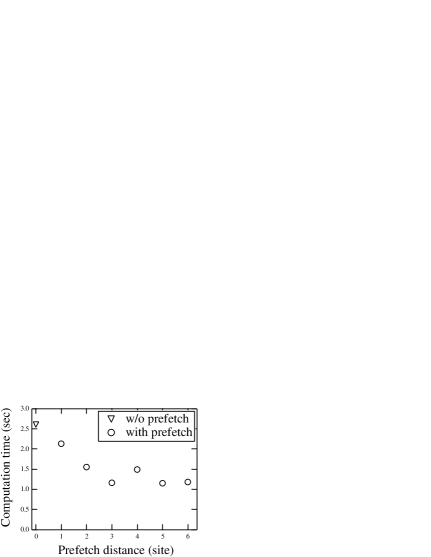
We show the prefetch distance dependence of the performance of the macro which computes a complex matrix times a complex vector on each site in Fig. 1. This operation can be regarded as a prototype of . We find that the macro with the prefetch distance three is more than twice faster than that without prefetch instruction. It is also interesting to note that shorter prefetch distance than the optimal distance (distances 1 or 2 in Fig 1) gives worse performance compare to longer prefetch distance such as distance 5 or 6. This result suggests that the prefetch distance should not be chosen too small.
Another important parameter is the amount of data to be processed for each “prefetch-computation” iteration. In general, for an optimal use of the prefetch instruction, the data stride per iteration should be longer than the length of a cache line. Although it is easier to hide latency in the SSE macro with more data per iteration, too big data stride like the length of more than four cache lines per iteration may reduce performance. This is also dependent on the number of source fields in the application, since the number of multiple prefetch requests is limited. This number is eight for the Opteron processor.
We perform several tests for each application and determine the prefetch distance and data stride one by one. For instance, in the routine to compute , data stride is the length of two cache lines and prefetch both source fields at six cache lines ahead. In the routine, the data stride is the length of a cache line and the prefetch distance is five cache lines.

4 Benchmarks
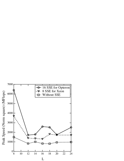
To see the effectiveness of the implementation of SSE instructions and of optimization, we show benchmarks of the linear algebra routines with and without SSE instructions in Figs. 2, 3 and 4. We also plot the result of the original code using 8 SSE resisters, which is written for the Xeon processor and compatible with the Opteron processor.
The use of SSE instructions improves the performance even before the optimization for the Opteron processor. Besides we have another considerable gain by tuning prefetch distance and by making use of 16 SSE registers.
The lattice size dependence of the performance is rather large for linear algebra routines. Good performance (6.4 GFlops) of calculation at in Fig. 2 is due to the cache effect, where a spinor field (72 bytes Mbytes) can entirely fit into the L2 cache. We also observed slowing down in calculation at as shown in Fig. 3 and in calculation at as shown in Fig. 4. They are caused by bank conflict in multiple prefetch requests. It happens for certain lattice volumes when two source fields are loaded as . However, this slowing down can be cured by extending the prefetch distance of the second source by four, which is obtained by the maximal number of prefetch request divided by the number of source field, . Such treatment is based on the observation in Fig. 1 that the longer prefetch distance does not affect performance. The final version is roughly twice faster than the original C codes without SSE instructions.
In Table 2, we compare the throughput of the Opteron processor to that of the Intel Xeon processor. For the Dirac operator , the ratio of the throughput is almost the same as that of the processor clock speed (2.4 GHz/1.7 GHz =1.41) except for the 32-bit version at , where the ratio is 1.64 1.41. This can again be the cache effect since a spinor and a gauge field can entirely fit into the L2 cache ((72+96) bytes Mbytes).

| Opteron | Xeon | ratio | |
|---|---|---|---|
| (32-bit, L=8) | 2462 | 1503 | 1.64 |
| (32-bit, L=12) | 2037 | 1421 | 1.43 |
| (64-bit, L=8) | 1140 | 799 | 1.43 |
| (64-bit, L=12) | 1131 | 796 | 1.42 |
| (32-bit, L=16) | 1370 | 617 | 2.22 |
| (64-bit, L=12) | 1090 | 554 | 1.97 |
| (64-bit, L=16) | 661 | 353 | 1.87 |
For linear algebra we have more gain as expected from the difference of the processor clock speed. The larger data cache and the improvement of memory bandwidth may reflect the result since linear algebra routines are rather memory limited.
5 Summary
In this report, we discuss the details of the optimization of the lattice QCD codes for the AMD Opteron processor.
Tuning of prefetch distance for each application can improve performance by more than a factor of two. The prefetch instruction, however, may cause significant slowing down in some linear algebra routines at certain lattice sizes due to bank conflict. We found that this slowing down can be cured by adopting two different prefetch distances for each source field. The effect of the modification in SSE instructions can be observed only after the adjustment of the prefetch instructions.
Large cache effect is observed not only for the linear algebra routines but also for the routines when the source fields can fit into relatively large L2 data cache of the Opteron processor. This suggests that the PC cluster of the Opteron processor can achieve high performance when the sublattice size becomes small enough. As a next step of this work, we will develop a parallel version of the codes.
6 Acknowledgement
The author would like to thank H. Wittig and Y. Koma for a number of useful discussions. The author appreciate the original codes and the benchmark programs written by L. Giusti, M. Lüscher and H. Wittig, which is the basis of the improvement reported here.
The author would also like to thank U. Ensslin of DESY IT group for technical supports.
References
- [1] Software Optimization Guide for AMD Athlon 64 and AMD Opteron Processors (Publication #:25112, Issue date November 2004)
- [2] AMD64 Architecture Programmer’s Manual Vol. 1, Chap. 4 (Publication #:24592 Issue date September 2003)
-
[3]
Sandeep.S,
GCC-Inline-Assembly-HOWTO
(http://www.ibiblio.org/gferg/ldp/
GCC-Inline-Assembly-HOWTO.html)
v0.1, 01 March 2003.