![[Uncaptioned image]](/html/hep-ex/9909054/assets/x1.png)
SCIPP 99/38
September 1999
TRACKING AND VERTEXING AT A HIGH ENERGY LINEAR COLLIDER
Abstract
The relative merits and disadvantages of various alternatives for vertexing and central tracking detectors for the Linear Collider detector are presented. Research and development prospects for the various alternatives are also discussed, as well as a preliminary study of the prospects for forward () tracking.
Talk presented at “LCW99”, the International Workshop on
Linear Colliders
Sitges, Barcelona, Spain, April 28–May 5, 1999
1 Introduction
Over the last few decades, the design and construction of tracking systems for cylindrical geometry colliding beam detectors has become a very advanced and refined field. Nevertheless, the proposal to build a High Energy Linear Collider (LC), with a center-of-mass energy as high as TeV, and the physics that would motivate such a facility, combine to present a number of challenges and opportunities for the design of the associated charged particle tracking system. This report will summarize and provide perspectives on recent R&D accomplishments and suggestions for future R&D, presented at the 1999 International Workshop on Linear Colliders, which are geared towards meeting these challenges and exploiting the unique opportunities provided by the Linear Collider environment.
2 Motivation for Precise Track Reconstruction
The physics which motivates the Linear Collider demands an excellent tracking system. The desire to perform reliable final-state flavor tagging places a strong demand on the precise measurement of the track origin parameters. For example, the branching fraction, which is about for the Standard Model Higgs boson for GeV/c2, and less for larger , is an important signal for distinguishing between the Standard Model Higgs and that of extensions or alternatives to the Standard Model. While inclusive charm tagging has been done at the pole at LEP and the SLC, current tracking systems would not be able to fully exploit the information available at a Linear Collider, and thus improvement is desirable. As another example, in order to fully exploit the natural width in the measurement of Higgs properties in the reaction ; , an asymptotic () momentum resolution of is required.
3 Linear Collider Backgrounds
A substantial amount of thinking about LC tracking systems has been driven by potential machine backgrounds. In the intense field associated with the collision point, beamstrahlung photons convert to form pairs. Since the scale of this process is that of the electron mass, these pairs can be curled up with a strong solenoidal magnetic field – a design criterion that is compatible with precise momentum reconstruction. Although studies continue, it is now thought that a field of 3-4 T is sufficient to admit the use of a 1 cm beampipe, which is advantageous for precise vertexing.
Somewhat more difficult to model, the tracking system is expected to be bathed in photons from unconverted beamstrahlung radiation that scatters off of the apertures of the machine lattice and masking elements. This background component did much to limit both the instantaneous and integrated luminosity of the SLC by producing uncomfortably high occupancy in the SLD drift chamber as the beam divergence angle was increased to reduce the spot size, or whenever the orbit of the beams in the machine went slightly out of tolerance. A tracking system with the highest granularity in both and will be most immune to this background.
As for its hadronic counterparts, minimum bias (‘minijet’) events begin to become an issue at the LC. Current estimates [1] are that a 500 GeV LC event will have a few-percent probability of being coincident with a minijet event. For both the TESLA design, with bunch crossings per train separated by 337 nsec each, and the JLC/NLC design, with crossings per train separated by 2.8 nsec, it would be desirable to have timing which would permit the rejection of tracks (or hits from the photon background) which emanate from the wrong bunch. Thus, ‘temporal segmentation’ is also important, and particularly challenging in the case of the JLC/NLC.
Finally, neutron halo from the beam dump and collimators, with an estimated fluence of for the inner detectors in the JLC/NLC design, raises some concerns about radiation damage.


4 Outline and Discussion of Proposed Tracking Alternatives
An optimal tracking system has as large a radial extent as possible: both inward, in order to optimize the measurement of the track origin parameters (impact parameter), and outward, in order to provide as large a lever arm as possible for the momentum measurement. A large magnetic field is desirable, in order to provide maximum curvature for the momentum measurement. Minimizing the single hit resolution, both in absolute terms as well as normalized to radiation length, improves the precision of the track reconstruction and limits the effects of multiple scattering. It is interesting to note that the central tracker plays an important role in the measurement of all five tracking parameters. For example, Figure 1 shows the impact parameter resolution obtained [2] with and without the central tracker in the North American ‘S’ design (to be described below). It can be seen that the angular measurement, and particularly the curvature measurement, provided by the central tracker are important for constraining the track origin parameters.
While the European and Asian studies have focussed on a large volume gaseous central tracker (TPC and drift chamber, respectively), the North American community is considering two options, shown schematically in Figure 2: a large (‘L’) option with a TPC, and a compact (‘S’) option with a central tracker composed of three doublets of silicon drift or silicon strip detectors. All alternatives include a multi-layer silicon pixel inner tracker for precise vertexing, with innermost layer at cm ( cm) for the ‘L’ (‘S’) alternative; ongoing studies indicate that it may well be possible to reduce the ‘L’ detector inner radius somewhat. The three gaseous tracking alternatives are immersed in an axial field of 2-3 T, while the ‘S’ alternative assumes a 6 T field. The ‘S’ alternative includes a silicon strip forward tracking system; similar systems are currently under study for the other three alternatives. Intermediate tracking layers are under consideration as well for the four alternatives.
4.1 Tracking Performance

Figure 3 compares the momentum resolution of the North American ‘L’ detector, fairly typical of the three gaseous tracking alternatives, with that of the ‘S’ detector. At high momentum, the large magnetic field and excellent (10 m) space-point accuracy of the ‘S’ detector compensates the longer lever arm of the ‘L’ detector, leading to a roughly equivalent momentum resolution. At low momentum, the relatively low information content per radiation length of solid state tracking (1% per layer is assumed) leads to momentum resolution worse for the ‘S’ detector. Ideas relating to how this difference may be lessened are sketched below; an important question to answer via simulation studies is that of whether or not this difference in momentum resolution has any impact on the physics to be studied. Figure 3 also shows the impact parameter resolution. The superior performance of the ‘S’ detector is primarily due to the proximity of the first measurement layer to the interaction point.
5 Vertexing Options
The intense pair background leads to an occupancy at small radius as high as 1 hit/mm2/bunch-crossing, leading to the necessity of a pixel system for the innermost detector, for which the fine granularity can permit the occupancy to be low enough to do physics. One very attractive possibility is CCD detectors. Current CCD vertex detectors, such the SLD VXDIII detector [3], feature a small (m m) pixel dimension, achieve better than m resolution in both and , and are thin (0.4% per layer). On the other hand, though, the need to shift the ionization signal by row and then column to the single readout pad makes the CCD readout slow, and the CCD itself susceptible to radiation damage. Active pixels, for which the readout is bump bonded to the individual pixel sensors, are both fast and radiation-hard, but are relatively thick, and do not achieve as small a pixel dimension as do CCD’s. Time remains, however, to address the shortcomings of these two approaches; the status of ongoing pixel detector R&D is presented below.
5.1 CCD Detector Research and Development
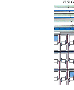
The two critical challenges to be met if CCD’s are to be used for inner tracking layers at the LC are the readout speed and the radiation sensitivity. The SLD VXDIII has a readout bandwidth of 25 MHz, which allows for the complete pixel-by-pixel readout of the cm CCD ladder in approximately 200 msec. In the TESLA setting, with the detector running in the proposed untriggered mode so that the beam crossing can not be inhibited during readout, this leads to an integration over all bunch crossings in a single train, and thus an unacceptably high occupancy. The LCFI collaboration in the UK [6] is currently exploring the possibility a column parallel, rather than pixel-by-pixel, readout system (see Fig. 4). This parallel readout, combined with a proposed readout bandwidth of 50 MHz, would allow for the readout of the LC CCD ladders in 25 sec, integrating over only individual pulse crossings.
A group at the University of Oregon in the US has been studying the mechanisms of radiation damage in hopes of devising a solution suitable for the expected LC neutron fluence of approximately /cm2/yr in the inner layers of the tracking system. Traps created by lattice deformations caused by neutron scattering begin to reduce the efficiency of the pixel-to-pixel charge transfer after approximately neutrons/cm2. The approach of the Oregon group has been to fill these traps via a broad illumination of the pixel array just prior to the arrival of the signal. The diffusion of the electrons which thus fill the traps is slowed by holding the array at cryogenic temperature (190 K in the Oregon study). The Oregon group has found that the neutron tolerance can be increased in this way to greater than neutrons/cm2, with some reason to believe that the limit may be substantially higher. In a LC CCD pixel tracker, this solution would be implemented by clocking a single row of artificially introduced charge through the pixel arrays just prior to the arrival of beam at the interaction point.
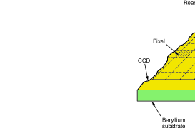
In addition, the LCFI collaboration intends to study the feasibility of further thinning the CCD substrate while thickening the epitaxial (sensitive) layer. By making the ladder thinner, it is hoped that the current material burden of 0.4% per layer can be reduced to as little as 0.12% per layer. Thickening the epitaxial layer would improve the overall S/N of the CCD array, allowing for the possibility, with appropriately optimized readout electronics, of single-hit resolution of 3.5 m or better.
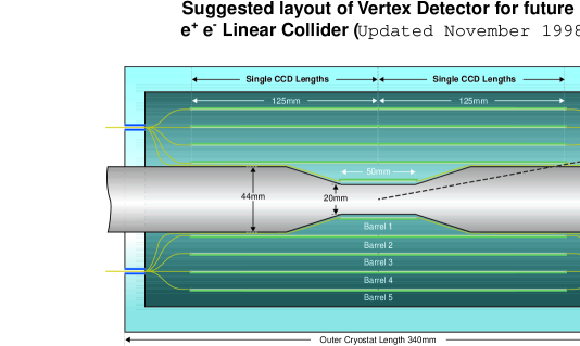
A possible layout of a CCD inner tracking detector is shown in Fig. 5, for the case of a 1 cm beampipe. This layout provides 5-hit coverage to , and at least two hits out to . The resolution of this device, for , has already been exhibited in Fig. 3. For the calculation represented by this figure, a single-hit resolution of 5 m was assumed, as well as a material burden of 0.12% per layer.
5.2 Active Pixel Sensor Research and Development

Active Pixel Sensor (APS) arrays, with individual readout electronics bonded to each pixel site, avoid the need to transfer charge pixel-by-pixel to a common readout pad, and thus avoid the problems of radiation hardness and readout speed encountered by CCD arrays. The development of large-scale hybrid arrays, for which the pixel sensor and the electronic readout are on separate chips which are connected together by a multitude of precision bonds, is fairly advanced, and is part of the baseline design of LHC detectors. However, existing APS implementations suffer from two disadvantages which detract from their desirability for a LC detector – the pixel dimension and the material burden. The scale of the diffusion plume for the electron signal in 300 m of Si is m. Thus, the pixel dimension must be of this order or less to exploit charge sharing in order to achieve a single-hit resolution of 10 m or better. On the other hand, the footprint of readout and driving circuitry for the individual pixel channels has not yet been reduced to this scale. In addition, the hybrid approach, while proven, requires separate detector and readout planes, as well as a high density of metallic bonds and readout and cooling infrastructure. For example, the ATLAS APS detector [4] has a pixel pitch of m, and a material burden of per layer. With continued R&D however, it has been suggested that single-hit resolution as good as m, with a material burden of as little as per layer, may be achieved for an APS system. [5] A comparison of the impact parameter resolution between the proposed CCD system and an APS system based on these projections is shown in Fig. 6.
APS R&D efforts are divided into two approaches, which are being explored by a collaboration of groups from Milano, Cracow, Warsaw, Helsinki, and Strasbourg, as well as a Hawaii-Stanford group in the US: efforts to improve upon existing hybrid implementations, and exploration of possible monolithic approaches. The most promising hybrid approach, shown in Fig. 7, involves interleaving pixels of dimension m m, but with a readout pitch of roughly 200 m. Capacitive and resistive charge division would be used to exploit the charge sharing between the uninstrumented pixels. Prior studies with strip, rather that pixel, detectors with a 200 m readout pitch [7] indicate substantial resolution gain as the number of interleaved strips is increased, with the single-hit resolution improving from 77 m with 0 interleaved strips to 9.7 m with 3 interleaved strips. The European collaboration has received a set of 10 wafers of interleaved pixel detectors, and has performed basic I-V tests. They see no obvious flaws in the concept and layout, and are in the process of designing a commensurate readout chip to allow rigorous tests of the performance.
Monolithic APS detectors are intrinsically thinner devices, in that they do not require a separate readout plane. In addition, not requiring channel-by-channel bump bonding, they are mechanically simpler, and offer the hope that the readout footprint can be sufficiently small to allow direct charge-sharing measurements. Two prototype runs at Stanford’s CIS facility produced 1 mm2 monolithic arrays with pixel dimensions of (1993) and (1996). Tests on the 1993 run yielded a measured single-hit resolution of m in the view for which the pixel dimension was m. Substantially larger arrays () are currently under development by the European collaboration, although with a somewhat coarser (200-300 m) readout pitch, but have not yet been prototyped. Both the European and US efforts are experiencing difficulty in interesting high-resistivity commercial operations, necessary to obtain a substantial enough depletion zone for minimum-ionization detection, in prototyping work. Questions have also been raised regarding the scaling from small to large arrays, for which intra-chip distances are large enough to require substantial driving capabilities for the local readout electronics, thus potentially restricting the reduction of the readout pitch. Nevertheless, APS R&D remains an exciting avenue for development work, and is an active component of the Linear Collider detector R&D program.
6 Options for the Central Tracker
Challenges to be met in designing a central tracking system include precise momentum resolution for the measurement of spectra endpoints and invariant mass reconstruction, track separation capability in dense Linear Collider jets, charge sign determination over a large range in , the central tracker contribution to the impact parameter resolution (see Fig. 1), identification of kinks in the decay of long-lived exotic states, dE/dX energy loss for particle identification, and, not least, background immunity. The relative weight that each of these different capabilities should be awarded in design considerations is not yet clear, and is one of the more important goals of the complementary physics simulation studies which are now underway.
Four central tracking alternatives are currently under consideration for the Linear Collider. These include two gaseous tracking options (TPC and drift chamber), and two solid-state tracking options (silicon strip and silicon drift). Discussed below are the some of the advantages and disadvantages of each system, along with the associated R&D programs, either ongoing or proposed.
6.1 The TPC Central Tracker
Time Projection Chambers (TPC’s) are a mature technology, and offer a number of advantages for operation at a Linear Collider. The large lever arm and minimal material budget (typically 1% for the gaseous detection medium; the TPC has no wires) that can be achieved with a TPC provide superior momentum resolution over the full momentum range of interest to the LC (c.f. Fig. 3), even with a moderate axial magnetic field of 2-3 T. The axial drift provides excellent pixellation () for immunity to background photon conversions, as well as track timing (from the offset of the -intercept) to within JLC/NLC beam crossings. The numerous () measurement layers arrayed over a large lever-arm provide excellent redundancy for pattern recognition, a good dE/dX measurement, and a substantial phase space for kink detection.
There are, however, a number of concerns associated with the use of a TPC at a Linear Collider. The alignment tolerances required of a 2m radius tracker making a momentum measurement of accuracy in a 2-3 T axial field is of order m. This specification applies to mechanical tolerances as well as to space charge effects from drifting ionization due to the gas multiplication at the readout planes and knock-ons from background neutrons. Studies of shielding configurations as well as the gas choice (light elements should be avoided) are underway to mitigate the effects of the neutron background. Existing TPC’s make use of a conducting grid to inhibit the passage of gas-gain ionization into the TPC drift region in between beam crossings; for the short crossing interval of current LC designs, this gating technique cannot be used. Instead, development work on position sensitive detectors which intrinsically inhibit the release of ions (discussed below in Section 7) are under development.
In addition, the track separation resolution for existing TPC’s is cm, although TPC experts expect that this can be reduced to mm with some effort. This should be compared with m for solid-state trackers, although the need for track separation resolution tends to decrease as the square of the available lever-arm. Background photon ionization is not as well localized in a gaseous tracker as for a solid state tracker, working against background immunity (current estimates are for a 1% occupancy for the operation of a TPC in the LC environment). Finally, the end-cap material burden may be an issue for forward instrumentation, which is more critical for collision at high energy due to the enhanced effects of beamstrahlung and initial state radiation, as well as the increased importance of peripheral and t-channel processes.
6.2 The Drift Chamber Alternative
The use of drift chambers as central tracking devices in colliding beam physics is very well established. Nevertheless, several challenges remain to establish the suitability of this alternative for the LC. The Asian LC community has for now adopted the drift chamber as its base-line alternative, and is looking into a number of issues, primarily those having to do with the large radial and axial extent of the proposed chamber. The chamber comprises 6 axial and 10 stereo small jet-cell layers, with a radial extent from 40 to 230 cm, and an axial length of 4.6 m. A prototype chamber has achieved resolutions of 86 m in and 1 mm in , with a track separation resolution of better than 2 mm. The group has paid particular attention to gain variation caused by cell deformation due to the hyperboloid wire surfaces introduced by the stereo angle, exacerbated by the great length of the chamber. The resulting 0.43% variation in the sense wire surface field will result in a gas gain variation throughout the length of the axial layers. Thus, the Asian group has demonstrated that problems related to gravitational sag and electrostatic deflection can be adequately accounted and corrected for.
In a 2 T axial field, the chamber is expected achieve a momentum resolution of , similar to that of the TPC alternative, and with superior track separation performance. However, the lack of axial segmentation generates some concern about the operation of such a chamber in the LC environment. The operation of the MARK-II and SLD drift chambers at the SLC Linear Collider at SLAC, running at the pole, led to considerable restrictions on both the instantaneous and integrated luminosity due to intolerable drift chamber occupancy.
6.3 Silicon strip Tracking at the LC
The minute segmentation () and excellent single-hit resolution (5-10 m) of silicon strip tracking make it a natural candidate for operation in the LC environment. The North American ‘S’ detector (see Fig. 2) includes a compact central tracker composed of 3 doublets of solid state tracking (silicon strip or silicon drift, the latter of which will be discussed below) at radii between 14 and 71 cm, with an angular coverage to . As mentioned above, even with a 6 T axial field the nominal momentum resolution of such a system is not as good as that of the gaseous tracking alternatives, suffering somewhat at high momentum from the lack of lever-arm and few measurement layers, and substantially at low momentum from the material burden (assumed to be for each of the 6 measurement layers). Plans for silicon strip R&D, to be described briefly below, lie along two somewhat mutually exclusive paths: first, the design of long ladders to minimize electronics and support structures, thus reducing the material burden, and second, the speed-up of the strip readout to the allow timing to within a few NLC/JLC crossings, allowing a factor of 10-50 improvement in the noise immunity of the tracker in the NLC/JLC environment.

Recent development of space-based silicon tracking systems has put a premium on the low power consumption that can be achieved with ultra-long strip ladders. By exploiting a very long (2 sec) shaping time, the AMS collaboration [8] has developed strip preamplifier chip with a readout noise, in equivalent electrons, of
where is the ladder length in cm. Such a readout system would integrate over all crossings of the NLC/JLC pulse train, and over less than 10 crossings of the TESLA pulse train; the estimated occupancy for a 50 m pitch tracking system under these conditions is of order 0.1%. With a threshold of , which yields efficiency for minimum-ionizing particles traversing 300 m of silicon at normal incidence, ladder lengths approaching 200 cm are conceivable – long enough to instrument the full tracking acceptance at a radius of 70 cm without having to introduce electronics and cooling into the tracking volume. In addition, detectors at smaller radius, where the ladder length and thus the readout noise need not be so great, could be thinned. Finally, endcap-only support structures, relying on the rigidity of the silicon itself for internal support, may be possible, [9] allowing near-zero material burden for the detector support.
| Layer # | Radius (cm) | Axial Extent (cm) | Thickness (% ) |
|---|---|---|---|
| 1 | 14.0 | 29.0 | 0.11 |
| 2 | 28.0 | 58.0 | 0.11 |
| 3 | 42.0 | 87.0 | 0.21 |
| 4 | 57.0 | 118.0 | 0.21 |
| 5 | 71.0 | 147.0 | 0.32 |
Table 1 shows the layer radii and material thickness that might be achieved with this approach. The resulting momentum resolution, shown in Fig. 8, is essentially identical to that of gaseous tracker systems. This system would not allow for the accurate timing of individual tracks; however, accurate timing could be done by one or several layers of fast gaseous tracking (to be described below) mounted at large radius, where the associated material burden would not affect the track parameter determination.
6.4 Silicon Drift Detectors
A variation on the concept of silicon strip tracking is the use of silicon drift detectors (SDD’s). Although not as well established as strip technology, with the use of silicon drift detectors in the STAR vertex detector at RHIC (approximately 1 m2 of SDD’s), proponents of silicon drift detectors have demonstrated that the technology is indeed plausible for a large-scale implementation.
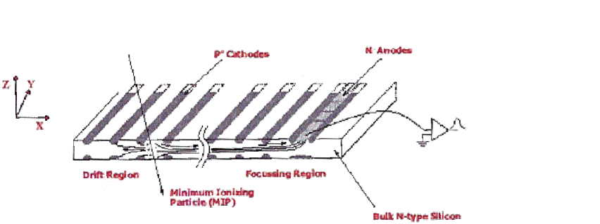
The principle of SDD’s is shown schematically in Fig. 9. Minimum-ionizing particles incident upon the detector produce electron-hole pairs, just as for silicon strip detectors. However, in the case of SDD’s, a pattern of azimuthal strips with a graded potential drifts the electrons axially to a focusing and collection region, which is segmented in azimuth to provide information. Complementary information is available from the drift time, giving the SDD a true 3-dimensional readout. Single-hit resolutions achieved with the STAR system are better than 10 m and 20 m in and respectively, with track separation resolution similar to that of silicon strip devices.
Silicon drift detectors offer tremendous background immunity for the LC environment. The pixel size, given for example by a 100 m strip pitch and 20 nsec digitization interval with a 6.5 m/nsec drift, would provide for pixels in the innermost layer of the LC detector. Tracks from minimum bias backgrounds can be rejected, as for the TPC, by the axial drift provided they are at least 3 JLC/NLC crossings (1 TESLA crossing) out of time. SDD’s are quite radiation hard, operating without degradation to a fluence of approximately neutrons/cm2, well in excess of the radiation dose expected for the LC.
One possible disadvantage of SDD’s, should ultra-precise momentum resolution be deemed to be an important tracking system goal, is their incompatibility with a long ladder implementation. The current material burden for the STAR system is approximately 1.4% per layer; with work, it may be possible to reduce this to 0.5% per layer. It should be pointed out that SDD’s have been operated in axial magnetic fields as high as 6 T, the baseline value for the ‘S’ detector alternative, with the only degradation being a 10-15% lower drift velocity due to magneto-resistance. There are concerns, however, about the effect of non-axial magnetic fields that arise as the boundary of the solenoid is approached.
Proponents of SDD technology for the LC envision a program of developing a 100 m pitch detector (250 m is now the standard) in hopes of achieving a single-hit resolution of 5 m. In order to reduce the material burden, they would like to explore the possibility of thinning the detectors from 300 to 150 m, optimization of the hybrid readout design, the use of gaseous rather than liquid cooling, and the migration from a 4 inch to a 6 inch wafer for detector production.
7 Specialized Gaseous Tracking Detectors
Numerous groups in the particle physics community have been working on the development of new types of gaseous tracking detectors, including Gas Electron Multiplier (GEM) detectors, Micro-mesh (Micromegas) detectors, and Micro-gap Wire Chambers (MGWC). Several of these may well find application in a LC detector for purposes of intermediate tracking, TPC readout, and timing layers.
The GEM detector consists of a matrix of holes in a thin (m) insulator sandwiched between metallic layers held at a potential difference of several hundred volts. Gas gain is localized within the region of the insulator, and residual ionization tends to be captured by the low-potential metallic layer. It is also possible to stack GEM detectors, leading to higher gains with greater ion feedback suppression.
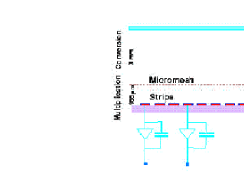
The Micromegas detector features a fine wire mesh separated by m (and several hundred volts) from an array of anode strips on an insulated substrate (see Fig. 10). A several-millimeter thick conversion region, with a smaller electrostatic field, provides a conversion layer for minimum-ionization particles, and a drift towards the gas multiplication region beyond the mesh. As for the GEM detector, the Micromegas detector suppresses the feedback of liberated ions back into the conversion and drift region, in this case via absorption by the mesh.
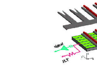
Finally, the MGWC consists of an array of anode wires separated from a plane of orthogonal cathode strips by a 10 m strip of insulator (see Fig. 11). Gas gain is achieved in the region surrounding the anode wire. The readout is two-dimensional.
Table 2 exhibits some of the performance characteristics of these three devices. As mentioned above, the GEM technology is a candidate for the LC TPC readout, for which having a gating grid is not feasible. With a 2 nsec temporal resolution, the MGWC might be a candidate for a timing layer external to the central tracking system. Finally, the high rate capability of these specialized gas detectors might make any one of them a candidate for the forward tracking system. Work continues on the development of these detectors.
| GEM | Micromegas | MGWC | |
|---|---|---|---|
| Gain | per layer | ||
| Spatial Resolution | 45 m | 70 m | |
| Energy Resolution | |||
| Timing Resolution | 15 nsec | 5 nsec | 2 nsec |
| Rate Capability | Hz/mm2 | Hz/mm2 | |
| Ion Feedback Supp. | per layer |
8 Forward Tracking
With the large emphasis on t-channel and peripheral processes, the forward tracking system is expected to play a critical role in many LC physics analyses. Initial studies of the performance capabilities of forward tracking have been done in the context of the North American ‘S’ detector, for which the forward tracking system is described below, and for the European detector design.
It has been found that, even for far-forward angles approaching (or 100 mrad, roughly the outer boundary of the mask), the momentum resolution is dominated by the curvature measurement (rather than the dip-angle measurement) over most of the relevant momentum range. This has led to the selection of double-sided silicon strip disks for the ‘S’ detector baseline, with opposing small angle stereo ( 20 mrad) on each side. A total of five disks (five U and five V measurement layers) are spaced evenly from the boundary of the CCD detector cryogenic containment to the endcap calorimetry, for a total extent from 30 to 150 cm. A spatial resolution of 7 m per measurement, and a material burden of 1% per layer, have been assumed. No concern has been given to the LC backgrounds at very small radius; should this prove to be problematic, it may be possible to use APS detectors for the innermost annulus of each disk.

Figure 12 exhibits the fractional momentum resolution for two different momenta (1 and 250 GeV) for the ‘S’ detector as a function of for mrad. It is seen that, assuming perfect detector alignment, such a system can measure the momentum to a relative precision of better than 10% over all values of momentum and . In particular, the charge sign determination is robust for even the smallest trackable angles.
9 Summary and Conclusions
Particularly for the central tracking detector, a number of possible alternatives appear viable for a detector that would instrument the interaction point of a high energy Linear Collider. For the central tracker, the desire to have excellent momentum and track separation resolution, as well as the highest possible degree of background immunity, leaves no obvious choice for the central tracker detector. It is essential that future physics studies be directed towards determining what relative priority each of these design criteria should have.
For the precise inner tracker, charge-coupled device (CCD) detectors seem to have somewhat of an advantage in resolution and material burden over active pixel sensor (APS) detectors. As discussed above, though, several issues need to be resolved before CCD detectors can be adopted to the exclusion of APS detectors. On the other hand, APS detectors may well be the most satisfactory option for far-forward, low radius tracking, and continued development of APS detectors along the lines summarized herein should be encouraged.
Far-forward tracking has been presented in the context of the North American ‘S’ detector, and looks promising in terms of its ability to perform a charge sign determination over the entire relevant range of momentum and . More sophisticated studies, including the effects of Linear Collider backgrounds, should be undertaken as early as possible.
Acknowledgments
The author would like to acknowledge the substantial help he received in writing this summary from the contributors to the Tracking and Vertexing session and from the organizers of the Sitges workshop. This work was supported in part by the Department of Energy, Grant #DE-FG03-92ER40689.
References
References
- [1] W. da Silva, these proceedings.
- [2] Track parameter uncertainties have been calculated with the routine LCDTRK, available from SLAC at http://www-sldnt.slac.stanford.edu/nld/.
- [3] K. Abe et al., Nucl. Instr. and Meth. A400, 287 (1997).
- [4] ATLAS Collaboration, Pixel Detector Technical Design Report, http://atlasinfo.cern.ch/Atlas/GROUPS/INNER_DETECTOR/PIXELS/tdr.html
- [5] S. Aid et al., ‘Detector for the Linear Collider’, Linear Collider Studies, Part E, DESY 97-123E, p. 509 (1997).
- [6] LCFI Collaboration, http://hep.ph.liv.ac.uk/ green/lcfi/lcfihome.html.
- [7] M. Krammer, H. Pernegger, Nucl. Instr. and Meth. A397, 232 (1997).
- [8] M. Pauluzzi (AMS Collaboration), Nucl. Instr. and Meth. 383, 35 (1996).
- [9] Bill Miller, HYTECH Inc., Los Alamos, New Mexico, USA, Private Communication.