The CLEO-III RICH Detector and Beam Test Results
Abstract
We are constructing a Ring Imaging Cherenkov detector (RICH) for the CLEO III upgrade for precision charged hadron identification. The RICH uses plane and sawtooth LiF crystals as radiators, MWPCs as photon detectors with TEA as the photo-sensitive material, and low-noise Viking readout electronics. Results of a beam test of the first two out of total 30 sectors are presented.
I Introduction
The CLEO detector is undergoing a major upgrade to phase III in parallel with a significant luminosity increase of the CESR electron-position collider[1, 2]. These improvements will make it possible to make precision measurements, especially of CP violation and rare B decays[3]. One of the main goals of the CLEO III upgrade is to have excellent charged particle identification.
In order to achieve this goal, we have designed and are constructing a Ring Imaging Cherenkov (RICH) detector, based on the ’proximity focusing’ approach[4]. It needs no optical focusing elements, and requires that the radiator is relatively thin compared to the distance of expansion gap between the photon detector and radiator. The detector can be designed flat and compact to fit in limited space. Our design is based on the pioneer work done by the Fast-RICH group[5, 6, 7].
When a charged particle passes through a medium, it radiates photons if the velocity of the particle is faster than light speed in the medium. The direction of the radiated photons with respect to track is given by , where is the index of the medium, and . To distinguish between hypotheses for a track at momentum , the formula is applicable.
In a medium of , a very fast particle () radiates Cherenkov photons at angle about 840 mrad. For CLEO III RICH design, our goal is to separate charged pions and kaons () at = 2.65GeV/c, the highest momentum that need be considered at CLEO for B decays. The Cherenkov angle difference of and at this momentum is 14.4 mrad . In order to obtain very low fake rate with high efficiency, we would like to achieve a separation between and at all the momenta relevant for B decays with the addition of a dE/dx contribution. This requires that the RICH provides 4.0 mrad Cherenkov resolution per track. Thus our benchmark is average 12 photoelectrons per track each with a resolution of 14 mrad.
II Detector Design and construction
The overall structure of the CLEO III RICH detector is cylindrical as shown in Fig. 1. It consists of compact photon detector modules at the outer radius and radiator crystals at the inner radius, separated by an expansion gap. The whole detector is divided into 30 sectors in the azimuthal direction. The RICH resides between the drift chamber and the electromagnetic calorimeter. The detector occupies a radial space between 80 and 100 cm in radius, is 2.5 m long, and covers 81% of the solid angle [2].
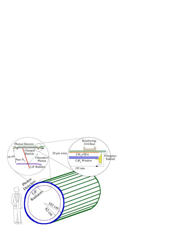
The choice of the material for the radiator and detector windows is driven by the choice of Triethylamine (TEA) as the photo-sensitive material. The gas mixture has a finite quantum efficiency in the VUV region (135-165 nm), which requires the use of fluoride crystals to insure transparency. The Cherenkov angle resolution is dominated by chromatic dispersion in the emission of light [8]. We choose LiF as radiator for its smaller chromatic dispersion in VUV region, of all the fluorides. The photon detector windows are made of .
The LiF radiators will be mounted on an inner carbon fiber cylinder as a array, each radiator is and 10 mm thick. The normal choice of radiator shape is a flat plate. However, as the total reflection angle of 150 nm photon in LiF ( at 150 nm) is about and the Cherenkov angle is close to , the photons radiated by track at normal incidence will be trapped as shown in Fig. 2. Instead of tilting the plates to allow the light to get out near the center of the detector, we developed radiators with a ’sawtooth’ pattern on its outer surface, which allows the Cherenkov photons to escape the radiator[8]. We will use such sawtooth radiators for the center four of the 14 rings.

The expansion gap (16 cm) is filled with high purity nitrogen gas. The volume is well sealed to minimize the contamination of and , which absorb VUV photons.
The photon detector is multi-wire proportional chamber with cathode pad readout. It is filled with gas bubbled through liquid TEA at (7%). The entrance windows are 2 mm thick , coated with 100 wide silver traces to act as an electrode. Photons with a wavelength between 135 nm and 165 nm can generate single photoelectrons in the mixture. The photoelectron drifts toward 20 diameter Au-W anode wires, where avalanche multiplication takes place. Charge is induced on an array of cathode pads, allowing a precise reconstruction of the position of the Cherenkov photon at the detector plane. The chamber is asymmetric, with the wire to pad distance of 1 mm and the wire to window distance of 3.5 mm, to improve the wire cathode pad coupling.
III Electronics
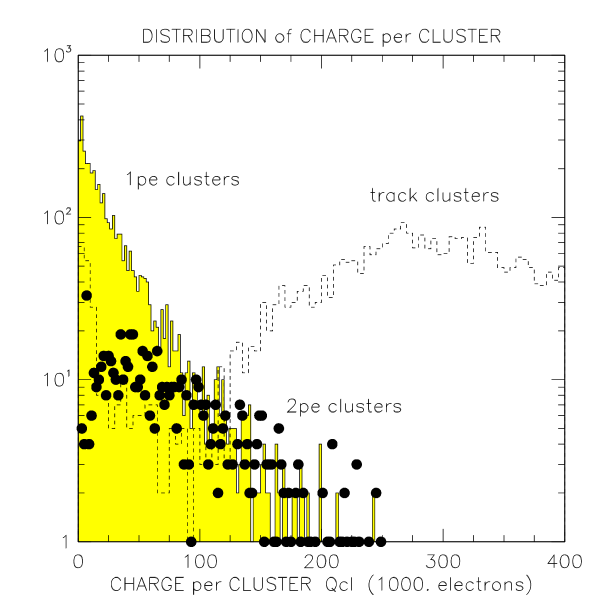
The choice of the readout electronics for CLEO III is governed by several Considerations [1]. First, the charge induced by a single photoelectron avalanche at moderate gain follows an exponential distribution as shown in Fig. 3. As the most likely charge is zero, it is necessary to have a very low noise system so that high efficiency is achieved. Furthermore, we want to reconstruct charged tracks accurately. We expect the pulse height from the charged track to be at least a factor 20 higher than the mean gain for a single photoelectron. In addition, high resolution analog readout allows a more effective suppression of cluster overlaps. Lastly, in the final system, we will have 230,400 channels to be readout. An effective zero suppression algorithm is necessary to have a manageable data size.
We use the VA_RICH chip as the front end processor. It is a custom-designed 64-channel VLSI chip based on the VA series developed for Si microchip readout [10]. It features low noise and large dynamic range. With a 2 pF input capacitor, its equivalent noise charge is about 150 electrons. Linearity is excellent up to input. Two chips are wire bonded to one hybrid circuit. Sixty hybrids are mounted on each photon detector.
The signal travels over a 6 m long cable from the detector to a VME databoard. The databoard includes receivers, 12-bit differential ADCs, bias circuitry for the VA_RICH chips, a circuit generating the timing sequence needed by the VA_RICH chip, and VME interface. In the final version, the databoards will include a DSP based algorithm for common mode subtraction that will make the system less vulnerable to coherent noise sources. For the beam test, 8 prototype databoards in one crate are used. These databoards were not equipped with coherent noise subtraction, and all the channels were readout to monitor and correct for coherent noise fluctuations.
IV Beam Test setup
In order to test our design of the RICH detector, a comprehensive beam test was performed. The beam test setup is shown in Fig. 4.
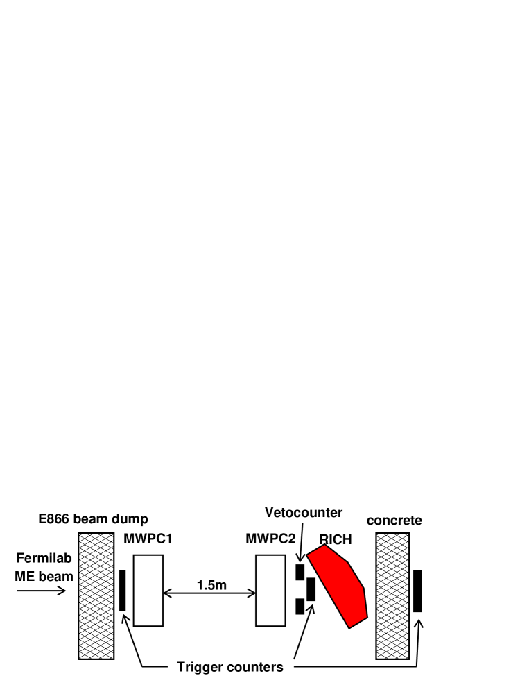
The first two photon detectors built for the final CLEO III RICH were mounted in an aluminum box. In addition, one plane and two sawtooth LiF radiators were mounted in the box at the same distance from the photon detectors as designed for CLEO III RICH. The box was sealed and flushed with pure nitrogen. A schematic of the box can be found in Ref. [9].
The beam test was performed in a muon halo beam in the Meson East area of FermiLab. Apart from the RICH itself, the system consisted of trigger scintillator counters, and a tracking system. We used two sets of MWPCs to measure the track position and angle. They provided 0.7 mm spatial resolution per station and a track angle resolution of 1 mrad. To simulate different track incidence angles, the RICH detector box was rotated at various polar and azimuthal angles.
V Beam test electronics performance
During the three week beam test, the photon detectors were run at an average gain of . The total electronic noise was about 1000 electrons. After coherent noise subtraction, the residual incoherent noise was 400 electrons, providing an average signal-to-noise ratio for single photon signal of 100:1.
An important effect that we discovered with the beam test was the temperature sensitivity of the analog +2V and –2V, necessary to bias the VA_RICH. Fig. 5 shows this effect. This, in turn, affected the bias configuration of the chip and its pedestal. The voltage regulator design has been changed to eliminate this problem.

VI Results
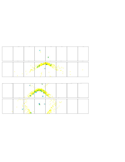
Fig. 6 shows the displays of two single events from the plane radiator at track incidence and from a sawtooth radiator at normal incidence. For the plane radiator, the image is a single arc as shown. While for the sawtooth radiator, two arcs on opposition sides of the charged track are visible, with the lower one truncated due to acceptance. The acceptance for images from plane radiators is about 85% of the maximum possible acceptance. With the necessary chamber mounts and window frames, 85% is the maximum possible acceptance. The acceptance for sawtooth images was about 50% in this setup, and should be about 85% in the final system.
Channels recording pulse height above a threshold of noise are selected for further analysis. The first step in the analysis is clustering. The center of the cluster is treated as the location of a photoelectron. About 2.2 pads per cluster are found, with 1.1 photoelectrons per cluster, due to some unresolved photon overlaps. For each photoelectron, the trajectory is optically traced back through all media, with the assumption that it originates from the mid-point of radiator. From this propagation path, the Cherenkov angle is calculated.
We extract the number of photoelectrons per track by fitting the single photon spectrum taking into account the background. We invoke a cut so as not to include non-Gaussian tails. The numbers of photoelectron per track at different incident angle are shown in Fig. 7 (a). For plane radiator, the average number of photoelectrons per track is between 12 and 15, varying with incident angle. For the sawtooth radiator the number is lower due to limited acceptance. An extrapolation made to estimate the performance of the final system predicts 17-20 photoelectrons. Fig. 7 (b) shows the measured Cherenkov angle resolution per photon . The resolution is between 11 and 15 mrad.

The parameter that shows the particle identification power of this system is the Cherenkov angle per track . The resolutions are summarized in Fig. 8 for both plane and sawtooth radiators. The measured increases with track angle[8]. A Monte Carlo study is performed to simulate the resolution. The Monte Carlo represents the plane radiator data well. For the sawtooth radiator, the data show a worse resolution than the simulation. There are several sources in the simulation that could account for this discrepancy, such as the tracking error, beam background, and imperfect knowledge of the sawtooth shape.

The Monte Carlo study also shows that the contribution to from the tracking errors is significant, especially for large incident track angles. This error comes in due to the photon emission point error. For the plane radiator at , the contribution is about 4 mrad, while the total error is about 5.8 mrad. In the final CLEO III system, the tracking system is expected to be substantially better than the system used in the beam test. In order to have approximate projection of the performance of the CLEO III RICH, we extrapolate the resolution from the beam test results, with the assumption of no tracking error and the acceptance in final system. This resolution is shown as the filled circles in Fig. 8.
VII Summary and outlook
The beam test results indicate that the specifications of CLEO III RICH design are fulfilled. In particular, the Cherenkov angle resolution per track reaches 4 mrad, which will provide separation in CLEO III [11]. The RICH detector is on the final stage of construction. We expect the completion of the project in Summer 1999.
VIII Acknowledgments
We would like to thank FermiLab for providing us with necessary infrastructure and dedicated beam time. We give particular thanks to Chuck Brown and other colleagues from E866 for their hospitality.
REFERENCES
- [1] M. Artuso, Nuovo Cim. 109A, 1035 (1996).
- [2] S. Kopp, Nucl. Instr. Meth. A384, 61 (1996).
- [3] S. Stone, Nucl. Instr. Meth. A368, 68 (1995).
- [4] T. Ypsilantis et al., Nucl. Instr. Meth. A343, 30 (1994).
- [5] R. Arnold et al., Nucl. Instr. Meth. A314, 465 (1992).
- [6] J. L. Guyonnet et al., Nucl. Instr. Meth. A343, 178 (1994).
- [7] R. Mountain et al., Nucl. Instr. Meth. A360, 400 (1995).
- [8] A. Efimov et al., Nucl. Instr. Meth. A365, 283 (1995).
- [9] G. Viehhauser et al., Nucl. Instr. Meth. A419, 557 (1998).
- [10] E. Nygard et al., Nucl. Instr. Meth. A301, 506 (1991).
- [11] More details can be found in R.J. Mountain et al., “The CLEO-III Ring Imaging Cherenkov Detector,” Invited talk by at “The 3rd International Workshop on Ring Imaging Cherenkov Detectors,” a research workshop of the Israel Science Foundation, Ein-Gedi, Dead-Sea, Israel, Nov. 15-20, 1998, (hep-ex/9902023).