Development of a Scintillating Fibre Detector for HERA-B
Abstract
A fibre detector with multianode PM readout for high rate applications was developed for the HERA-B spectometer to cover the area near the beampipe. Such a detector has to operate at particle rates up to and has to tolerate a radiation dosis up to 1 Mrad/y. The light output of test detectors with different scintillating fibres was measured as well as the light transport through clear fibres to the PM as a function of radiation dosis and different conditions of irradiation. The geometry of the detector is described and results for a full size prototype are presented.
1 Introduction
The HERA-B experiment, presently under construction at DESY, Hamburg, is designed to measure CP violation in the B-system. Neutral B-Mesons are produced by interactions of 820 GeV protons on a stationary (carbon) target. Only about 1 out of interaction produces a pair. HERA-B therefore plans a total interaction rate of 40 MHz leading to very high particle fluxes and high radiation levels in the detector. The particle flux is about at 6 cm vertical distance from the beam and drops roughly as . The innermost part of the tracking system ( inner tracker ITR) which covers a range cm and cm is therefore a big challenge for the tracking detector technology. The detectors have to sustain a particle flux up to and a radiation dosis up to 1 Mrad/year.
The baseline design for the inner tracker of HERA-B used Microstrip Gas Chambers (MSGC), where 4 L-shaped detectors covered one detector plane around the beam pipe. This detector technology faced very severe operation problems in intense hadron beams as first shown in a beam test at PSI [1]. Heavily ionising particles induce gas discharges which destroy the electrodes if operated at useful gas gains of about 2000. Since this problem could not be solved fast, we were forced to also investigate alternative detector concepts. The use of scintillating fibre detectors for the inner tracker looked as an interesting possibility and was therefore followed up to a full size prototype.
2 Geometry of a fibre tracking detector for HERA-B
The following requirements are necessary to satisfy the needs of HERA-B .
-
•
A detector plane needs 95% efficiency for a minimum ionising particle.
-
•
The occupancy of one detector element should not exceed 6% at 40 MHz interaction rate. This requires a granularity of readout of .
-
•
The active area should be identical to the original MSGC geometry in order to fit to the overall detector concept.
-
•
We need fast readout. The analog readout needs a pulse shaping of . In addition the detector has to deliver level one trigger signals for each bunch crossing (every 100 ns). We therefore opted for multianode photomultipliers.
-
•
The scintillating light of each detector element has to be transported to the outside of the sensitive tracking area up to the photomultipliers over distances between 1.0 to 3.5 m.
Figure 1 shows a typical geometry for one fibre tracking station with the arrangement of PM’s and clear fibre light guides. Figure 2 shows the fibre geometry of the detector which was chosen to meet these requirements. The detector is buildt from double clad fibres with an outer diameter of .48 mm. In order to guarantee high efficiency, 7 fibres which are positioned behind each other along the beam direction form one readout road. They are coupled to a single clear fibre (1.7 mm diameter) and are read out by one photomultiplier pixel. Neighbouring fibre roads overlap by choosing a pitch of 340 . This guarantees that a minimum ionising particle with angle w.r.t. vertical impact traverses at least 2.5 mm of scintillator. One detector plane has then 704 readout roads. The scintillating fibres are coupled to clear fibres using custom designed connectors made of acrylic plates.
Compact multianode photomultipliers (Hamamatsu R5900-M64) were forseen for photon detection. These 14 stage tubes house 64 anodes with pixel sizes at the cathode of and have a bialkali photocathode. This tube was specifically developed for the HERA-B project. The clear fibre diameter of 1.7 mm is the maximum possible for this PM to match it to one pixel and to keep optical cross talk of neighbouring pixels below 1 %. The 7 fibres within one road are therefore also the maximal number which can be read out by one pixel.
3 Estimate of light yield
In order to get an efficiency above 95% for a minimum ionising particle we have to detect at least 3.0 photoelectrons in one road in average assuming we can rely on
single photoelectron events or 4.7 photoelectrons if we need at
least 2 photoelectrons for safe
particle detection. This light level has to be guaranteed over the life time of
the experiment, e.g. up to a total radiation dosis of about 3 Mrad for the
innermost part.
The following options were considered and experimentally tested.
-
•
scintillating fibres: We tested double clad scintillating fibres from three companies (Kuraray, Bicron and PolHiTech) and different emission wavelength. Blue fibres with maximum emission around 450 nm are best matched to the quantum efficiency of the bialkali photocathode but blue light is rather strongly absorbed in the clear fibres especially after exposure to radiation. Green (3HF) fibres with maximum emission around 540 nm are known to be more radiation hard [2], green light shows small absorption in the clear fibres but is poorly matched to the cathode efficiency. Finally we have also tested fibres in the blue-green emission region nm).
-
•
clear fibres: Double clad fibres of all three companies were tested. Transmission of the light from different scintillators was tested as a function of fibre length and radiation dosis.
-
•
The scintillating fibres have a typical length of 35 cm. In order to increase the light yield and minimize absorption effects we tested different reflectors at the fibre end.
-
•
The optical couplings between scintillating and clear fibres and to the PM were systematically tested.
Figure 3 shows the relative number of photoelectrons for new fibres which was calculated on the basis of published data for fibres and photomultiplier after 0.1 m, 3 m and 5 m of clear fibre. Blue and green fibres were expected to deliver more than 15 resp. 9 photoelectrons after 3 m of clear fibre which gave hope that such a detector could deliver enough light even after radiation damage. Green fibres looked promising because it was expected that the light yield though smaller at the beginning would be more robust against irradiation. A green fibre solution is very attractive if one uses a photon detector with high quantum efficiency at long wavelength as used e.g. by D0 [2]. Unfortunately it turned out to be impossible to produce multianode photomultipliers with green enhanced photocathodes with sufficient homogenity.
4 Measurements of relative light yield as a function of radiation dosis
The relative light yield for the HERA-B geometry and readout was measured in the laboratory using electrons from a strontium source for different combinations of scintillating and clear fibres before and after irradiation .
4.1 Experimental setup
Fibre bundles of the correct geometry but only 3 scintillating fibres in one readout row and with a width of typically 2 cm were assembled using different glueing techniques. The length of the scintillating fibres was 35 cm, they were glued together over a length of about 25 cm, the typical length of a HERA-B detector. The three fibres in a row were then coupled to a clear fibre (typically 3 m long) and read out by a multianode photomultiplier (Hamamatsu R5900-16) which had the same quantum efficiency as the PM forseen for the final readout. The Sr source was collimated and high energy electrons were selected by a twofold coincidence of narrow scintillator counters below the fibre bundle. This arrangement guaranteed that the electrons pass through the fibre bundle but not necessarily within one road. We therefore coupled the clear fibres of 7 neighbouring roads to a single pixel. The pulseheight was recorded with a flash ADC system for every single trigger. Since the number of photoelectrons was typically small the analysis was done by determining the average number of photoelectrons from the measured spectra by folding single electron spectra using Poisson probability.
The coupling between scintillating and clear fibres was done with specially designed connectors which allowed reproducible light coupling to better than 7%. It was therefore possible to measure the relative light yield of different fibre bundles or of one fibre bundle after different steps of irradiation reliably using the same setup of fibres and readout channels.
The irradiation of fibres was done using a strong source of BASF company, Ludwigshafen. This source allows a radiation dosis of 50 krad/h at a distance of 5 cm and is surrounded by a large irradiation volume. By placing the fibres at a proper distance from the source the dosis per unit time could be adjusted from 1.2 Mrad per day to 10 krad per day. This possibility was e.g. used to position the clear fibres in such a way that they were irradiated according to the expected relative dosis along their length in HERA-B . The light yield was not recorded during irradiation but could normally only be measured about 2 hours after the end of irradiation.
4.2 Production of fibre bundles
The fibre bundles were produced by hand using a machined Al template with grooves at a distance of 740 which defined the position of the first layer of scintillating fibres. Successive layers were then positioned by the layer below. The fibres were glued together using standard acrylic water based glue except for the fibre ends which were mostly embedded in epoxy glue for better machining. This simple procedure produced rather regular structures. Different types of glueing techniques have been used. For our standard fibre bundles the fibres were glued together with transparent acrylic glue only in few narrow strips perpendicular to the fibres. This guarantees that air can access the fibres during irradiation. We also produced bundles where the fibres were completely embedded in white acrylic glue. This white glue prohibits any optical cross talk between the fibres within the bundle and also changes to some extent the overall light yield.
4.3 Tests of mirrors and connectors
In a first step we tested the reproducibility and effectiveness of connectors and mirrors. The connection between scintillating and clear fibres is done using an air gap. The use of optical grease was also tested but improved the light yield by only 10% which does not justify the other risks. Both types of fibres were glued into the inner tube of a brass connector using epoxy glue. The surface at the fibre ends was then milled and polished. The two parts of the connector could then be screwed together guaranteeing a well defined position and distance of the fibres. The transmission of these connectors was determined to be greater than 80% and this transmission was reproducible to better than 5%.
At the end of the fibre bundle (opposite to the readout) the scintillating fibres were glued together using epoxy glue and then milled. The absorption within the 35 cm of fibre length is not negligible especially after irradiation. We therefore planned to use a mirror to the end. The best mirror turned out to be a sheet of aluminium which was coupled to the end of the bundle using optical grease. Polishing of the fibre ends did not lead to improvements. Using this simple method we reached good reflectivity resulting in an increase of light output by a factor 1.75 which turned out to be well reproducible.
4.4 Relative light yield of scintillating fibres as a function of radiation dosis
Various fibre bundles were produced using the same glueing technique and were coupled to the PM using always the same clear fibre bundle (Kuraray). Table 1 gives a summary about the materials which have been used.
| company | fibre | wavelength | |
| scintillating fibres | |||
| Kuraray | SCSF-78M | 450 nm | radiation hard |
| Bicron | BCF12 | 440 nm | |
| PolHiTech | 0246B | 450 nm | |
| Kuraray | 3HF(1500)M | 540 nm | radiation hard |
| Kuraray | PMP450 | 450 nm | test sample |
| Bicron | BCF 60 | 540 nm | |
| clear fibres | |||
| Kuraray | clear fibre | ||
| Bicron | BCF98 | ||
| PolHiTech | PolifiOP-2-120 |
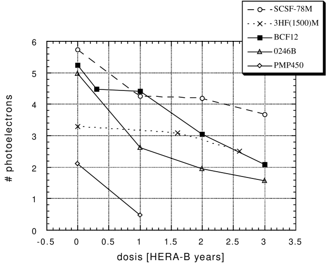
After several reference measurements the fibre bundles were exposed to radiation starting with 300 krad and then in steps of 1 Mrad where this dosis was applied within 14 hours e.g. at a radiation level of about 50 krad/h (100 times faster than in HERA-B ). The light yield was measured after every step. The results are shown in figure 4.
New fibres show very different number of photoelectrons. The best yield is obtained using Kuraray SCSF-78M blue fibre followed by Bicron and PolHiTech blue fibres. Green 3HF fibres as expected have a rather low number of photoelectrons due to the low quantum efficiency of the PM for green light. The different fibres show rather different sensitivity to radiation. A common feature is however, that a good fraction of the light loss appears already after 0.3 resp. 1 Mrad. Fibres with PMP which were produced as a test sample by Kuraray are destroyed completely after rather small irradiation. Blue Kuraray fibres loose about 36% of their light yield after 3 Mrad, whereas the Bicron BCF12 fibres loose 66 % and the PolHiTech fibres 0246B 68%. This light loss is entirely caused by a shortening of the absorption length in the scintillating fibre as can be demonstrated by the change of light yield along the length of the fibre bundle. The green 3HF fibres loose only 20% and are thus relatively robust against radiation as expected and reported before [2].
The light yield was monitored over a long period to see if scintillating fibres recover from radiation damage. Under our conditions of rather fast irradiation no recovery was observed over a period of typically 40 days for fibre bundles which were only partially glued and therefore allowed air circulation.
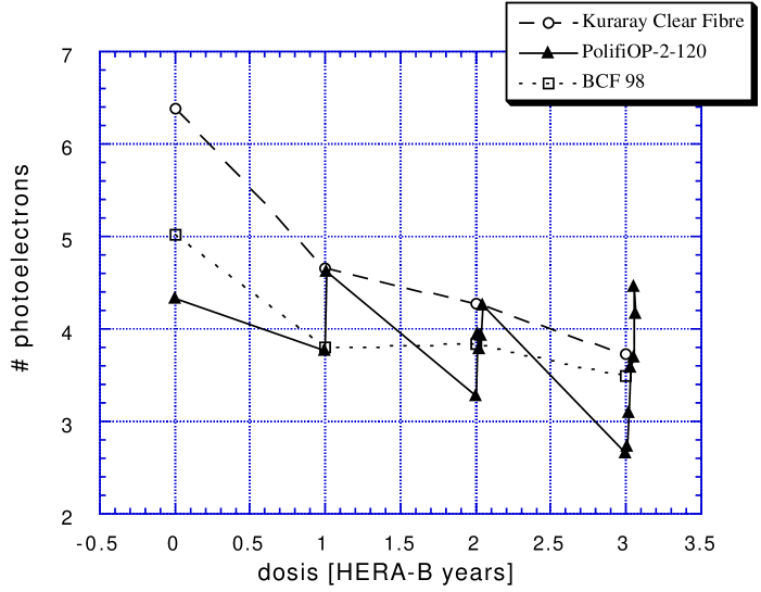
4.5 Transparency of clear fibres
The relative transparency of clear fibres from all three companies was measured as a function of irradiation using always the same unexposed scintillating fibre bundle (Kuraray blue SCSF-78M fibres). The clear fibres were positioned in the irradiation volume in such a way that the ’natural’ irradiation of HERA-B was simulated which starts with 300 krad/year at 30 cm distance from the beam pipe and comes down to 10 krad/year at a radial distance of 3.0 m. The results are shown in figure 5. Clear Kuraray fibres have by far the best transparency for blue light before irradiation. After an irraditation corresponding to 3 years of HERA-B however they have lost 40% of transparency and all three fibres are about equal on first sight. Kuraray and Bicron clear fibres show essentially no recovery from radiation damage. In contrast the PolHiTech fibres show very strong recovery with time scales up to 700 hours. These fibres can recover to full transparency if one waits long enough. Since they start however with a transparency which is only 2/3 of the Kuraray fibres they are finally more or less equally good. Again the loss of transparency is related to a change of absorption length in the clear fibres.
It was originally hoped that the use of green 3HF fibres would profit from a better transparency of the clear fibres after irradiation. This is in principle true however not for our readout with photomultipliers. Green fibre bundles in combination with clear fibres showed the same total loss in the number of photoelectrons as blue fibres. The reason for this is, that the light which is transmitted up to the photocathode after irradiation is shifted to longer wavelengths which leads to a reduced quantum efficiency at the photocathode and therefore a reduced number of photoelectrons. This compensates the advantage of better transparency in the clear fibres. Green fibres are therefore not a viable choice.
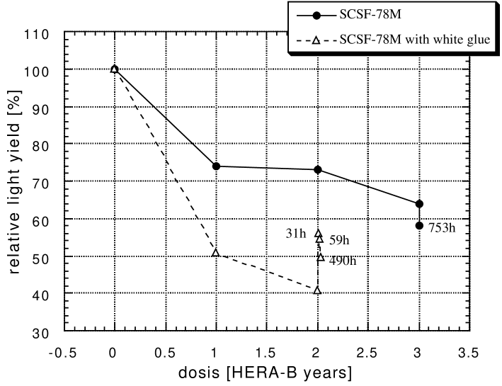
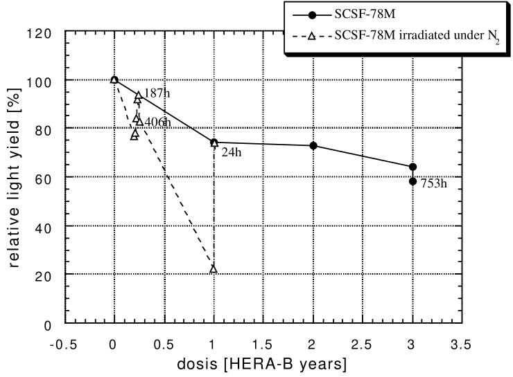
5 Radiation damage of fibres under varying conditions
The loss of light yield for a fibre detector at HERA-B is expected to be very severe according to the results presented so far. We have therefore made auxiliary tests to see if the radiation damage can be reduced or if better recovery can be obtained. These tests included different glueing techniques for the fibre detector, irradiation in and studies of radiation damage as a function of dosis rate. Figure 6 compares the relative light yield of a standard fibre bundle using blue Kuraray fibres and partial glueing of the fibres with a bundle where the same fibres were fully imbedded in white arylic glue. The radiation damage for the detector with white glue is substantially larger but it shows partial recovery from radiation damage over time periods of about 60 hours. Figure 7 compares the loss of light yield for two standard Kuraray SCSF-78M detectors (partially glued) where one was irradiated under air the other in nitrogen atmosphere. The light loss for the bundle which was exposed in is much larger if measured immediately after irradiation. However if this bundle is exposed to air then the light yield partially recovers over time periods of about 24 hours to a value still lower than what is obtained after irradiation in air. These results clearly indicate that oxygen plays a major role for radiation damage and recovery. Under our conditions of relatively moderate dosis rates these results may be interpreted in the following way: for fibres which are exposed under air and where the fibres are easily accessed by air (fibres not fully embedded in glue) the radiation damage seems to recover partially already during irradiation. These bundles therefore show no subsequent recovery. atmosphere does not allow recovery and therefore leads to stronger damage. Clear Kuraray fibres show no significant difference if irradiated in atmosphere compared to air.
We have finally made some tests to study how the radiation damage depends on the rate of irradiation. For Kuraray scintillating and clear fibres no rate dependence was observed for rates between 100 krad/day and 1 Mrad/day if the irradiation was in air. The PolHiTech clear fibres on the other hand demonstrated a very complicated behaviour. Even very modest irradiations led to a large loss of light yield which however recovered fully after some time. We have no safe way to judge how these fibres would behave under the slow irradiation in the HERA-B experiment.
6 Prototype detector
A full size prototype fibre detector was manufactured by Kuraray company using SCSF-78M scintillating fibres with a diameter of .48 mm according to the geometry of figure 2. The fibres of one row (mostly 7 fibres) were bundled in a 1.5 mm hole of the connector which was produced from an acrylic plate. Optical inspections on a measuring table showed that the accuracy of perpendicular fibre position over the whole area of the detector is better than . This detector was also tested in an electron test beam [3] with rather good results.
In conclusion the production of such a fibre detector is industrially possible with adequate quality.
7 Beam test results and absolute light yield for a HERA-B fibre detector
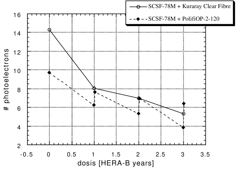
The total light yield for the best combinations of scintillating and clear fibres as measured in the laboratory are shown in figure 8 extrapolated to the full detector thickness of 7 fibres in a row. Whereas about 14 photoelectrons are expected for new fibres, this number is reduced to 5.5 after 3 years of operation. It should be noted that these numbers are upper limits for the number of photoelectrons for the HERA-B detector because the low energy electrons from the strontium source will normally scatter and thus have a longer effective path in the scintillating fibres compared to high energy minimum ionising particles. It is therefore important to determine the absolute number of photoelectrons in a high energy test beam which also allows to measure geometric effects like the sharing of light between neighbouring roads, cross talk and the number of photoelectrons due to low energy background and Cherenkov light in the clear fibres.
These measurements were done in an electron test beam (5 GeV) at DESY by our collegues from Zeuthen [3] and in the HERA-B experimental area. It turned out consistently that the laboratory measurements with a source strongly overestimated the number of photoelectrons. A new fibre detector as forseen for HERA-B using blue Kuraray SCSF-78M fibres and Kuraray clear fibres of 3 m length gave only 7 photoelectrons for one minimum ionising particle. After 3 years of operation this number could then drop to only 2.75 photoelectrons according to the radiation damage measurements. In addition it turned out that the number of fibres which showed accidental signals was huge. These signals are essentially all single photoelectron signals which are produced by soft particles, optical crosstalk in the fibres and Cherenkov light in the clear fibres ( 50%). For efficient tracking and the derivation of trigger signals we have therefore to require at least 2 photoelectrons per minimum ionising particle. An efficiency of the detector of 95% under these conditions requires at least 4.0 photoelectrons per minimum ionising particle which cannot be guaranteed after irradiation.
8 Conclusions
Our measurements of light yield were done in a way to get the most direct evaluation of a fibre detector as needed for HERA-B . More generic and systematic tests of the same materials have been carried out by our collegues at Zeuthen [3]. They also answered the very important question if our results obtained with gamma ray irradiation are representative for the irradiation with hadrons and neutrons which would happen in the HERA-B experiment. For this purpose they compared radiation damage induced by proton and electron irradiation for the same dosis. It turned out that the long term damage is identical, irradiation is therefore representative also for the radiation damage induced by a hadron beam.
Our test results show that a fibre detector as described in section 2 would satisfy the needs of the HERA-B detector at the beginning. The expected radiation damage of scintillating and clear fibres under the conditions applied in our tests is however so large that such a detector would have reduced efficiency already after one year of operation. It has to be pointed out however, that our results on radiation damage have been obtained by applying a rather large radiation dosis over a relatively short time period (typically 50 krad per hour). There is no proof that the same damage would occur at HERA-B with a dosis rate of typically 0.4 krad/hour. It cannot be excluded that the damage at HERA-B would be substantially different.
Based on the available information we had to conclude however that safe operation over several years of HERA-B running could not be guaranteed. This fact in combination with the very high price tag for such a detector led to the decision to abandon this technology for HERA-B .
Acknowledgement
We acknowledge the support of Dr. Seher and Mr. Mosbach from BASF company, Ludwigshafen, which allowed us to use the source for the irradiations of our fibres. This work profited strongly from collaboration with our collegues from the Institut für Hochenergiephysik in Zeuthen [3] in the area of fibre detectors and beam tests and from the university Siegen (A. Lange, U. Werthenbach, G. Zech and T. Zeuner) which carried out the tests of the multianode photomultipliers. This project is supported by the Ministerium für Bildung, Wissenschaft, Forschung und Technologie, Bonn.
References
- [1] B. Schmidt, MSGC development for HERA-B, 36th workshop of INFN Eloisatron Project on new detectors, Erice, nov. 1997, physics/9804035 30 Apr 1998.
-
[2]
R.C. Ruchti, Annu. Rev. Nuc. Part. Sci., 1996 46, 281-319
Bross. A.D., Nucl. Phys. B (proc. Suppl.) 44, 12 (1995) - [3] E.C. Aschenauer et al., DESY 98-001 and R. Nahnhauer, private communication


.