Development of a Large-Area Aerogel Čerenkov Counter Onboard BESS
Abstract
This paper describes the development of a threshold type aerogel Čerenkov counter with a large sensitive area of to be carried onboard the BESS rigidity spectrometer to detect cosmic-ray antiprotons. The design incorporates a large diffusion box containing 46 finemesh photomultipliers, with special attention being paid to achieving good performance under a magnetic field and providing sufficient endurance while minimizing material usage. The refractive index of the aerogel was chosen to be . By utilizing the muons and protons accumulated during the cosmic-ray measurements at sea level, a rejection factor of was obtained against muons with , while keeping 97% efficiency for protons below the threshold.
keywords:
BESS, cosmic-ray antiproton, particle identification, aerogel Čerenkov counter, diffusion box, finemesh photomultiplier tube., , , , ,
1 Introduction
In three consecutive scientific flights over northern Canada (1993–1995), the balloon-borne BESS rigidity spectrometer, which has a large acceptance of , precisely measured the rigidity, velocity, and dd of cosmic-ray antiprotons. The first definite (mass-identified) detection of low-energy antiprotons was achieved [1] by using BESS’93 data in the kinetic energy range from to . By improving the time-of-flight (TOF) resolution, the BESS’95 data further led to background-free detection of antiprotons in the range from to [2]. The resultant energy spectrum appeared flat below , where the production of secondary antiprotons in interstellar space is expected to sharply decline. Although such phenomena could very well indicate the existence of an admixture of primary antiprotons from novel sources [3, 4] such as the evaporating primordial black holes or the annihilation of neutralino dark matter, present statistical accuracy and the limited energy range do not allow us to draw a firm conclusion due mainly to the uncertainties in the calculation of secondary antiprotons.
As a means of confirming whether or not a primary antiproton signal does exist, the absolute flux of secondary antiprotons must be determined by expanding the detection range up to about kinetic energy; a range covering the expected peak (at ) in the secondary antiproton flux, which is generally considered to be the predominant source of antiprotons.
Independent to the search for the novel primary antiproton component, the precise measurement of the secondary antiprotons itself will be of crucial importance to determine the propagation mechanism of cosmic rays in the Galaxy.
Based on above scientific considerations, one of us proposed [5] achieving background-free and positive (mass-identified) detection of antiprotons up to by (i) eliminating the overwhelming background with a threshold-type aerogel Čerenkov counter having proper refractive indices around 1.03, and (ii) improving the timing resolution of each TOF counter to .
In this paper, the design, construction, and performance of the aerogel Čerenkov counter are presented.
2 General description
2.1 Configuration onboard BESS ’97 spectrometer
Figure 1 shows a cross-sectional diagram of ’97 version of the BESS rigidity spectrometer (for detail, see [1, 6]) consisting of a superconducting solenoidal magnet with a central nominal field of 1 T, inner drift chamber (IDC), JET drift chamber, TOF plastic scintillation hodoscope, and aerogel Čerenkov counter. Onboard accommodation of the aerogel Čerenkov counter was achieved by positioning it between the upper TOF hodoscope and cryostat.

2.2 BESS aerogel Čerenkov counter
In describing the developed counter, cylindrical coordinates are used in which the magnetic field direction is taken as the z-axis and the perpendicular plane as the plane. The following design constraints were applied to the counter.
-
1.
The counter should have a large solid angle and area such that it matches the large acceptance of the BESS spectrometer.
-
2.
The counter should have a thickness of .
-
3.
The counter should operate in the fringe magnetic field of .
-
4.
To determine the threshold of antiprotons to about , the aerogel refractive index () should be .
-
5.
The rejection factor between antiproton and background should be at least in order to have background-free detection of antiprotons.
-
6.
The integrity of aerogel blocks should be maintained against shock and vibration during shipping, launching, and parachute landing.
To verify that design constraints (1)– (6) could be satisfied, we built a prototype counter incorporating 14 finemesh photomultiplier tubes (PMTs) at each end, being about one-fourth in size relative to the envisioned counter. Measurements of cosmic-ray muons were taken such that various configurations could be examined to optimize reflector material, the placement of slanted end plates on which the PMTs would be mounted, and aerogel thickness.
Figure 2 shows an overview diagram of the final design, where the counter consists of a large diffusion box containing aerogel blocks viewed by PMTs densely arranged at the both ends. The unit’s weight and the amount of material were minimized using an aluminum-core honeycomb plate as the main structure.

Choosing an effective reflector material is a key aspect in counter design since most photons generated in the diffusion box will undergo numerous reflections prior to reaching the PMTs. We accordingly tested various type of sheet material, i.e., Millipore, Tibex, and Goretex; ultimately finding that Goretex, which exhibits high reflectivity in the short-wavelength region (–), is most suitable. From the standpoint of photon collection, this is consistent with the fact that the number of Čerenkov photons is inversely proportional to the square of wavelength; thereby making reflectivity in the short-wavelength region important.
In consideration of operating the counter in a - fringe magnetic field, we selected -inch-diameter finemesh type PMTs (R6504S, Hamamatsu Photonics K. K.) whose sensitive region lies between and . Readout electronics consists of summing amplifiers that combines 46 PMT signals into 8 channels, which are digitized by a charge-integrated ADC. Blue LEDs (NLPB, NICHIA) with a peak of are used to adjust the PMT gain such that all the PMTs provide the same ADC counts per photoelectron. Since PMT gain shows magnetic field dependence, final high-voltage tuning must be done in the counter after exciting the solenoidal magnet to the nominal field. Therefore, the blue LEDs were mounted on the both sides of the side plate at its center point; a configuration allowing PMT gain to be monitored throughout the experiment.
Another consideration concerns the magnetic field itself, since if the PMT axis and magnetic field direction form a nonzero angle , then the PMTs lose their effective photocathode area (), i.e., some secondary electrons produced at dynode, traveling inside the PMT in the direction of the magnetic field, cannot reach the anode. Accordingly, to avoid losing , each end plate on which PMTs were mounted was slanted to reduce . The drawback in this approach, however, is that slanting in turn leads the loss of photoelectrons. It is for this reason that during prototype testing we focused our attention on optimizing the angle of slanting such that photoelectron loss is at an acceptable level. The slanting angle was determined to be after optimizing photoelectron loss and . This slanting angle reduced from to about in the lower PMTs and from to about in the upper PMTs, while increased by 20% in comparison with not slanting. A mask of Goretex was placed over the front surface of each PMT (Fig. 2) such that the photons hitting the insensitive photocathode area formed by residual would be reflected back.
2.3 Aerogel
As a Čerenkov radiator, we selected silica aerogel (Mori-Seiyu Co.) having a refractive index of 1.032, which was optically measured in several pieces of sample using a He-Ne laser with wavelength of 632.8 nm [7]. This aerogel was manufactured using a new method [7] which ensures that it retains its hydrophobicity such that long-term stability and good clarity are afforded. It is the aerogel’s excellent clarity that allowed us to use a diffusion versus mirror box design despite being constrained by a counter thickness of .
Transmission of the aerogel samples were measured using a photospectrometer [7]. The obtained data was translated into the transmission length () by the function:
where , and are the transmission and thickness of aerogel, respectively. Figure 3 shows a typical sample of wavelength dependence of the transmission length for a 2.1-cm thick sample. The transmission length strongly depends on the wavelength.

The aerogel’s unique hydrophobicity enabled it to be manufactured by a water-jet cutter to the correct size with an accuracy of . Each block of aerogel was cut with a slight taper along its width (toward the direction) in order to minimize gaps after assembly.
Aerogel can be configured by either suspending blocks of it from the top plate or attaching blocks to the bottom plate. We had surmised that the former configuration would lead to detecting a higher number of photoelectrons, although aerogel fixation would be relatively more difficult. However, prototype testing showed no significant difference in the measured number of photoelectrons for the two cases; thus we attached aerogel blocks to the bottom plate. PMTs were mounted on the upper part of each end plate since in prototype testing this configuration detected about 10% more photoelectrons versus a configuration in which PMTs directly viewed the aerogel blocks.
Onboard space limitations dictated the design constraint of a -cm-thick counter. The prototype tests showed that when the thickness of aerogel reached half that of the counter, the measured number of photoelectrons was at saturation; whereas at three-fourths thickness, the number decreased due to aerogel absorption of photons. With these results in mind, and since our main target is low-energy antiprotons, the aerogel thickness should necessarily be as thin as possible in terms of quantity of material used. At a density of , the thickness of the aerogel blocks was determined to be .
Figure 4 shows how an aerogel block was made, i.e., a stack of four -cm-thick layer pieces with a piece of Goretex sheet on their bottom were wrapped lengthwise with polyethylene film (ITOCHU SANPLUS Co. Ltd.). Then, after placing cardstock paper on the bottom side, it was again wrapped around its width. Polyethylene film was chosen as it has good clarity in the relevant wavelength region. A string made of Kevlar was used to fix (tie) the aerogel block to the bottom honeycomb plate through a hole drilled on it. With this configuration of block fixation, no photon-absorbing surfaces such as aluminum support surfaces are present within the diffusion box.

When assembled, the aerogel blocks form upper and lower surfaces of and , respectively.
3 Performance
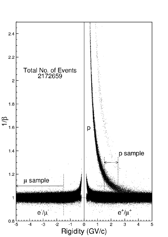
Counter performance was evaluated using cosmic-ray data collected with the full BESS’97 configuration at sea level over a 4-d period in May 1997. Figure 5 shows the obtained scatter plot of versus spectrometer rigidity, where proton () and muon () bands are clearly separated up to , being identified by rigidity and TOF measurements (mass determined).
3.1 Counter response
From sea level data of negatively charged muons in the rigidity range of and , we evaluated the response of the counter at .
Figure 6(a) shows the charge (ADC) distribution (histogram) obtained around the center of the counter for vertically incident muons. By fitting data in region 0 to 260 counts to an approximation [8] of a Poisson distribution, the effective [9, 10] mean number of photoelectrons () was determined to be .

The position and angle dependence of the incident particle was measured over the counter’s sensitive region. Figure 6(b)–(d) shows versus path length in aerogel (), , and , respectively. These figures indicate that is proportional to , and that is dependent on of the incident particle whereas dependence of the counter is small. Note that only slight decreases of are present at the positions corresponding to the gaps between assembled aerogel blocks. The influence of these gaps can be totally eliminated during the offline analysis stage using geometrical cutting while maintaining the cut efficiency at more than 99%.
In order to select the particles which passed through the aerogel, we applied the fiducial cut by requesting that the extrapolated track should cross the upper as well as lower surface of the aerogel. The open histogram in Fig. 7 shows the counter’s response throughout its sensitive region to muons at , which allows the rejection factor of the antiproton background to be estimated. We also studied the response of the counter to below-threshold particles. The hatched histogram in Figure 7 shows the charge distribution for protons in the rigidity range from to . To avoid muon contamination, only particles were used (Fig. 5). From a detailed analysis, the upper tail of the histogram produced by below-threshold particles can be attributed to several different sources:
-
1.
Čerenkov light produced in the Goretex and polyethylene wrapping;
-
2.
scintillation light produced in aerogel, Goretex, and polyethylene wrapping;
-
3.
-rays;
-
4.
interactions in the BESS spectrometer;
-
5.
contribution by accidental particles.
The signal produced by sources (1)– (3) was investigated during prototype testing and found to be negligibly small () or rare enough to keep identification efficiency for protons high. Contamination by sources (4) and (5) can be eliminated in offline analysis by the use of track quality cuts.

3.2 Estimation of efficiency and contamination levels
To estimate counter performance in terms of separation power, the results of muon and proton detection in Fig. 7 were combined such that the following quantities could be obtained as a function of the ADC threshold level:
-
•
the misidentification probability that a proton gives a higher signal than the threshold;
-
•
the misidentification probability that a muon gives a lower signal than the threshold.
From Fig. 8 summarizing the results, if the threshold is set at 20 as shown, then a rejection factor of muons is achieved while keeping the efficiency for protons at 97%.

3.3 Estimation of aerogel index
To determine the momentum threshold of the aerogel Čerenkov counter, the momentum dependence of was measured using muons identified by mass determination. Figure 9 shows a plot of versus calculated using
where is the rigidity of the incident particle and is the mass of a muon. was calculated using rigidity vice TOF measurements because the resultant value is more accurate in cases where the mass of the incident particle is known. The superimposed line represents a linear fit to the data. At , this corresponds to the square of the refractive index, i.e., , which is slightly larger than the optically measured value of 1.032. This discrepancy in might be due to the effect of below-threshold particles (Sec. 3.1).

4 Summary and conclusions
We have described the development of an aerogel Čerenkov counter designed for use onboard BESS. This counter features a large sensitive area, sufficient flight durability, and good performance in a magnetic field of 0.2 T. Sea level tests in which muons and protons were detected showed that a rejection factor of is achieved while maintaining identification efficiency at 97% for below-threshold particles. In terms of the threshold of the employed aerogel, it is estimated that antiprotons can be detected up to .
References
- [1] K. Yoshimura et al., Phys. Rev. Lett. 75 (1995) 3792; A. Moiseev et al., Astrophys. J. 474 (1997) 479.
- [2] H. Matsunaga et al., in preparation.
- [3] K. Maki, T. Mitsui, S. Orito, Phys. Rev. Lett. 76 (1996) 3474; T. Mitsui, K. Maki, S. Orito, Phys. Lett. B 389 (1996) 169.
- [4] S. Orito, T. Mitsui, K. Maki, in preparation.
- [5] S. Orito, KEK Proceedings 96-9 (1996) 105, edited by A. Yamamoto and T. Yoshida.
- [6] K. Anraku et al., in preparation.
- [7] I. Adachi et al., Nucl. Instr. and Meth. A 355 (1995) 390.
- [8] L. C. Alexa et al., Nucl. Instr. and Meth. A 365 (1995) 304.
- [9] R. Suda et al., Nucl. Instr. and Meth. A 406 (1998) 213.
- [10] R. Enomoto et al., Nucl. Instr. and Meth. A 332 (1993) 129.