The DØ Detector at TeV33
Abstract
The physics that can be done with 30 fb-1 of data at the Tevatron (TeV33) will significantly advance our understanding of particle physics. In this document we consider the potential of the DØ detector for running with the TeV33 Collider. In that era, the instantaneous luminosity is expected to rise by a factor of two to five. We show that the DØ detector will perform well with some relatively modest modifications.
flushright
DØ Note 3410
The DØ Detector at TeV33
The DØ Collaboration
April 21, 1998
Introduction
The DØ experiment commenced taking data at the Tevatron Collider during 1992 and continued through early 1996. DØ physics measurements [1] are prominent among the most important high energy physics results of this decade. Included among them are the observation of the top quark, the boson mass measurement, which is currently the best in the world, and pre-eminent measurements of couplings among the three electroweak bosons ( and and the photon). Many incisive measurements have been made of the (QCD) strong force. We have searched for new phenomena, such as SUSY particles, leptoquarks, compositeness effects and for deviations from the QCD description of strong interactions. While no breaches have been found in the armor of the standard model, these searches provide very important constraints on particle physics models.
Building on the success of the original DØ design, in particular its high quality hermetic calorimetry, complete muon coverage, and the compact tracking volume, DØ is in the process of constructing an upgrade to the experiment [2, 3]. This upgrade is to exploit the higher luminosity of the Tevatron in the era of the Main Injector. The major conceptual difference is in the tracking, instrumented with a 2 Tesla solenoidal magnetic field, a fast scintillating-fiber tracker, and a comprehensive silicon tracking system. These components are characterized by short memory times, and are especially well suited to the high luminosity multibunch hadron collider environment. They also enhance the detector in a vital area of contemporary search physics, that of -quark tagging. The upgraded detector will operate initially at luminosities of up to cm-2s-1 and in the years 2000–2002 (Run II) is expected to accumulate data corresponding to 2–4 fb-1 of integrated luminosity. This corresponds to approximately 20-40 times the current data set.
In what follows we discuss an exploration of the potential of the DØ detector as a platform for physics in a third era, that beyond Run II with the Main Injector. This era will be characterized by a mature collider complex, but one with much promise for further improvement. At that time, the Tevatron Collider will still be the highest-energy collider in the world, and the only machine capable of probing the most important aspects of high- physics: those touching on electroweak symmetry breaking and its manifestations.
An upgraded Fermilab Tevatron (TeV33), capable of delivering integrated luminosities of order 30 fb-1 to tape, offers a compelling physics program [4]. The DØ experiment could expect to reconstruct approximately 30,000 -tagged top decays [5], to measure the mass to 20 MeV/c2 [6], and to pursue measurements in decays. The holy grail of such a program would be to discover supersymmetry and one or more Higgs bosons [7, 8, 9, 10].
In Section 1 we summarize the evolution of the Tevatron Collider complex, to define the possible operating parameters for the detector. Upgrades leading to utilization of an instantaneous luminosity of cm-2s-1 are possible [11]. There are also scenarios (luminosity leveling) that could attain the desired integrated luminosity, but at reduced levels of instantaneous luminosity [12].
In Section 2, we consider the performance of the DØ detector [2] at luminosities up to cm-2s-1 and integrated luminosities up to 30 fb-1. For several subdetectors, the relevant arguments have been presented in workshop or conference proceedings, and a summary of these is given in Ref. [13]. For other elements, the detailed aspects of the calculations appear in appendices to this document.
In Section 3, we consider modifications to the detector that would enhance its ability to handle the increased instantaneous and integrated luminosities.
In Section 4, we draw from the considerations of the earlier sections to outline a detector that minimizes the changes required to exploit the physics potential of TeV33. Specifically, we assume that operation with luminosity leveling can achieve the integrated luminosity goals with the mean number of interactions not exceeding five per crossing. While our conclusions are preliminary, it is clear that this or a similar upgrade to the DØ detector would lead to a superb physics program at the energy frontier in the years prior to initial exploitation of the CERN Large Hadron Collider (LHC).
1 The TeV33 Collider
The possible upgrades to the Tevatron Collider complex are outlined in Ref. [11]. The basic strategy is to increase the total number of antiprotons available for collisions. The present plans associated with the Main Injector project should lead to an instantaneous luminosity of cm-2s-1. The interbunch spacing will decrease from 396 ns to 132 ns at some point in Run II. With 396 ns bunch spacing (36 bunches of protons and of antiprotons), there will be about 5 interactions per crossing, while with 132 ns spacing the mean number is two, and these were in fact, the conditions assumed in the design of the DØ detector for Run II. There are several paths possible for improvements in DØ that would enable running at luminosities of the order of 1033 cm-2s-1.
In addition to increasing the peak luminosity, it is possible to manipulate the machine parameters so as to start with a lower peak luminosity but to moderate the normal rate of fall in luminosity such that an integrated luminosity approximately 15% below the maximum value can be attained [12]. This technique, generically labeled luminosity leveling, can be achieved for example, by starting the store with an inflated , and gradually reducing to the minimum ( is the measure of focussing in the beams at the collision region, a high value means little focussing and a large beam, hence low particle density and low luminosity, conversely a low indicates high luminosity). This means that with a basic machine capability of cm-2s-1, about 85% of the maximum integrated luminosity can be obtained even for stores starting at cm-2s-1.
Another possibility that has similar intent is to increase the number of bunches in the machine. Following tradition, the machine with 132 ns bunch spacing would still be operated with three abort gaps between the bunches, evenly spaced in the 21 s circumference of the machine. This requires approximately 108 bunches of protons and of antiprotons. It is possible to operate with a single abort gap, which would increase the number of bunches to approximately 146, and for the same luminosity, provide a further reduction in the number of interactions per bunch. The advantage of these gymnastics is self-evident: the detector experiences a mean number of no more than about five interactions per crossing. In practice, it is likely that a combination of these measures would be employed. With machine performance at this level, operating scenarios can be constructed to reach an integrated luminosity 30 fb-1 by 2006–7.
2 The DØ Run II Detector: Limitations for TeV33 Operation
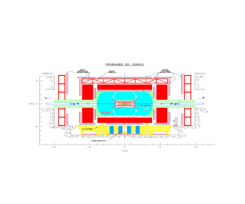
The DØ detector as implemented for Run II of the Tevatron Collider has been described elsewhere [2]. A side view of the DØ experiment for Run II is shown in Fig. 1. In this section we concentrate on the limitations of the various subsystems for operation at the TeV33 Collider. These limitations fall into two categories: the deterioration of the detectors as a result of the increased integral radiation dose (aging); and the limitation on detector and system operation as a result of the increased instantaneous luminosity and the concomitant increase in rates. In addition, we consider the effects of the environment on our ability to extract the crucial physics.
2.1 Calorimeter
The DØ calorimeter consists of three cryostats, each containing calorimeter modules of depleted uranium, steel, and copper, immersed in liquid argon. The electronics systems have been modified for Run II to accommodate bunch crossing spacings of 132 ns. Although the technology is fundamentally radiation hard, the high instantaneous luminosity projected for TeV33 substantially increases the average energy deposited during the calorimeter’s ns integration time. This increase leads to two principal areas of concern: the technical limitations on the calorimeter performance at high luminosity due to the calorimeter design, and the effect of the increased energy from underlying events on physics analyses.
2.1.1 Technical Limitations
As the luminosity is increased, the performance of the DØ calorimeter will be affected by the increase in energy absorbed per unit time. While the DØ calorimeter is thought to be immune to radiation damage, the increase in particle flux leads to an increase in the ionization current flowing across the liquid-argon gap, thereby dropping the gap voltage by a few percent at worst. This effect is discussed in Appendix A.
At present, the calorimeter readout is expected to utilize three abort gaps in the train of accelerator bunches. If the number of gaps were reduced in order to increase the total number of bunches, the resultant small increase in noise in the calorimeter would be acceptable (discussed below).
2.1.2 Physics Effects
The average energy deposited in a calorimeter tower ( in space) by minimum bias events was measured during Run I using zero-bias triggers without noise suppression (i.e., pedestal subtraction). Scaling to a luminosity of cm-2s-1, with 108 bunches and the upgraded shaping electronics, minimum bias events will contribute an average transverse energy of MeV for central EM towers and MeV for central hadronic towers. For comparison, in Run I the central underlying-event energy was dominated by uranium noise, which gave an average energy (not ) deposit of MeV in a central EM tower and MeV in a central hadronic tower. Thus, the underlying event at TeV33 is expected to be dominated by the minimum bias events accompanying the hard process.
The effect of underlying-event noise is expected to have minor impact on most of the DØ TeV33 physics program. The jet energy resolution will continue to be dominated by fragmentation and showering fluctuations. The precision of the measurement of the top quark mass is expected to be set by systematic errors in the jet energy scale and the Monte Carlo modeling of gluon radiation. A study of large missing SUSY signatures [4] found that the rejection of QCD background events was not significantly affected by underlying-event pileup.
The measurement that might be most affected by underlying-event noise is the precision measurement of the -boson mass. The effect of increased pile-up was studied for the TeV2000 report [14], with the conclusion that a mass uncertainty of 30 MeV/c2 was achievable with 10 fb-1, using the currently favored transverse-mass technique. The resolution in transverse mass at high luminosity is dominated by the resolution in missing , with the contribution from underlying-event noise becoming roughly equal to the intrinsic detector resolution at a luminosity of cm-2s-1 [15]. Further increases in luminosity are likely to degrade the transverse-mass resolution. Nevertheless, one would expect TeV33 to yield a factor of improvement in the statistical error over our present Run I results. The challenge is to achieve a comparable reduction in systematic error. Alternative techniques of measuring the mass are also conceivable. For example, the transverse momentum distribution of the lepton is less sensitive than is the transverse mass to degradation in missing transverse energy resolution. One particular approach [16] that has been tried is the ratio method, where and events are analyzed in an identical manner by ignoring one of the electrons in decay. This method has been applied to the DØ Run Ia sample, yielding a statistical error of 360 MeV/c2 for 13 pb-1. The statistical error on the ratio method extrapolates to MeV/c2 for TeV33, with a potentially smaller systematic error than can be achieved from fits to the transverse mass. This is due to the reduced sensitivity to the modeling of production, and the cancellation of effects from the underlying event [17]. Note that this should be particularly true for the muon decay channel.
2.1.3 Summary
The present DØ calorimeter appears to be capable of operating in the TeV33 environment. The increase in noise from underlying events is mostly a concern for the precision measurement of the mass. This measurement is expected to be limited by our understanding of systematic uncertainties.
2.2 Preshower Detectors
The DØ preshower detectors consist of a central unit [18] and two forward modules [19]. They are designed to improve electron identification in Run II. The detectors [20] are composed of radiators and extruded triangular scintillating strips with embedded wavelength-shifting (WLS) fiber readout. Scintillation light produced by charged particles in the radiators is collected by the WLS fibers and piped through clear fibers to visible light photon counters (VLPC) outside the calorimeter. The central detector covers the pseudorapidity range , and the forward detectors cover the range . An online electron trigger is realized by requiring a large pulse in the preshower detectors to be matched with either a track in the fiber tracker for the central detector, or in the strips of scintillator in front of the converters in the forward detectors.
In Appendix B, we discuss the potential problems from high occupancy, rate and radiation damage in operating the preshower detectors at TeV33. Occupancy will be approximately 10% for an instantaneous luminosity of . Recent studies show that such rates do not have significant impact on the VLPC performance. The main effect is from radiation damage to the scintillator in high regions. At , an integrated luminosity of 30 fb-1 results in a dose of about 500 krad.
We conclude that the central and part () of the forward preshower detectors can operate well for a TeV33 luminosity of . The region of high pseudorapidity () is expected to suffer significant but gradual radiation damage. However, since most high- electrons are in the central region (), the high- physics program is not expected to be affected by this problem.
2.3 Muon Detectors
The layout of the DØ muon system for Run II is shown in Fig. 1. It consists of a central and two forward iron toroids and associated detectors. In the central region (1.0), two layers of scintillation trigger counters are used to trigger on muons and reduce cosmic ray backgrounds. Proportional drift tubes (PDT) are used to reconstruct muon tracks. They have drift cells with a cross section of 5 cm 10 cm and lengths of up to 6 m.
In the forward region (), there are three layers of scintillation counters with projective tower geometry. Their segmentation is 4.5∘ in by 0.1 in . For muon track reconstruction, there are three layers of mini drift tubes (MDT), with a total of ten detector planes. They have drift cells of 1 cm 1 cm cross section, and are up to 6 m in length. To reduce backgrounds from beam jets and interactions with accelerator elements, special shielding (see Fig. 1) is installed around the beam pipe. It consists of soft steel, polyethylene, and lead, and it reduces background fluxes in the forward muon detectors by up to a factor 50 relative to the rates without shielding. To accommodate the reduction in beam-crossing time from 3.5 s to 132 ns, all of the muon electronics are being rebuilt using a deadtimeless pipeline.
At a hadron collider, full geometric coverage for 2 provides 90% acceptance for the decay products of massive objects. The muon-detector acceptance for 2 is around 80%. The losses are mainly due to the presence of “no detector” zones under the calorimeter (supports) and between some chambers.
A discussion of the operation of the muon system at higher luminosities can be found in Ref.[21]. Hits expected from muons are negligible in comparison to those from other sources. The most serious of these backgrounds is from remnants of high energy showers leaking through the detector. In addition, low energy neutrons create a “neutron gas” inside the collision hall. The only serious problem is the 15% occupancy in the central PDT system for a luminosity of .
Based on experience in running the detectors in 1994–96, the central muon PDTs can handle approximately 1 mC/cm of anode charge which corresponds to about 1 fb-1 of integrated luminosity with the upgraded detector and improved shielding. The aging is primarily due to deposition on the signal wires. Although methods of cleaning anode wires have been developed, implementation requires a long shutdown period. The useful lifetime between cleanings is much less than the 30 fb-1 exposure planned for TeV33, and this will consequently pose logistical difficulty.
In summary, all the muon detectors, except the central PDTs, will be able to run at a luminosity of , and for an integrated luminosity of 30 fb-1.
2.4 Tracking Detectors
The DØ Tracker consists of a silicon-strip vertex tracker and a central scintillating-fiber tracker. The tracking devices are situated close to the beam (2.5 cm 52 cm) and surround the collision region, as shown in Fig. 2. The silicon detector provides identification and reconstruction of primary event vertices and secondary decay vertices. The fiber detector also provides a Level 1 track trigger with programmable thresholds.

As the luminosity of the Tevatron collider rises above cm-2s-1, the increase in the mean number of collisions per crossing () leads to a rapid degradation of the Level 1 track triggering capability. Also, extended periods of high luminosity operation will pose a problem for detector performance for the inner layers of both detectors.
2.4.1 Silicon Microstrip Tracker
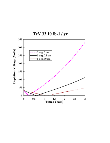
Silicon devices suffer significant damage from large radiation doses [22]. Eventually this leads to a change in material properties. As a result of these changes, the voltage required for full depletion first decreases, and then increases as the material passes through type inversion, as shown in Fig. 3. As a result of the elevated depletion voltage, it is expected that the inner layers of the detectors will be inoperable after an integrated luminosity of the order of 5–10 fb-1.
2.4.2 Scintillating Fiber Tracker
The impact of high luminosity on the scintillating-fiber detector is discussed in Appendix C. Higher luminosity operation at TeV33 will slightly modify the detected photoelectron distribution, fiber efficiency, and fiber-doublet ribbon efficiency. The primary problem is that occupancy will increase beyond 10% for an instantaneous luminosity greater than . At this point, both the trigger performance and the pattern recognition capabilities will be put at risk.
2.4.3 Summary
The inner layers of both the silicon detector and the fiber detector have problems with the increased luminosity of TeV33. In the case of the former, radiation damage will render the detectors inoperable. In the latter, as a result of the increased occupancy, the effectiveness of the detector will be much reduced.
2.5 Triggers
On average, there are eighteen interactions per crossing at and 108 bunches. Calorimeter-based triggers are not very sensitive to the number of minimum bias events in a crossing, but tracking triggers are sensitive because of the increased probability for false tracks. Trigger rejection for the fiber tracker decreases roughly quadratically with the number of minimum bias events so a factor of 10 increase in luminosity worsens the rejection by a factor of 100. In addition, the number of minimum bias events per crossing is Poisson distributed and, for example, when = 18, one percent of the crossings will have 28 or more interactions. Tracking triggers will unfortunately tend to select crossings with large numbers of minimum bias events rather than events of interest.
We assume that TeV33 physics interests will center on processes with high . We expect a high trigger rate of 3–4 kHz in Run II. In a TeV33 scenario in which we employ luminosity leveling and use the maximum number of bunches, the event rate per crossing increases by a factor of up to four, so the real trigger rate increases approximately by this amount. (A 4 kHz trigger rate is small compared to the 7 MHz crossing rate). This gives a Level 1 trigger rate of 12–16 kHz. Although this does not greatly exceed our Run II design goal of 10 kHz, the estimate contains no contingency. A factor of two would offer a reasonable safety factor, which would imply the need for a peak rate of about 20 kHz.
2.5.1 Calorimeter Trigger
The present calorimeter Level 1 trigger forms towers that are 0.20.2 in – space. Each tower is summed in depth to give an electromagnetic and a hadronic signal. These signals are available to the trigger framework. In addition, signals from (–) trigger towers are summed to form “large tile” signals which are used to search for jets. There are four electromagnetic threshold reference sets, four jet threshold reference sets, and eight large-tile reference sets. Each set has different energy thresholds for each tower. Several global quantities are summed for the entire calorimeter and also compared to sets of reference values. These quantities include the vector sum of transverse momenta (used for missing- triggers) and scalar sums of EM- and of Jet-. For Run II, there is provision for direct readout to the DAQ system, and a scan of the history of the previous 25 crossings.
For instantaneous luminosities in excess of , the rejection offered by this system becomes inadequate.
2.5.2 Muon Trigger
The estimated muon trigger rate at Level 1 for a luminosity of , using the Run II trigger hardware is 10 kHz (see Appendix D). The uncertainty on this number is large, reflecting uncertainties in our modeling accuracy and the limited Monte Carlo statistics presently available. However, with the expected TeV33 scenario of an instantaneous luminosity of , this rate is approximately 4 kHz, or less with moderate tightening of muon requirements.
2.5.3 Tracking Trigger
The Level 1 tracking trigger for Run II is formed by a logical AND of hits from the 8 axial layers of the scintillating fiber tracker. Monte Carlo studies show that the probability of finding a false track is a steep function of the number of tracks in the detector. This is demonstrated in Fig. 4 where we display the increase in wrong associations between different views in the fiber tracker. The dependence on luminosity at different radii clearly shows that the most critical effects are at the inner radii.
3 The DØ Detector: Possible Upgrades
3.1 Calorimeter
We have seen that eliminating two of the three Tevatron abort gaps could allow an increase in the number of bunches from 108 to 146, with a consequent 26% reduction in energy deposition in the calorimeter from underlying events. Running with two less abort gaps will require some modification to the calorimeter readout since there are insufficient capacitors in the switched capacitor arrays (SCAs) to hold all 146 samples. This modification may result in small pedestal shifts that will have to be corrected when the readout “wraps” around from the last capacitor in the SCA to the first. In addition, there will be a slight increase in electronic noise due to longer times between baseline sampling. The benefits being independent of the particular bunch structure have led us to incorporate the appropriate modifications for Run II.
3.2 Preshower Detectors
A possible upgrade to the central preshower system is to replace the three layers of scintillating strips with one layer of scintillating pads, which would provide the tracker with the capability of triggering in both the – and – views. A pad size of 2 cm 8 cm yields the same number of channels as the current design. The pad design effectively reduces the occupancy by a factor of four, and requires no additional photodetectors or electronics.
3.3 Muon Detectors
High occupancies and fast aging require the replacement of the central proportional drift-tube system for TeV33. We propose to replace these chambers with chambers similar to the MDTs. The MDTs can be produced in any preselected length, in large quantities, and relatively inexpensively. They can be made to be the same sizes as current PDT chambers, and will simply fit into the existing detector. A total of 72,000 channels is needed to replace the central system. (In the forward muon system, 48,000 MDT cells will be used for Run II.) The rest of the muon system can be used unchanged.
3.4 Tracking Detectors
An efficient central tracking system and a robust Level 1 trigger are important for successful operation of DØ under TeV33 conditions. Pattern recognition and tracking are great challenges at high luminosities. We base our considerations on the tracking system for Run II. However, as discussed above, there are major problems for the inner layers of the silicon microstrip tracker being developed for Run II at the Tevatron, and for the inner layers of the scintillating-fiber tracker. Here we consider several recovery options.
Since radiation exposure falls off nearly [23] as the square of the radial distance from the beam, it is clear that withdrawing the inner silicon layers from 2.5 cm to a position at 4 or 5 cm will lead to a factor of 2.5 to 4 increase in useful detector lifetime. However, this can significantly degrade the impact-parameter resolution of the detector.
We can consider:
-
•
An R&D effort to develop a suitable replacement detector:
-
1.
Radiation hard silicon microstrip detectors. There are efforts under the auspices of the LHC R&D program to develop such detectors with improved immunity to radiation [24].
-
2.
Development of appropriate silicon pixel detectors. Because of their smaller element size, these devices are intrinsically more radiation hard [25].
-
3.
Development of an alternative strip technology, such as diamond [26].
-
1.
-
•
Relocation of the silicon microstrip tracker to a larger radial region (4 cm 16 cm).
- •
-
•
Modification of the fiber tracker:
-
1.
Relocation of the scintillating-fiber tracking layers to larger radii (35 cm 52 cm). This has been studied, especially in connection with the trigger [29].
-
2.
Splitting the fibers in the middle (at = 0) for the layers at small radii. This increases the number of channels, and therefore also the space required to accommodate the clear connecting fibers and VLPC cryostats.
-
3.
Reduction of the fiber diameter from 830 m to 500 m. R&D on smaller diameter VLPCs would be required, and it may be that the increased number of channels would lead to space problems in extracting the signals. Some work might also be required on optimizing 500 m fibers, although the projection from the performance of 830 m is promising.
-
1.
Detailed simulation of tracking and triggering and an active ongoing program of detector R&D are required to make a rational choice among these options, which are not necessarily exclusive. For the scintillating fibers this program includes studies and optimization of smaller-diameter scintillating fibers (500 m), and smaller diameter VLPC pixels ( arrays in the same silicon area as the current arrays). For microstrip detectors, evaluation of diamond microstrip detectors, development of radiation-hard silicon strip detectors, and development of local trigger towers based on these technologies are needed. For pixels, R&D on adapting the LHC [25] pixel detectors and readout for DØ is required. (A Fermilab development effort [30] has already been established in this last area).
3.5 Triggers
It is necessary to address the increased Level 1 acceptance rate. We could move some of the rejection power in the Level 2 processors to Level 1, so that we can fit all the high physics into the existing 10 kHz bandwidth.
3.5.1 Calorimeter Trigger
Improving calorimeter-trigger rejection requires a new Level 1 trigger system for the calorimeter. This system would move the isolation criteria for EM jets to Level 1. It would improve the hadron part of Level 1 by allowing a more flexible combination of towers than is provided by the large tiles. That is, one could have a moving window that would search for isolated jets rather than large fixed tiles. This would also provide the of the trigger so that there could be a match between the tracker, preshower and calorimeter. Putting the isolation cut at Level 1 should increase rejection by a factor of two to three for electrons. It is not yet known if the changes to the hadron trigger would give the additional rejection that is required.
3.5.2 Tracking Triggers
Three options have been considered.
-
•
An option [27] which involves a complete rework of the tracking to incorporate an extensive pixel system in a new technology, possibly microgap chambers.
-
•
An option which goes hand in hand with a reconfiguration of fiber tracking layers to larger radii [29] could provide more axial layers in the trigger than the Run II design.
-
•
A novel system [31] based on using a silicon pixel detector in the trigger at Level 1.
The first option is revolutionary and requires very extensive modification of the tracking. The second option is less powerful and indeed would likely not be adequate for a luminosity of . However it might be adequate in the TeV33 luminosity-leveled scenario with an effective . The third option depends on the pixel development.
4 Conclusions
Based on the discussion of the previous section we advance a preliminary suite of upgrades, which would be sufficient to ensure good operation of the detector at luminosities up to and including a maximum instantaneous intensity of with a bunch separation of 132 ns.
-
•
Calorimeter
No change.
-
•
Preshower Detectors
No change.
-
•
Muon Detectors
Replace the central PDT system with the chambers similar to those that will be used in the forward muon system in Run II.
-
•
Tracking Detectors
-
1.
At small radii (less than 10 cm) introduce pixel detectors as replacements for the inner layers of the silicon detector.
-
2.
Between 10 cm and 30 cm in radius, augment the present silicon layers with new detectors, perhaps utilizing the space of the present inner scintillating-fiber layers.
-
3.
For radii greater than 30 cm, reconfigure the existing fiber tracker channels to maximize effectiveness in momentum determination and triggering.
-
1.
-
•
Triggers
-
1.
Base the Level 1 tracking trigger on the redeployment of the scintillating fiber tracker at larger radii, perhaps with a pixel trigger.
-
2.
Upgrade the Level 1 calorimeter system to use dynamic large-tile triggering, along with isolation for electromagnetic triggers.
-
1.
The physics that can be done with 30 fb-1 of data at the Tevatron is highly compelling. The DØ detector will perform well in the TeV33 environment with these or similar upgrades.
References
- [1] DØ Collaboration, http://www-d0.fnal.gov/public/d0 physics v2.html.
-
[2]
DØ Collaboration, http://www-d0.fnal.gov/hardware/upgrade/upgrade.html. “The DØ Upgrade:
The Detector and Its Physics”, Fermilab Pub-96/357-E,
http://higgs.physics.lsa.umich.edu/dzero/d0pac96/d0doc.html. - [3] DØ Collaboration, http://www-d0.fnal.gov/newd0/d0atwork/computing.html.
- [4] “Future Electroweak Physics at the Fermilab Tevatron: Report of the TeV2000 Study Group,” D. Amidei and R. Brock, editors, Fermilab-Pub-96/082.
- [5] R. Frey et al., “Top Quark Physics: Future Measurements”, New Directions for High-Energy Physics, p 760., Proceedings of the 1996 DPF/DPB Summer Study on High-Energy Physics, Snowmass, Colorado, Ed. D.G. Cassel, L. Trindle Gennari and R. H. Siemann, Stanford Linear Accelerator Center, 1997.
- [6] U. Baur et al., “Weakly Coupled Higgs Boson and Precision Electroweak Physics”, New Directions for High-Energy Physics, p 499., Proceedings of the 1996 DPF/DPB Summer Study on High-Energy Physics, Snowmass, Colorado, Ed. D.G. Cassel, L. Trindle Gennari and R. H. Siemann, Stanford Linear Accelerator Center, 1997.
- [7] S. Mrenna et al., “Report of the Supersymmetry Theory Subgroup”, New Directions for High-Energy Physics, p 760., Proceedings of the 1996 DPF/DPB Summer Study on High-Energy Physics, Snowmass, Colorado, Ed. D.G. Cassel, L. Trindle Gennari and R. H. Siemann, Stanford Linear Accelerator Center, 1997.
- [8] S. Kim et al., “Improvement of Signal Significance in Search at TeV33”, New Directions for High-Energy Physics, p 610., Proceedings of the 1996 DPF/DPB Summer Study on High-Energy Physics, Snowmass, Colorado, Ed. D.G. Cassel, L. Trindle Gennari and R. H. Siemann, Stanford Linear Accelerator Center, 1997.
- [9] W.-M. Yao, “Prospects for Observing Higgs in Channel at TeV33”, New Directions for High-Energy Physics, p 619., Proceedings of the 1996 DPF/DPB Summer Study on High-Energy Physics, Snowmass, Colorado, Ed. D.G. Cassel, L. Trindle Gennari and R. H. Siemann, Stanford Linear Accelerator Center, 1997.
- [10] D. Hedin, “Study of the Mass Resolution of Dijets”, New Directions for High-Energy Physics, p 608., Proceedings of the 1996 DPF/DPB Summer Study on High-Energy Physics, Snowmass, Colorado, Ed. D.G. Cassel, L. Trindle Gennari and R. H. Siemann, Stanford Linear Accelerator Center, 1997.
- [11] J. Marriner, “The Fermilab Proton-Antiproton Collider Upgrades”, New Directions for High-Energy Physics, p 78., Proceedings of the 1996 DPF/DPB Summer Study on High-Energy Physics, Snowmass, Colorado, Ed. D.G. Cassel, L. Trindle Gennari and R. H. Siemann, Stanford Linear Accelerator Center, 1997.
- [12] P. Bagley et al., “Summary of the TeV33 Accelerator Working Group”, New Directions for High-Energy Physics, p 134., Proceedings of the 1996 DPF/DPB Summer Study on High-Energy Physics, Snowmass, Colorado, Ed. D.G. Cassel, L. Trindle Gennari and R. H. Siemann, Stanford Linear Accelerator Center, 1997.
- [13] F. Borcherding et al., “Report of the TeV33 Detector Working Group”, New Directions for High-Energy Physics, p 405., Proceedings of the 1996 DPF/DPB Summer Study on High-Energy Physics, Snowmass, Colorado, Ed. D.G. Cassel, L. Trindle Gennari and R. H. Siemann, Stanford Linear Accelerator Center, 1997.
- [14] “Future Electroweak Physics at the Fermilab Tevatron: Report of the TeV2000 Study Group,” D. Amidei and R. Brock, editors, Fermilab-Pub-96/082, pp 65-73.
- [15] P. Nemethy and A. Mincer, “Pileup Effects on Mass Measurement,” DØ Note 1398, April 1992; and “Original Electronics versus Upgrade Electronics: Comparison of Pileup at Full Luminosity,” DØ Note 1642, April 1993.
- [16] S. Rajagopalan and M. Rijssenbeek, “Measurement of using the Transverse Mass Ratio of and ”, New Directions for High-Energy Physics, p 537., Proceedings of the 1996 DPF/DPB Summer Study on High-Energy Physics, Snowmass, Colorado, Ed. D.G. Cassel, L. Trindle Gennari and R. H. Siemann, Stanford Linear Accelerator Center, 1997.
- [17] A. Kotwal, “Effects of Multiple Interactions and Pileup on the Mass Measurement in the Electron Channel in DØ in Run II and TeV33”, New Directions for High-Energy Physics, p 530., Proceedings of the 1996 DPF/DPB Summer Study on High-Energy Physics, Snowmass, Colorado, Ed. D.G. Cassel, L. Trindle Gennari and R. H. Siemann, Stanford Linear Accelerator Center, 1997. Fermilab-Conf-97/011-E.
- [18] M. Adams et al., “Design Report of the Central Preshower Detector for the DØ Upgrade,” DØNote 3014, January 1996.
- [19] DØ Collaboration, “The DØ Upgrade: Forward Preshower, Muon System and Level 2 Trigger,” DØ Note 2894, March 1996.
-
[20]
M. Adams et al., Nucl. Instrum. Methods A366,
263 (1995);
M. Adams et al., Nucl. Instrum. Methods A378, 131 (1996). - [21] D. Denisov, “DØ Muon System at TeV33”, New Directions for High-Energy Physics, p 412., Proceedings of the 1996 DPF/DPB Summer Study on High-Energy Physics, Snowmass, Colorado, Ed. D.G. Cassel, L. Trindle Gennari and R. H. Siemann, Stanford Linear Accelerator Center, 1997.
- [22] A.P. Heinson and J. Ellison, “Effects of Radiation Damage on the DØ Silicon Tracker”, DØ Note 2679, July 1995.
- [23] D. Amidei et al., “Status of Radiation Damage to the SVX”, CDF/SVX/DOC/PUBLIC/2061, April 1993.
- [24] CERN-RD48, “Further Work on Radiation Hardening of Silicon Detectors”, Rose Collaboration, http://www.brunel.ac.uk/research/rose/.
- [25] CERN-RD19, “ Development of Hybrid and Monolithic Silicon Micropattern Detectors”, S. Albergo et al., CERN/LHCC 97-59, LEB Status Report/RD19, October 1997.
- [26] CERN-RD42, “Development of Diamond Tracking Detectors for High Luminosity Experiments at the LHC”, http://www.cern.ch/RD42/
- [27] G. Watts and M. Johnson, “Using Microgap Chambers as a Self-contained Trigger in DØ for TeV33”, New Directions for High-Energy Physics, p 426., Proceedings of the 1996 DPF/DPB Summer Study on High-Energy Physics, Snowmass, Colorado, Ed. D.G. Cassel, L. Trindle Gennari and R. H. Siemann, Stanford Linear Accelerator Center, 1997.
- [28] CDF Collaboration, “CDF II Technical Design Report”, November 1996, FERMILAB-Pub-96/390-E, p 6-1.
- [29] R. Partridge and G. Watts, “Upgrading the DØ Fiber Tracker for TeV33”,New Directions for High-Energy Physics, p 420., Proceedings of the 1996 DPF/DPB Summer Study on High-Energy Physics, Snowmass, Colorado, Ed. D.G. Cassel, L. Trindle Gennari and R. H. Siemann, Stanford Linear Accelerator Center, 1997.
- [30] J. Appel and S. Kwan, private communication; S. Kwan, Status Report, Fermilab Pixel R&D, January 1998.
- [31] S. Mani and M. Narain, “Inner Tracker and L1 Trigger Based on Pixel Detectors for DØ33”, DØ Note 3409, January 1998.
- [32] S. Margulies and M. Chung, “Estimation of Radiation Doses in the DØ Upgrade Scintillating-Fiber Tracker and Central Preshower Counter,” DØ Note 2394, November 1994.
Appendices
Appendix A Rate Effects on the Calorimeter High Voltage
We consider the effects of increased energy deposition rate on the DØ calorimeter operation. In particular we consider the effect of increased current draw on the effective high voltage and the consequent effect on the observed signal. We find the effect to be finite and manageable.
The high voltage supply is connected to the resistive coat on the signal electrode planes. The ionization current was calculated as a function of pseudorapidity for the four electromagnetic(EM) layers by converting the average energy deposit to the average charge measured by the calorimeter electronics and taking into account the unmeasured image charge associated with the slow-moving positive ions. The ionization current was assumed to be evenly distributed among the liquid argon gaps in ganged subsection and the voltage drop across the resistive coat was calculated. Since the drift velocity of the ionized electrons in the argon depends on the electric field, a large voltage drop across the resistive coat will change the shape of the signal pulse and decrease the charge collection efficiency. The largest voltage drop occurs for the EM2 layer in the end calorimeter(EC) at largest , located near the shower maximum for low photons from minimum bias events.
The voltage drop has been calculated from the average energy per beam crossing deposited in the calorimeter. The data used were taken from zero bias runs with calorimeter noise suppression turned off. The ionization current is given by
| (1) |
where is the average energy deposited in a beam crossing, is the sampling fraction, is the electron charge, is the beam crossing frequency, and is the ionization potential for argon.
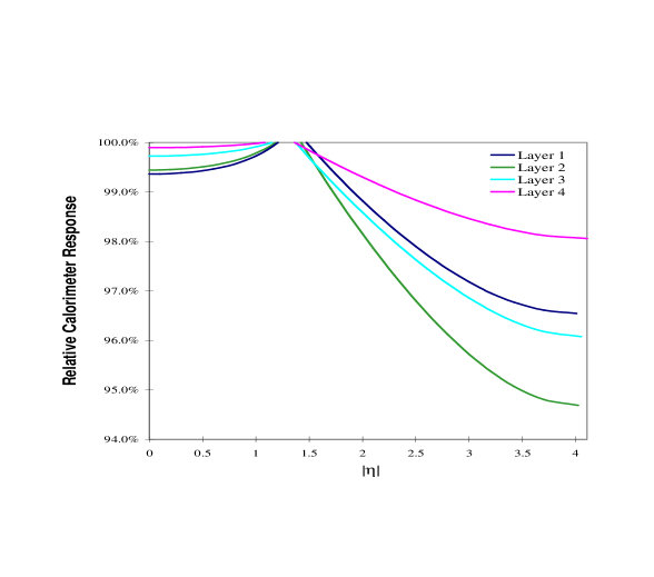
The changing drift velocity will affect the calorimeter energy response and likely require luminosity- and pseudorapidity-dependent corrections. If this voltage drop is converted to a change in response, the effect is quite small, due to the rather gentle dependence of the response on high voltage in the plateau region. This is shown in Fig. 5 where we have assumed an instantaneous luminosity of and the current 2.0 kV operating value.
Appendix B Radiation Damage, Occupancy, and Rate Effects in the Preshower Detectors
B.1 Radiation Damage
Albedo neutrons from the calorimeter, and charged and neutral hadrons from interactions are the main sources of radiation in the preshower detectors [32].
The central tracking volume is filled with albedo neutrons which are uniformly distributed in , the distance perpendicular to the beams. The logarithmic energy spectrum peaks roughly around 1 MeV. The estimated neutron flux density at a luminosity of . Using a conversion factor of 1 neutron/cm rad, the dose rate from neutrons is given by rad/s.
Assuming a minimum bias cross section of 50 mb, and 4 charged particles per unit of pseudorapidity, the charged particle flux at a radius is . Taking into account a factor of two for low loopers, the dose rate from the charged particles is given by rad/s, where is the specific ionization.
Most neutral hadrons from beam interactions are ’s, with an average of 0.5 GeV/c. From isospin symmetry, the flux is expected to be half the flux of charged particles. Assuming each photon from decay cascades to 4 electrons in the solenoid and the lead, the expected dose rate from neutral hadrons is rad/s.
Adding the rates from neutron, charged and neutral hadrons together, the total dose rate at is rad/s. The total radiation doses for the central and forward preshower detectors are shown in Fig. 6 as functions of integrated luminosity. The detailed calculation can be found in Ref. [32]. The above calculation has been checked using fully simulated minimum bias events for the central detector. The numbers from the calculation and the simulation agree very well. The expected radiation level for an integrated luminosity of 30 fb-1 in Run III is 54 krad for the central preshower, 140 krad at and about 400 krad at for the forward preshower. The dose in the central detector is well below the level at which the scintillator or fibers are affected. However, the dose in the forward detectors is high. The scintillator and fibers in the region will suffer gradual but substantial radiation damage and therefore the performance of the forward preshower detectors will degrade significantly over the last part of TeV33.

![[Uncaptioned image]](/html/hep-ex/9804011/assets/x7.png) Figure 7: The expected occupancy as a function of the energy
deposition in the axial strips of the central preshower detector for minimum
bias events (MBE) and for events with one and four minimum bias
events overlayed.
Figure 7: The expected occupancy as a function of the energy
deposition in the axial strips of the central preshower detector for minimum
bias events (MBE) and for events with one and four minimum bias
events overlayed.
B.2 Occupancy
At a luminosity of with a 132 ns bunch spacing, on average there will be about 7-8 interactions per crossing. Figure 7 shows the expected occupancies as functions of the energy deposition for the axial strips of the Run II central preshower detector for minimum bias events and events with four minimum bias events overlayed. Here the occupancy is defined as the ratio of the number of strips with hit with energies above threshold, and the total number of strips. The occupancies for the stereo strips are expected to be slightly worse. The occupancies at 1 MIP threshold are about 2% for one minimum bias event and about 17% for a typical event overlayed with four minimum bias events, where the unit MIP is defined as the most probable energy deposited in the layer by a muon. Assuming the occupancy increases linearly with the number of minimum bias events, about 23% of the strips will be hit for a event at a luminosity cm-2 s-1. Even with a 3 MIP threshold, the occupancy will be around 9%. This high occupancy level will probably affect the online electron trigger more than offline electron identification.
B.3 The Rate (Non)Issue
The high rate expected for the high luminosity is a concern for the visible light photon counters(VLPC). The issue of the gain and quantum efficiency (QE) of the VLPC at high rate has been studied in detail. The single photoelectron (PE) rate is approximately given by y, where is the instantaneous luminosity, is the total cross section, is the occupancy with a 1 MIP threshold and is the photoelectron yield for a 1 MIP energy deposition. The factor of two is included to take into account the yield from hits below threshold. Although failing the threshold, these hits still contribute to the single PE rate. For the Run II design luminosity of cm-2s-1, the single PE rate is about 8 MHz assuming mb, = 2% and PE/MIP 111This is the expected photoelectron yield based on the cosmic–ray test, see [20] for details. for axial strips of the central detector. At a Run III luminosity of cm-2s-1, the single PE rate is 40 MHz, five times higher. However, it should be noted that a yield of 20 PE/MIP has a considerable safety margin for achieving the required performance of the preshower detector. Halving the yield is not expected to significantly degrade the performance of the detector. Nominally, a 20 MHz rate capability of the VLPCs is needed. Including a factor of two for the uncertainty, we conclude that a 40 MHz VLPC rate capability will be sufficient for the Run III application. Recent studies (see Appendix C) of the VLPC characteristics seem to indicate that the gain and QE of the new VLPCs show little dependence on the rate implying that rate is not a problem.
Appendix C Radiation Damage, Rate Effects, and Occupancy in the Fiber Tracker
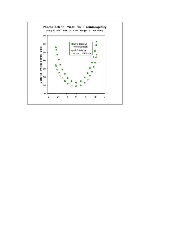
Figure 8 shows the mean detected photoelectron(PE) signal for a scintillating fiber on the inner barrel of the CFT. The multiclad fiber (830 m diameter and 1.7 m length) is optically coupled to a clear fiber waveguide of identical diameter and 10 m length, and is read out with a VLPC. The minimum detected PE signal occurs for minimum ionizing particles traversing the fiber at normal incidence near the mid-point along the fiber length, which corresponds to the minimum path length. At this location (), we expect to detect a mean of 11 PE/MIP. A threshold in photoelectron equivalents is set for every channel of the CFT, which establishes the noise rate and efficiency for each. Typically, thresholds are set at 1–1.5 PE, yielding noise rates 0.5%, and efficiencies99%. The efficiency of a fiber-doublet ribbon also exceeds 99% under these conditions.
C.1 Radiation Damage to the Scintillating Fibers
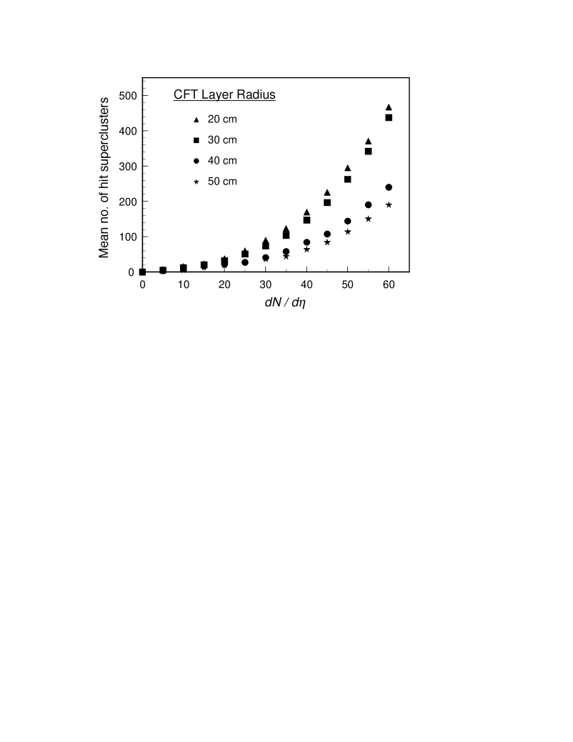
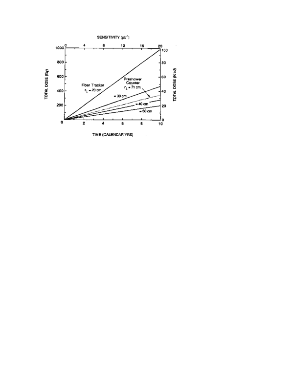
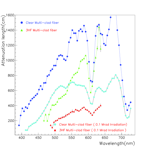
The effect of radiation damage [32] is approximately proportional to . Hence, detectors placed at the inner radii are most at risk, see Fig. 9. In one TeV33 year, we expect an integrated dose of approximately 100 krad to scintillating fibers situated on the innermost support cylinder ( = 20 cm) of the CFT. This corresponds to a factor of two reduction in the optical attenuation length of these fibers, see Fig. 10. Additionally, 1.5 m of the clear fiber waveguide will be similarly affected. Together, these effects result in a 33% drop in the detected photoelectron yield at 0 from fibers placed at cm, as indicated in Fig. 8.
The light loss reduces the tracking efficiency for an inner fiber-doublet layer from a value 99% to 98%. While designed to survive for 10 years of operation in Run II, the inner scintillating fiber layers would need to be moved to larger radii for Run III.

C.2 Rate Dependence of the VLPCs
Potential rate dependences of the gain and quantum efficiency of the visible light photon counters have been studied for 1600 channels of the devices to be used in Run II. By operating them at a temperature of 9K and at a nominal 6.5 V bias, full performance can be maintained at photorates well above those expected for either Run II or Run III. Figure 11 displays the efficiency of these devices at 40 MHz. The rate dependence leads to a reduction in detection efficiency per fiber doublet ribbon from 99% to 98% up to the maximum luminosity expected.
C.3 Increased Occupancy of the Fiber Layers.
Tracking detector occupancy is proportional to , see Fig. 12. Simulation studies have shown (Fig. 4) that ghost clusters in the tracking layers and Level 1 tracking-trigger rates increase as a strong function (more than linear) of . This occurs because the dominant contribution to tracking triggers at fixed threshold are fakes (accidental alignments of combinations of hits from lower tracks) particularly in jets. To operate within the 10 kHz trigger bandwidth available into Level 2, it is essential to maintain a useful Level 1 track trigger in combination with calorimeter, preshower, and muon-system triggers. This necessitates keeping as small as possible and also keeping the occupancy per fiber as small as possible. Luminosity leveling can control . Minimizing the occupancy per fiber requires either modification or repositioning of the fiber layers at larger radii.

Appendix D Muon Trigger Rates
The Level 1 muon trigger for TeV33 is planned to be the same as that used in Run II. The Run II Level 1 muon trigger searches for muons locally in octants in each central and forward geographic region. Within each octant, one muon trigger card uses combinatoric logic to match tracks from the CFT track trigger with either central or forward muon scintillation counters. The 20 ns gate used with the scintillation counters provides a powerful means of rejecting particles associated with showers originating in beam line elements or detector edges. A second muon trigger card searches for muons using wire hit information from the central PDTs and forward MDTs. Wire hits are confirmed by coincidence with the corresponding scintillation counters. Because the MDTs have three or four decks in each layer, track “stubs” or centroids can be formed. The angle of these “stubs” provides additional rejection of background not associated with the primary collisions. The octant trigger decisions for each region are collected by a muon trigger crate manager which forms trigger decision bits for that region. A “loose” muon trigger is defined as the coincidence of a CFT track above a given threshold with muon scintillator hits found in the 20 ns gate. A “tight” muon trigger requires additionally, centroids found using muon chamber hit information. Regional trigger decisions from the muon trigger crate managers are sent to the muon trigger manager which forms a global muon trigger decision which is sent to the trigger framework for inclusion in the global physics trigger.
Muon trigger rates for TeV33 have been estimated using isajet two-jet event samples generated with 1, 2, 4, and 6 interactions per crossing. The events were fully simulated in the Run II detector using geant. A simulation of the muon trigger logic was used to find the pass rate as a function of the number of interactions per crossing. An extrapolation of the pass rate was made to estimate the rate for the of events with interactions per crossing. There is an uncertainty on the estimated trigger rate of approximately a factor of two due to uncertainties in how well the isajet/geant simulation reflects actual TeV33 conditions and to limited Monte Carlo statistics.
A goal of the design of the Run II muon system upgrade is to have two basic triggers which are unprescaled: a high single muon trigger and a low dimuon trigger. The former is the “” trigger which is also used for top physics and new phenomena searches. The latter is a “” physics trigger which also collects a large sample of ’s for calibration. The background rate for the “loose” version of these triggers is shown in Fig. 13 as a function of luminosity. To set the scale for the rate due to actual physics processes, the single muon rate from production alone is roughly 100 Hz at the TeV33 luminosity. For Run II, the rate for both triggers is Hz but the effect of multiple interactions is clearly visible in Fig. 13 from the nonlinear rise in rates with luminosity. These early studies indicate that the “loose” triggers may be problematic for TeV33. The additional rejection, however, available from the “tight” trigger should be sufficient to control the rates for TeV33. In particular, the “tight” single muon trigger has a rate well below 100 Hz at a luminosity of compared with 4 kHz for the “loose” single muon trigger. The conclusion is that the muon trigger rates will, with minimal efficiency loss, stay within their allotted Level 1 bandwidth for TeV33.